EP0163807B1 - Home video system with teletext decoder - Google Patents
Home video system with teletext decoder Download PDFInfo
- Publication number
- EP0163807B1 EP0163807B1 EP85100987A EP85100987A EP0163807B1 EP 0163807 B1 EP0163807 B1 EP 0163807B1 EP 85100987 A EP85100987 A EP 85100987A EP 85100987 A EP85100987 A EP 85100987A EP 0163807 B1 EP0163807 B1 EP 0163807B1
- Authority
- EP
- European Patent Office
- Prior art keywords
- teletext
- signal
- recording
- supplied
- switch
- Prior art date
- Legal status (The legal status is an assumption and is not a legal conclusion. Google has not performed a legal analysis and makes no representation as to the accuracy of the status listed.)
- Expired
Links
Images

Classifications
-
- H—ELECTRICITY
- H04—ELECTRIC COMMUNICATION TECHNIQUE
- H04N—PICTORIAL COMMUNICATION, e.g. TELEVISION
- H04N21/00—Selective content distribution, e.g. interactive television or video on demand [VOD]
- H04N21/40—Client devices specifically adapted for the reception of or interaction with content, e.g. set-top-box [STB]; Operations thereof
- H04N21/47—End-user applications
- H04N21/488—Data services, e.g. news ticker
- H04N21/4888—Data services, e.g. news ticker for displaying teletext characters
-
- H—ELECTRICITY
- H04—ELECTRIC COMMUNICATION TECHNIQUE
- H04N—PICTORIAL COMMUNICATION, e.g. TELEVISION
- H04N21/00—Selective content distribution, e.g. interactive television or video on demand [VOD]
- H04N21/40—Client devices specifically adapted for the reception of or interaction with content, e.g. set-top-box [STB]; Operations thereof
- H04N21/47—End-user applications
-
- H—ELECTRICITY
- H04—ELECTRIC COMMUNICATION TECHNIQUE
- H04N—PICTORIAL COMMUNICATION, e.g. TELEVISION
- H04N5/00—Details of television systems
- H04N5/76—Television signal recording
- H04N5/765—Interface circuits between an apparatus for recording and another apparatus
- H04N5/775—Interface circuits between an apparatus for recording and another apparatus between a recording apparatus and a television receiver
-
- H—ELECTRICITY
- H04—ELECTRIC COMMUNICATION TECHNIQUE
- H04N—PICTORIAL COMMUNICATION, e.g. TELEVISION
- H04N5/00—Details of television systems
- H04N5/76—Television signal recording
- H04N5/91—Television signal processing therefor
- H04N5/92—Transformation of the television signal for recording, e.g. modulation, frequency changing; Inverse transformation for playback
- H04N5/9201—Transformation of the television signal for recording, e.g. modulation, frequency changing; Inverse transformation for playback involving the multiplexing of an additional signal and the video signal
- H04N5/9206—Transformation of the television signal for recording, e.g. modulation, frequency changing; Inverse transformation for playback involving the multiplexing of an additional signal and the video signal the additional signal being a character code signal
- H04N5/9207—Transformation of the television signal for recording, e.g. modulation, frequency changing; Inverse transformation for playback involving the multiplexing of an additional signal and the video signal the additional signal being a character code signal for teletext
Landscapes
- Engineering & Computer Science (AREA)
- Multimedia (AREA)
- Signal Processing (AREA)
- Television Signal Processing For Recording (AREA)
- Television Systems (AREA)
Abstract
Description
Die vorliegende Erfindung betrifft eine Videoheimanlage mit einem Fernsehempfänger, einen an die AV-Buchse des Fernsehempfängers anschließbaren Videorecorder und einen mit dem Fernsehempfänger verbundenen Videotextdecoder, dem vom Fernsehempfänger das FBAS-Signal, das die codierten Videotext- Signale enthält, und mindestens eine Versorgungsspannung zugeführt werden.The present invention relates to a video home system with a television receiver, a video recorder that can be connected to the AV socket of the television receiver and a teletext decoder connected to the television receiver, to which the composite signal containing the coded teletext signals and at least one supply voltage are supplied by the television receiver .
Ein Videotextdecoder der im Oberbegriff des Anspruchs 1 genannten Art ist beispielsweise aus der Zeitschrift "GRUNDIG Technische Informationen", 4/5-1980, Seite 171 - 196, bekannt. Da der Aufbau und die Funktionsweise des bekannten Videotextdecoders für die vorliegende Erfindung von Bedeutung sind, wird dieser zunächst mit Hilfe der Fig. 1 näher erläutert.A teletext decoder of the type mentioned in the preamble of claim 1 is known, for example, from the magazine "GRUNDIG Technical Information", 4 / 5-1980, pages 171-196. Since the structure and mode of operation of the known teletext decoder are important for the present invention, this is first explained in more detail with the aid of FIG. 1.
Der in Figur 1 dargestellte Videotextdecoder besteht im wesentlichen aus einem Videoprozessor 1, einer Datenverarbeitungsschaltung 2, einem Seitenspeicher 3, einem Zeichengenerator 4, einer Taktsteuerung 5, einem Videotext-Fernsteuer-Interface 6 und einem Spannungsstabilisator 7.The teletext decoder shown in FIG. 1 essentially consists of a video processor 1, a
Zur Versorgung benötigt der bekannte Videotextdecoder zwei Spannungen (12 V für den Videoprozessor und 5 V für die weiteren Schaltkreise), die aus Spannungen E und M' abgeleitet werden, die im Fernsehempfänger vorhanden sind, und das FBAS-Signal, das die codierten Videotextsignale enthält und üblicherweise am ZF-Verstärker des Fernsehempfängers abgenommen wird. Diese Signale liegen an den Eingängen a und b bzw. c des Videotextdecoders an.For the supply, the known teletext decoder requires two voltages (12 V for the video processor and 5 V for the further circuits) which are derived from voltages E and M 'which are present in the television receiver and the CVBS signal which contains the coded teletext signals and is usually removed from the IF amplifier of the television receiver. These signals are present at inputs a and b and c of the teletext decoder.
Ferner erhält der Videotextdecoder über seinen Eingang d Signale von einem nicht gezeichneten Fernsteuerempfänger zugeführt, die charakteristisch für die eingegebenen Bedienbefehle sind. Diese Signale werden im Videotext-Fernsteuer-Interface 6 für die weiteren Schaltungen des Videotextdecoders aufbereitet.Furthermore, the teletext decoder receives via its input d signals from a remote control receiver, not shown, which are characteristic of the entered operating commands. These signals are processed in the teletext
Das dem Eingang c zugeführte FBAS-Signal gelangt an einen Videoprozessor 1, in dem die digitalen Textsignale abgetrennt und zur Datenverarbeitungsschaltung 2 weitergegeben werden.The CVBS signal fed to the input c reaches a video processor 1 in which the digital text signals are separated and passed on to the
Die Datenverarbeitungsschaltung 2 unterzieht die seriell ankommenden Daten einer Paritäts-und Hammingcode-Prüfung, wandelt sie in parallele Datenwörter um und leitet diese parallelen Datenwörter an den Seitenspeicher 3 weiter.The
Die im Seitenspeicher 3 gespeicherten Datenworte werden schließlich einem Zeichengenerator 4 zugeführt, der die Aufgabe hat, die ihm zugeführten Datenwörter als Schrift-oder Grafikzeichen auf dem Bildschirm des Fernsehempfängers darzustellen.The data words stored in the
Zur Steuerung des gesamten Zeitablaufes ist eine Schaltung 5 zur Taktsteuerung vorgesehen, die über die Leitung M mit dem FBAS-Signal synchronisiert wird und unter anderem an den Videoprozessor 1 ein vollständiges und normgerechtes Synchronsignal liefert.To control the entire time sequence, a
Die dem Videotextdecoder über seine Eingänge a und b zugeführten Spannungen werden in einem Spannungsstabilisator 7 stabilisiert. Mit den an den Ausgängen des Spannungsstabilisators 7 erhaltenen Spannungen, die beispielsweise + 5 V und + 12 V betragen, werden die einzelnen Schaltungsteile des Videotextdecoders versorgt.The voltages supplied to the teletext decoder via its inputs a and b are stabilized in a
Über die Ausgänge e, f, und g des Videotextdecoders (RGB-Ausgänge) gelangen die aus dem Speicher des Zeichengenerators ausgelesenen Zeichen zum RGB-Baustein des angeschlossenen Farbfernsehempfängers, dem über den Ausgang h des Videotextdecoders weiterhin ein Blanking- oder Bildaustastsignal zur Austastung des hinter dem darzustellenden Videotext gelegenen Bilderszenenabschnittes zugeführt wird. Ferner kann am Zeichengenerator 4 ein Videotext-Luminanzsignal abgenommen werden, welches am Ausgang i zur Verfügung steht. Über den Ausgang j des Videotextdecoders erfolgt die Synchronisierung des Fernsehempfängers. Bei Videotextbetrieb gibt der Videoprozessor 1 an den Ausgang j des Videotextdecoders das von der Taktsteuerung 5 erzeugte und dem Videoprozessor 1 über die Leitung L zugeführte normgerechte Synchronsignal ab.Via the outputs e, f, and g of the teletext decoder (RGB outputs), the characters read from the memory of the character generator reach the RGB module of the connected color television receiver, which continues to have a blanking or blanking signal for blanking the behind via the output h of the teletext decoder the video scene section to be displayed is supplied. Furthermore, a teletext luminance signal can be taken from the
Weitere Einzelheiten über den bekannten Videotextdecoder können der eingangs genannten Literaturstelle entnommen werden.Further details on the known teletext decoder can be found in the literature mentioned at the beginning.
Ferner ist in der älteren europäischen Patentanmeldung EP-A-123 959 ein Videorecorder mit Aufzeichnung eines Videotext-Signals beschrieben. Bei diesem Videorecorder wird das empfangene Videotext-Signal unmittelbar anstelle des Bildträgers aufgezeichnet.Furthermore, in the older European patent application EP-A-123 959 a video recorder with a recording of a teletext signal is described. With this video recorder, the received teletext signal is recorded immediately instead of the image carrier.
Der vorliegenden Erfindung liegt die Aufgabe zugrunde, eine Videoheimanlage mit Fernsehempfänger, einem Videorecorder und einem Videotextdecoder der im Oberbegriff des Anspruchs 1 angegebenen Art so weiterzubilden, daß auf möglichst einfache und billige Art und Weise und ohne Eingriffe in den Fernsehempfänger selbst eine Aufzeichnung der Videotextsignale, insbesondere synchron mit den Fernsehsignalen, auf einem Heimvideorecorder möglich wird, dessen Aufzeichnungsbandbreite für die Aufzeichnung der Original-Videotextinformation nicht ausreichend und dessen Wiedergabesignal mit einem Zeitfehler behaftet ist.The present invention has for its object to develop a video home system with a television receiver, a video recorder and a teletext decoder of the type specified in the preamble of claim 1 in such a way that recording of the teletext signals themselves is as simple and cheap as possible and without interfering with the television receiver, in particular in synchronism with the television signals, is possible on a home video recorder, the recording bandwidth of which is not sufficient for the recording of the original teletext information and the playback signal of which has a time error.
Diese Aufgabe wird durch die im Kennzeichen des Patentanspruchs 1 angegebenen Maßnahmen gelöst. Vorteilhafte Weiterbildungen ergeben sich aus den Unteransprüchen.This object is achieved by the measures specified in the characterizing part of patent claim 1. Advantageous further developments result from the subclaims.
Die Vorteile der Erfindung liegen insbesondere darin, daß die vorliegende Schaltung nur mit dem Videotextdecoder verbunden werden muß und sonst keine Lötverbindungen zum TV-Chassis notwendig sind. Dies schafft eine einfache und preiswerte Möglichkeit, Videotextsignale synchron mit dem Fernsehsignal auf einem Heimvideorecorder aufzuzeichnen, obwohl dessen Aufzeichnungsbandbreite für die Aufzeichnung der Original-Videotextinformation nicht ausreichend und dessen Wiedergabesignal mit einem Zeitfehler behaftet ist.The advantages of the invention lie in particular in the fact that the present circuit only has to be connected to the teletext decoder and otherwise no solder connections to the TV chassis are necessary. This provides a simple and inexpensive way to record teletext signals in synchronism with the television signal on a home video recorder, although its recording bandwidth is not sufficient for the recording of the original teletext information and its playback signal is subject to a time error.
Mit Hilfe der vorliegenden Erfindung können beispielsweise Gehörgeschädigte Videotext-Untertitel auf Magnetband aufzeichnen.With the aid of the present invention, for example, hearing-impaired videotext subtitles can be recorded on magnetic tape.
Weitere Vorteil und Eigenschaften ergeben sich aus einem Ausführungsbeispiel, das im folgenden mit Hilfe der Figur 2 näher erläutert wird.Further advantages and properties result from an exemplary embodiment which is explained in more detail below with the aid of FIG. 2.
Der obere Teil von Figur 2 enthält den bereits in Figur 1 beschriebenen bekannten Videotextdecoder, bestehend aus einem Videoprozessor 1, einer Datenverarbeitungsschaltung 2, einem Seitenspeicher 3, einem Zeichengenerator 4, einer Taktsteuerung 5, einem Videotext-Fernsteuer-Interface 6 und einem Spannungsstabilisator 7.The upper part of FIG. 2 contains the known teletext decoder already described in FIG. 1, consisting of a video processor 1, a
An diesen bekannten Videotextdecoder wird in der in Figur 2 gezeigten Weise der Videotext- Aufzeichnungsadapter angeschlossen. Die Eingänge dieses Videotext-Aufzeichnungsadapters sind mit k, m, n, o, p, q, und r, und die Ausgänge mit s und t bezeichnet, wobei der Ausgang t in einer bestimmten Betriebsart auch als Eingang verwendet wird, wie später noch erläutert wird.The teletext recording adapter is connected to this known teletext decoder in the manner shown in FIG. The inputs of this teletext recording adapter are labeled k, m, n, o, p, q, and r, and the outputs are labeled s and t, the output t also being used as an input in a specific operating mode, as will be explained later becomes.
Die Eingänge k und n des Videotext-Aufzeichnungsadapters dienen als Versorgungseingänge. Ihnen werden die im Spannungsstabilisator 7 des Videotextdecoders erzeugten Spannungen von 5 V und 12 V zugeführt.The inputs k and n of the teletext recording adapter serve as supply inputs. The voltages of 5 V and 12 V generated in the
Am Eingang m des Videotext-Aufzeichnungsadapters liegt das im Zeichengenerator 4 des Videotextdecoders erzeugte und am Ausgang i des Videotextdecoders abgreifbare Videotext-Luminanzsignal an.The teletext luminance signal generated in the
Der Eingang o des Videotext-Aufzeichnungsadapters ist mit dem Ausgang h des Videotextdecoders verbunden, so daß dem Videotext-Aufzeichnungsadapter über seinen Eingang o das vom Zeichengenerator 4 ausgegebene Blanking- oder Bildaustastsignal zugeführt wird, welches im Videotextaufzeichnungsadapter als Umschaltsignal für die Eintastung des decodierten Videotextsignals in das am Eingang q des Videotext-Aufzeichnungsadapters anliegende FBAS-Signal verwendet wird.The input o of the teletext recording adapter is connected to the output h of the teletext decoder, so that the blanking or blanking signal output by the
Weiterhin weist der Videotext- Aufzeichnungsadapter einen Eingang p auf, an dem das in der Taktsteuerung 5 erzeugte, über die Leitung L an den Videoprozessor weitergegebene und am Ausgang j des Videotextdecoders abgreifbare Synchrongemisch anliegt. Dieses Synchrongemisch wird bei Vollbildtext-Aufzeichnung verwendet, d. h., wenn das gesamte Bild ausgetastet und nur Text auf dem Recorder aufgezeichnet werden soll.Furthermore, the teletext recording adapter has an input p at which the synchronous mixture generated in the
Schließlich benötigt der Videotext- Aufzeichnungsadapter noch die im Heimvideorecorder erzeugte Schalt-Spannung, die bei der Betriebsart "Aufzeichnung" 0 V und bei der Betriebsart "Wiedergabe" 12 V beträgt, und an Pin 1 der AV-Buchse 12 des AV-Kupplungsteils K abgenommen werden kann und allgemein als AV-Schaltspannung bezeichnet wird. AV steht dabei für Audio-Video, weil über die AV-Buchse das Audio-und Videosignal ein-und ausgekoppelt wird.Finally, the teletext recording adapter still needs the switching voltage generated in the home video recorder, which is 0 V in the "recording" operating mode and 12 V in the "playback" operating mode, and is removed at pin 1 of the
Ferner hat der Videotext- Aufzeichnungsadapter einen Ausgang s für die Bildschirmwiedergabe und einen Ausgang t für die Aufzeichnung des Signals auf dem angeschlossenen Heimvideorecorder, wobei der Ausgang t bei der Wiedergabe als Eingang für das vom Heimvideorecorder kommende Signel verwendet wird.Furthermore, the teletext recording adapter has an output s for screen display and an output t for recording the signal on the connected home video recorder, output t being used during playback as an input for the signal coming from the home video recorder.
Bei normalem FBAS-Signal befindet sich der Pegel des Umschaltsignals, das dem Videotext- Aufzeichnungsadapter über seinen Anschluß o zugeführt wird, auf "LOW". Dies bewirkt ein Sperren des Transistors T2 und ein Leiten des Transistors T3. Als Folge davon wird der Schalter S2 geschlossen und der Schalter S1 geöffnet. Diese Schalter dienen der schnellen Signalumschaltung (FBAS-Videotext) innerhalb des Fernsehrasters. Also kann das am Eingang q anliegende FBAS-Signal über die geschlossenen Schalter S2 und S3 (S3 ist im Aufzeichnungsbetrieb ständig geschlossen) über den Ausgang t des Videotext-Aufzeichnungsadapters an den Heimvideorecorder weitergegeben werden. Der Schalter S4 ist bei Aufzeichnungsbetrieb geöffnet, bei Wiedergabebetrieb geschlossen.In the case of a normal CVBS signal, the level of the switching signal which is fed to the teletext recording adapter via its connection o is at "LOW". This causes transistor T2 to be blocked and transistor T3 to conduct. As a result, switch S2 is closed and switch S1 is opened. These switches are used for fast signal switching (composite video teletext) within the television grid. The CVBS signal present at input q can thus be passed on to the home video recorder via the closed switches S2 and S3 (S3 is always closed in recording mode) via the output t of the teletext recording adapter. The switch S4 is open in the recording mode and closed in the playback mode.
Beim Vorliegen eines Videotextsignals befindet sich der Pegel des am Anschluß o anliegenden Umschalt-Signals auf "HIGH". Dies bewirkt ein Leiten des Transistors T2 und ein Sperren des Transistors T3. Als Folge davon wird der Schalter S1 geschlossen und der Schalter S2 geöffnet. Also kann das am Eingang m anliegende decodierte Textsignal über die geschlossenen Schalter S1 und S3 über den Ausgang t des Videotext-Aufzeichnungsadapters an das Aufzeichnungsgerät weitergegeben werden.If a teletext signal is present, the level of the changeover signal present at connection o is "HIGH". This causes transistor T2 to conduct and transistor T3 to turn off. As a result, switch S1 is closed and switch S2 is opened. The decoded text signal present at input m can thus be passed on to the recording device via the closed switches S1 and S3 via the output t of the teletext recording adapter.
Insgesamt gesehen findet also eine Eintastung des decodierten Videotextsignals in das am Eingang q des Videotext-Aufzeichnungsadapters anliegende FBAS-Signal statt, so daß das decodierte Videotextsignal synchron mit dem FBAS-Signal auf dem Heimvidoerecorder aufgezeichnet wird.Seen overall, the decoded teletext signal is therefore keyed into the CVBS signal present at the input q of the teletext recording adapter, so that the decoded teletext signal is recorded in synchronism with the CVBS signal on the home video recorder.
Beim Wiedergabevorgang liegt am Eingang r eine AV-Schaltspannung von 12 V an. Dies bewirkt ein Leiten des Transistors T6 und ein Schließen des Schalters S4. Bei leitendem Transistor T6 liegt der Steuereingang des Schalters S3 über die Kollektor-Emitter-Strecke des Transistors T6 an Masse, so daß der Schalter S3 geöffnet ist. Also kann beim Wiedergabevorgang das vom Heimvideorecorder kommende, am Eingang t des Videotext-Aufzeichnungsadapters anliegende Signal über den Schalter S4 und den Ausgang s an den Farbdecoder des Fernsehempfängers weitergegeben und über die RGB-Endstufe auf dem Bildschirm dargestellt werden.During the playback process there is an AV switching voltage of 12 V at input r. This causes the transistor T6 to conduct and the switch S4 to close. When transistor T6 is conductive, the control input of switch S3 is connected to ground via the collector-emitter path of transistor T6, so that the switch S3 is open. Thus, during the playback process, the signal coming from the home video recorder and present at the input t of the teletext recording adapter can be passed on to the color decoder of the television receiver via the switch S4 and the output s and displayed on the screen via the RGB output stage.
Bei Vollbildtext-Aufzeichnung, d. h., wenn das gesamte Bild ausgetastet und nur Videotext aufgezeichnet werden soll, hat das dem Eingang o des Videotext-Aufzeichnungsadapters zugeführte Bildaustast- bzw. Umschaltsignal den Pegel "HIGH", so daß der Transistor T2 ständig leitet. Das am Eingang p des Videotext-Aufzeichnungsadapters anliegende Synchrongemisch kann dann über die Transistoren T4, T2 und T3 dem Schalter S1 zugeführt werden.With full screen text recording, i.e. that is, if the entire picture is to be blanked and only teletext is to be recorded, the picture blanking or switching signal fed to the input o of the teletext recording adapter has the level "HIGH", so that the transistor T2 is always on. The synchronous mixture present at the input p of the teletext recording adapter can then be supplied to the switch S1 via the transistors T4, T2 and T3.
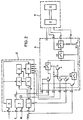
Die Figur 3 zeigt ein Beispiel dafür, wie das in Figur 2 gezeigte AV-Kupplungsteil K, über das die Ausgangssignale des Videotext-Aufzeichnungsadapters A dem Videorecorder 15 zugeführt werden, in der Videoleitung 17 zwischen der AV-Buchse 13 des Fernsehempfängers 14 und der AV-Buchse 16 des Videorecorders 15 angeordnet sein kann. Mit 11 ist der AV-Stecker des AV-Kupplungsteils K bezeichnet, der in die AV-Buchse 13 des Fernsehempfängers eingesteckt wird. Der Videorecorder 15 ist über die Videoleitung 17 an die AV-Buchse 12 des AV-Kupplungsteils K angeschlossen.FIG. 3 shows an example of how the AV coupling part K shown in FIG. 2, via which the output signals of the teletext recording adapter A are fed to the
Eine vorteilhafte Weiterbildung der Erfindung besteht darin, den Videotext- Aufzeichnungsadapter und das AV-Kupplungsteil zu einer baulichen Einheit zu verbinden, die als Zusatzbauteil nur an den Videotextdecoder des Fernsehempfängers angeschlossen werden braucht.An advantageous development of the invention consists in connecting the teletext recording adapter and the AV coupling part to form a structural unit which, as an additional component, only needs to be connected to the teletext decoder of the television receiver.
Eine weitere vorteilhafte Weiterbildung besteht darin, daß die Schalter S1 und S2 zu einem einzigen Schalter zusammengefaßt sind.Another advantageous development is that the switches S1 and S2 are combined into a single switch.
Claims (7)
Priority Applications (1)
| Application Number | Priority Date | Filing Date | Title |
|---|---|---|---|
| AT85100987T ATE41280T1 (en) | 1984-05-10 | 1985-01-31 | HOME VIDEO SYSTEM WITH A TELETEXT DECODER. |
Applications Claiming Priority (2)
| Application Number | Priority Date | Filing Date | Title |
|---|---|---|---|
| DE3417276 | 1984-05-10 | ||
| DE19843417276 DE3417276A1 (en) | 1984-05-10 | 1984-05-10 | VIDEO HOME SYSTEM WITH A VIDEO TEXT DECODER |
Publications (2)
| Publication Number | Publication Date |
|---|---|
| EP0163807A1 EP0163807A1 (en) | 1985-12-11 |
| EP0163807B1 true EP0163807B1 (en) | 1989-03-08 |
Family
ID=6235436
Family Applications (1)
| Application Number | Title | Priority Date | Filing Date |
|---|---|---|---|
| EP85100987A Expired EP0163807B1 (en) | 1984-05-10 | 1985-01-31 | Home video system with teletext decoder |
Country Status (3)
| Country | Link |
|---|---|
| EP (1) | EP0163807B1 (en) |
| AT (1) | ATE41280T1 (en) |
| DE (1) | DE3417276A1 (en) |
Cited By (1)
| Publication number | Priority date | Publication date | Assignee | Title |
|---|---|---|---|---|
| DE3928175A1 (en) * | 1989-01-21 | 1990-07-26 | Nokia Unterhaltungselektronik | VIDEO RECEIVER |
Families Citing this family (3)
| Publication number | Priority date | Publication date | Assignee | Title |
|---|---|---|---|---|
| DE3733563A1 (en) * | 1987-10-03 | 1989-04-20 | Grundig Emv | DEVICE FOR PLAYING A VIDEO SIGNAL RECORDED ON A MAGNETIC TAPE OF A VIDEO RECORDER |
| DE3920234A1 (en) * | 1989-06-21 | 1991-01-03 | Thomson Brandt Gmbh | VIDEO RECORDER WITH GENERATING A TEXT SIGNAL |
| FR2670982A1 (en) * | 1990-12-21 | 1992-06-26 | Thomson Consumer Electronics | METHOD FOR SYNCHRONIZING CONTROL FUNCTIONS WITH VIDEO SIGNALS IN A TELEVISION RECEIVER AND DEVICE FOR IMPLEMENTING SAME. |
Family Cites Families (2)
| Publication number | Priority date | Publication date | Assignee | Title |
|---|---|---|---|---|
| DE3315687C1 (en) * | 1983-04-29 | 1984-11-22 | Telefunken Fernseh Und Rundfunk Gmbh, 3000 Hannover | Circuit for recording a television video signal and a teletext signal by means of a video recorder |
| DE3315740C2 (en) * | 1983-04-30 | 1985-02-21 | Telefunken Fernseh Und Rundfunk Gmbh, 3000 Hannover | Video recorder with recording of a teletext signal |
-
1984
- 1984-05-10 DE DE19843417276 patent/DE3417276A1/en active Granted
-
1985
- 1985-01-31 EP EP85100987A patent/EP0163807B1/en not_active Expired
- 1985-01-31 AT AT85100987T patent/ATE41280T1/en active
Cited By (1)
| Publication number | Priority date | Publication date | Assignee | Title |
|---|---|---|---|---|
| DE3928175A1 (en) * | 1989-01-21 | 1990-07-26 | Nokia Unterhaltungselektronik | VIDEO RECEIVER |
Also Published As
| Publication number | Publication date |
|---|---|
| DE3417276C2 (en) | 1987-02-19 |
| EP0163807A1 (en) | 1985-12-11 |
| DE3417276A1 (en) | 1985-11-14 |
| ATE41280T1 (en) | 1989-03-15 |
Similar Documents
| Publication | Publication Date | Title |
|---|---|---|
| US4568981A (en) | Font recall system and method of operation | |
| DE3923907C2 (en) | ||
| DE69734159T2 (en) | TELEVISION WITH INTEGRATED RECEIVER DECODER | |
| CN1100581A (en) | On-screen display generator | |
| DE19752507A1 (en) | Device for generating a digital video image | |
| EP0163807B1 (en) | Home video system with teletext decoder | |
| EP0387517B1 (en) | Device to process television reception signals for recognition and selection of picture format | |
| EP0421017B1 (en) | Circuit arrangement for picture-in-picture insertion in a television set with only one tuner | |
| DE3632484C2 (en) | ||
| US5786863A (en) | High resolution recording and transmission technique for computer video and other non-television formatted video signals | |
| EP0695491B1 (en) | Method for compatible recording or playback of television signals | |
| EP0746165B1 (en) | Apparatus comprising a tunable receiver circuit for receiving analogue and/or digital television signals | |
| DE69936957T2 (en) | A video signal processor for processing a video signal by means of a plurality of data-driven processors and television receivers equipped therewith | |
| DE3823284A1 (en) | DEVICE FOR PROCESSING VIDEO SIGNALS | |
| DE3642186A1 (en) | VIDEO RECORDER WITH A SECOND VIDEO SIGNAL WAY | |
| EP0129648B1 (en) | Television receiver with text insertion | |
| DE69822883T2 (en) | DEVICE FOR GENERATING DIGITAL DATA FOR IMAGES IN AN ANIMATION / INFORMATION SEQUENCE FOR AN ELECTRICAL DEVICE | |
| DE19621778A1 (en) | Image processing system with input output source selection e.g. for VCR | |
| DE19815808B4 (en) | video recorder | |
| EP0310880A1 (en) | Arrangement for reproducing a video signal recorded on a magnetic tape of a video tape recorder | |
| EP0695086B1 (en) | Method for transmitting a television signal, an accompanying signal and a control signal for displaying as a large or small image | |
| EP0367929A2 (en) | Device for reducing flicker in television receivers | |
| EP0368220B1 (en) | Device for copying a video signal from a first video apparatus to a second one | |
| EP0429789B1 (en) | Device for the processing of two videosignals | |
| DE4103539A1 (en) | Television monitor with picture-in-picture processing - has N-connections for N-different video picture sources and contains N-picture-in-picture processing circuits |
Legal Events
| Date | Code | Title | Description |
|---|---|---|---|
| PUAI | Public reference made under article 153(3) epc to a published international application that has entered the european phase |
Free format text: ORIGINAL CODE: 0009012 |
|
| AK | Designated contracting states |
Designated state(s): AT FR GB IT |
|
| 17P | Request for examination filed |
Effective date: 19860524 |
|
| 17Q | First examination report despatched |
Effective date: 19880128 |
|
| GRAA | (expected) grant |
Free format text: ORIGINAL CODE: 0009210 |
|
| AK | Designated contracting states |
Kind code of ref document: B1 Designated state(s): AT FR GB IT |
|
| REF | Corresponds to: |
Ref document number: 41280 Country of ref document: AT Date of ref document: 19890315 Kind code of ref document: T |
|
| GBT | Gb: translation of ep patent filed (gb section 77(6)(a)/1977) | ||
| ET | Fr: translation filed | ||
| ITF | It: translation for a ep patent filed |
Owner name: STUDIO JAUMANN |
|
| PLBE | No opposition filed within time limit |
Free format text: ORIGINAL CODE: 0009261 |
|
| STAA | Information on the status of an ep patent application or granted ep patent |
Free format text: STATUS: NO OPPOSITION FILED WITHIN TIME LIMIT |
|
| 26N | No opposition filed | ||
| ITTA | It: last paid annual fee | ||
| PGFP | Annual fee paid to national office [announced via postgrant information from national office to epo] |
Ref country code: AT Payment date: 19921230 Year of fee payment: 9 |
|
| PG25 | Lapsed in a contracting state [announced via postgrant information from national office to epo] |
Ref country code: AT Effective date: 19940131 |
|
| REG | Reference to a national code |
Ref country code: GB Ref legal event code: 746 Effective date: 19940208 |
|
| ITPR | It: changes in ownership of a european patent |
Owner name: OFFERTA DI LICENZA AL PUBBLICO |
|
| REG | Reference to a national code |
Ref country code: FR Ref legal event code: DL |
|
| PGFP | Annual fee paid to national office [announced via postgrant information from national office to epo] |
Ref country code: GB Payment date: 19950123 Year of fee payment: 11 |
|
| PGFP | Annual fee paid to national office [announced via postgrant information from national office to epo] |
Ref country code: FR Payment date: 19951227 Year of fee payment: 12 |
|
| PG25 | Lapsed in a contracting state [announced via postgrant information from national office to epo] |
Ref country code: GB Effective date: 19960131 |
|
| REG | Reference to a national code |
Ref country code: FR Ref legal event code: CD |
|
| GBPC | Gb: european patent ceased through non-payment of renewal fee |
Effective date: 19960131 |
|
| PG25 | Lapsed in a contracting state [announced via postgrant information from national office to epo] |
Ref country code: FR Effective date: 19960930 |
|
| REG | Reference to a national code |
Ref country code: FR Ref legal event code: ST |