EP0163770A1 - Electrostatic copying apparatus - Google Patents
Electrostatic copying apparatus Download PDFInfo
- Publication number
- EP0163770A1 EP0163770A1 EP84115737A EP84115737A EP0163770A1 EP 0163770 A1 EP0163770 A1 EP 0163770A1 EP 84115737 A EP84115737 A EP 84115737A EP 84115737 A EP84115737 A EP 84115737A EP 0163770 A1 EP0163770 A1 EP 0163770A1
- Authority
- EP
- European Patent Office
- Prior art keywords
- supporting frame
- copying
- photosensitive member
- lens
- image
- Prior art date
- Legal status (The legal status is an assumption and is not a legal conclusion. Google has not performed a legal analysis and makes no representation as to the accuracy of the status listed.)
- Granted
Links
Images


Classifications
-
- G—PHYSICS
- G03—PHOTOGRAPHY; CINEMATOGRAPHY; ANALOGOUS TECHNIQUES USING WAVES OTHER THAN OPTICAL WAVES; ELECTROGRAPHY; HOLOGRAPHY
- G03G—ELECTROGRAPHY; ELECTROPHOTOGRAPHY; MAGNETOGRAPHY
- G03G15/00—Apparatus for electrographic processes using a charge pattern
- G03G15/04—Apparatus for electrographic processes using a charge pattern for exposing, i.e. imagewise exposure by optically projecting the original image on a photoconductive recording material
- G03G15/041—Apparatus for electrographic processes using a charge pattern for exposing, i.e. imagewise exposure by optically projecting the original image on a photoconductive recording material with variable magnification
- G03G15/0415—Apparatus for electrographic processes using a charge pattern for exposing, i.e. imagewise exposure by optically projecting the original image on a photoconductive recording material with variable magnification and means for controlling illumination or exposure
-
- G—PHYSICS
- G03—PHOTOGRAPHY; CINEMATOGRAPHY; ANALOGOUS TECHNIQUES USING WAVES OTHER THAN OPTICAL WAVES; ELECTROGRAPHY; HOLOGRAPHY
- G03G—ELECTROGRAPHY; ELECTROPHOTOGRAPHY; MAGNETOGRAPHY
- G03G15/00—Apparatus for electrographic processes using a charge pattern
- G03G15/04—Apparatus for electrographic processes using a charge pattern for exposing, i.e. imagewise exposure by optically projecting the original image on a photoconductive recording material
- G03G15/041—Apparatus for electrographic processes using a charge pattern for exposing, i.e. imagewise exposure by optically projecting the original image on a photoconductive recording material with variable magnification
Definitions
- This invention relates to an electrostatic copying apparatus, and particularly to an electrostatic copying apparatus capable of giving copies at variable ratios including enlargement and reduction.
- the present invention has been accomplished in view of the above fact, and its object is to overcome or eliminate the various inconveniences and defects of conventional electrostatic copying apparatuses capable of giving copies at variable ratios, and to improve them in various respects.
- the illustrated copying apparatus has a substantially parallelpipedal housing shown generally at 2. On the upper surface of the housing 2 is disposed a transparent plate 4 on which to place an original document to be copied.
- the transparent plate 4 is supported by a supporting frame (not shown) mounted on the upper surface of the housing 2 for free movement in the left and right directions in Figure 1.
- the transparent plate 4 is caused to make a preparatory movement toward the right in Figure 1 from its stop position shown by solid lines in Figure 1 to its start-of-scan position shown by a two-dot chain line 4A in Figure 1; then to make a scanning movement toward the left in Figure 1 from.
- An openable and closable document holding member (not shown) for convering the transparent plate 4 and the document thereon is also mounted on the supporting frame (not shown) on which the transparent plate 4 is supported.
- a horizontal base plate 6 is disposed to divide the inside of the housing 2 into an upper space and a lower space.
- a cylindrical rotating drum 8 constituting a supporting base for a photosensitive member
- a photosensitive member 10 is disposed on at least a part of the peripheral surface of the rotating drum 8.
- the rotating drum 8 there may be used an endless belt-like element known to those skilled in the art, and the photosensitive member 10 may be disposed on at least a part of the surface of the endless belt-like element.
- a charging corona discharging device 14 Around the rotating drum rotated in the direction of an arrow 12 are disposed successively in its rotating direction a charging corona discharging device 14, a charge-eliminating lamp 16 to be operated during reduced scale copying, a developing device 18, a transfer corona discharging device 20 and a cleaning device 22.
- the charging corona discharging device 14 charges the photosensitive member 10 to a specified polarity substantially uniformly.
- An exposure zone 24 exists between the charging corona discharging device 14 and the charge-eliminating lamp 16. In the exposure zone 24, the image of the original document on the transparent plate 4 is projected by an optical device to be described hereinbelow, thereby forming a latent electrostatic cimage on the photosensitive member 10. As will be described hereinbelow,.
- the charge-eliminating lamp 16 is operated when reduced scale copying is performed.
- the lamp 16 illuminates one side portion of the photosensitive member 10 which has been charged by the corona discharger 14 but on which the image of the original document has not been projected in the exposure zone 24. Thus, the electric charge on this one side portion is removed.
- the developing device 18 which may be of any known form applies toner particles to the latent electrostatic image on the photosensitive member 10 to develop it into a toner image.
- the transfer corona discharging device 20 applies a corona discharge to the back of a copying paper to be contacted with the surface of the photosensitive member 10 in a transfer zone 26, thereby transferring the toner image on the photosensitive member 10 to the copying paper.
- the illustrated cleaning device 22 is selectively held at its operating position shown by a solid line in Figure 1 or its non-operating position shown by a two-dot chain line.
- a blade 28 made of an elastic material is pressed against the surface of the photosensitive member 10, and by the action of the blade 28, the residual toner particles on the photosensitive member 10 after transfer are removed from it.
- the illustrated paper feed mechanism 30 is knoMnper se and comprises a cassette-receiving section 34, a paper cassette 36 to be mounted detachably on the cassette-receiving section 34 and a feed roller 38.
- the feed roller 38 is rotated selectively in the direction shown by an arrow 40, and feeds a plurality of sheet-like copying papers placed in the stacked state in the cassette 36 one by one to the paper conveying mechanism 32.
- the illustrated paper conveying mechanism 32 comprises a delivery roller unit 42 for receiving, and conveying, copying paper P fed from the paper feed mechanism 30, a guide plate unit 44, a conveying roller unit 46, a guide plate unit 48 for guiding the copying paper P from the conveying roller unit 46 into the transfer zone 26, a roller 50 for peeling off the copying paper P from the photosensitive member 10 in the transfer zone 26 and carrying it away from the transfer zone 26, a guide plate 52, a fixing roller unit 54, a guide plate 56, a discharge roller unit 58 and a receiving tray 60 for receiving the copying paper P discharged out of the housing 2 from the discahrging roller unit 58.
- One set of rollers in the fixing roller unit 54 i.e.
- those rollers which are located at its upper part include a heating element (not shown) therein.
- a heating element not shown
- the surface of the copying paper P having a toner image transferred from the photosensitive member 10 is pressed and heated to fix the toner image on the copying paper P.
- a peeling-guide member 62 for peeling the copying paper P from the roller surface and guiding it downstream.
- a charge-eliminating lamp 64 is disposed above the guide plate 52.
- the charge-eliminating lamp 64 serves to irradiate light onto the paper P conveyed to the guide plate 52 and thereby erasing the charge remaining on the paper P, and also to irradiate light onto the photosensitive member 10 in a zone between the corona discharging device 20 and the cleaning device 22 thereby erasing the charge remaining on the photosensitive member 10 after transfer.
- an optical device shown generally at 66 which projects the image of an original document placed on the transparent plate 4 onto the photosensitive member 10 to effect slit exposure when the transparent plate 4 makes a scanning movement toward the left in Figure 1 from its start-of-scan position shown by the two-dot chain line 4A to its end-of-scan position shown by the two-dot chain line 4B.
- the illustrated optical device 66 has a document illuminating lamp 70 for illuminating the document on the transparent plate 4 through a document illuminating opening 68 formed on the upper surface of the housing 2, and for projecting the light reflected from the document onto the photosensitive member 10, a first reflecting mirror 72, a second reflecting mirror 74, a third reflecting mirror 76, a lens assembly 78 and a fourth reflecting mirror 80.
- the reflecting light from the document illuminated by the lamp 70 is successively reflected by the first reflecting mirror 72, the second reflecting mirror 74, and the third reflecting mirror 76, and then reaches the fourth reflecting mirror 80 through the lens within the lens assembly 78.
- blower 86 composed of a Silocco-type fan and a blower 88 composed of an ordinary impeller- type fan at the left side end portion of the housing 2 in Figure 1.
- the blower 86 sucks air from outside the housing 2 througha suction hole 90 formed on the upper surface of the housing 2, and discharges air through a discharge hole 92 formed on the left side surface of the housing 2, thereby cooling the transparent plate 4 heated by the illuminating lamp 70.
- the blower 88 sucks air from the lower space of the housing 2 below the horizontal base plate 6 and discharges it through the discharge hole 92 formed on the left side surface of the housing 2, thereby preventing the heat of the fixing roller unit 54 from being transmitted to the photosensitive member 10 and thereby from deteriorating the photosensitive member 10.
- the illustrated copying apparatus is constructed such that the copying process can be performed selectively in at least two copying ratios, for example either equal scale copying or reduced scale copying at a ratio of about 0.7 in length and about 0.5 in area is selectively carried out. This feature will be described in detail later on, and for the time being, the basic principle of variable ratio copying in the illustrated copying apparatus is briefly described below.
- the rotating drum 8 is rotated always at a predetermined speed irrespective of the ratio of copying.
- the paper conveying mechanism 32 also conveys the copying paper P through the transfer zone 26 always at a predetermined speed irrespective of the ratio of copying, namely at substantially the same speed as the moving speed of the photosensitive member 10 disposed on the peripheral surface of the rotating drum 8.
- the transparent plate 4 is caused to make a scanning' movement at a speed varying according to the ratio of copying, and the optical device 66 projects the image of an original document placed on the transparent plate 4 onto the photosensitive member 10 at a prescribed ratio of copying.
- the transparent plate 4 is caused to make a scanning movement substantially at the same speed as the moving speed of the photosensitive member 10 (and the moving speed of the copying paper through the transfer zone 26), and the optical device 66 projects the image of the original document at a ratio of substantially 1.
- the transparent plate 4 is caused to make a scanning movement at a speed corresponding to VM where V is the speed employed in the case of performing equal scale copying, and consequently, the size, in the moving direction of the photosensitive member 10 (scanning direction), of a latent electrostatic image formed on the photosensitive member 10 is reduced (or enlarged) to M times.
- the optical device 66 projects the image of the original document placed on the transparent plate 4 onto the photosensitive member 10 at a ratio of M as a result of the lens assembly 78, second reflecting mirror 74 and third reflecting mirror 76 being moved respectively to prescribed positions as will be described in detail hereinbelow.
- the widthwise size of the latent electrostatic image formed on the photosensitive member 10 is reduced (or enlarged) to M times.
- a latent electrostatic image reduced (or enlarged) to M times in length is formed on the photosensitive member 10, and the reduced (or enlarged) latent electrostatic image is developed to a toner image and transferred to a copying paper.
- a reduced (or enlarged) copied image is obtained.
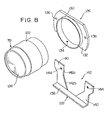
- a paper separating channel 94 is formed at one side portion of the rotating drum 8, and the photosensitive member 10 is disposed inwardly of the channel 94 as in clearly shown in Figure 2.
- the copying paper P is contacted with the photosensitive member 10 in such a manner that its one side edge portion extends outwardly beyond one side edge 10a of the photosensitive member 10 by a predetermined width w 1 and is positioned in an area where the channel 94 is formed, i.e. a nonimage area for paper separation.
- the action of a peeling nail-like member 96 ( Figure 1) projecting from the channel permits accurate separation of the copying paper P from the photosensitive member 10.
- the image of the original document O is projected onto the rotating drum 8 in register with the widthwise position of the copying paper P with respect to the rotating drum as shown by solid lines in Figure 2.
- the image of the original document O is projected substantially at a ratio of 1 onto the rotating drum such that one side edge portion of the image of the document O extends beyond the side edge 10a of the photosensitive member 10 by the predetermined width w 1 and is thus located at a nonimage area for paper separation where the channel 94 is formed.
- the portion having the width w 1 of one side edge portion of the original document O is located correspondingly to the predetermined width w 1 of one side edge portion of the copying paper P and forms a nonimage area in which a copied image is not formed on the copying paper P.
- the predetermined width w 1 of one side edge of the original document is usually a white background having no image to be copied, no particular inconvenience is caoused if that portion becomes a non-copying portion.
- the image of the original document O is positioned widthwise such that a portion having the predetermined width w 1 of one side edge portion of the projected image on the rotating drum 8 extends beyond the side edge 10a of the photosensitive member 10 and is positioned in a nonimage area for paper separation in which the channel 94 is formed.
- the width of one side edge portion of the copying paper P' in which no copied image is formed is w 1 as in the case of equal scale copying.
- This is unnatural in that while the non-copying width of one side edge portion of the original document 0 is w 1 in the case of substantially equal scale copying, it is w 2 (w 2 w 1 /M) when the copying process is performed at a length ratio of M.
- the above disadvantages can be overcome by performing the copying process such that irrespective of the ratio of copying, only that portion having a predetermined width w 1 at one side edge portion of the original document O is always projected as a non-copying portion onto a paper separating nonimage area (an area where the channel 94 is formed) constituting the supporting base.
- the projected image of the original document O on the rotating drum 8 is positioned widthwise so that the inside edge Q of the non-copying portion having the predetermined width w 1 in one side edge portion of the original document O in the case of performing substantially equal scale copying corresponds with the inside edge of the paper separating non-image area on the rotating drum 8, i.e. the one side edge 10a of the photosensitive member 10, as shown by a two-dot chain line in Figure 3.
- the other side odge 0 2 of the original document O is substantially registered with the other side edge P 2 of the copying paper P.
- that portion having a slight width w 3 at the other side edge portion of the original document O extends beyond the other side edge P21 of the copying paper P' and is not imaged as a copied image (this, houwever, will usually not give rise to any particular problem since that portion having the width w 3 in the other side edge portion of the original document 0 is usually a white background).
- the other side edge Q 2 of the original document O is located slightly inwardly of the other side edge of the copying paper.
- the other side edge R 2 of the projected image on the rotating drum 8 is registered with the other side edge P 2 ' of the copying paper P' and therefore, the other side edge 0 2 of the original document 0 is registered with the other side edge P 2 ' of the copying paper P', thereby forming a reduced copied image.
- the total width of the image of the original document O projected onto the rotating drum 8 is made slightly larger than the total width of the copying paper, or in other words, the ratio M"' of the total width of the projected image on the rotating drum 8 to the total width W 1 of the original document is made slightly higher than the ratio of the total width of the copying paper to the total width W 1 of the original document O.
- the other side edge of the projected image on the rotating drum 8 can be registered with the other side edge of the copying paper, and therefore, the other side edge 0 2 of the original document O can be registered with the other side edge of the copying paper, thereby forming an enlarged copied image.
- the copying apparatus of the invention illustrated in Figure 1 is constructed such that it can perform a copying process at two or more selectively prescribed ratios, more specifically in a substantially equal scale mode or in a reduced scale mode at a predetermined ratio (for example, about 0.7 in length and about 0.5 in area).
- a predetermined ratio for example, about 0.7 in length and about 0.5 in area.
- the optical device 66 projects the image of an original document placed on the transparent plate 4 onto the photosensitive member 10 disposed on the peripheral surface of the rotating drum 8 substantially at a ratio of 1.
- the optical device 66 projects the image of the original document placed on the transparent plate 4 at the above-mentioned predetermined ratio onto the photosensitive member 10 disposed on the peripheral surface of the rotating drum 8.
- the constituent elements of the optical device 66 are positioned as shown in Figure 1.
- some of the constituent elements of the optical device 66 in the illustrated embodiment, the lens assembly 78, the second reflecting mirror 74 and the third reflecting mirror 76) are moved as prescribed.
- the lens assembly 78 is moved in a direction inclined at a predetermined angle to the optical axis of the optical device 66, and is thus caused to approach the photosensitive member 10,-in order to position the reduced projected image, for example, as described hereinabove with reference to Figure 3 or 4 with respect to the photosensitive member 10.
- a pair of upstanding pieces 104 formed at one side portion of the supporting frame 102 for the lens assembly 78 are slidably mounted on the inclined guide rod 98.
- the under surface of a main portion 106 of the supporting frame 102 is separated some distance from the upper surface of the horizontal base plate 6, and at the under surface of the main portion 106 is formed a supporting block 108 which is in contact with the upper surface of the horizontal base plate 6 and when the supporting frame 102 is moved along the inclined guide rod 98, is caused to slide over the upper surface of the horizontal base plate 6.
- the supporting frame 102 is accurately supported in the desired condition when its pair of upstanding pieces 104 are mounted on the inclined guide rod 98 and the supporting block 108 comes into contact with the upper surface of the horizontal base plate 6.
- a position-setting member 110 is also fixed to the horizontal base plate 6, and upstanding stop pieces 112a and 112b are formed at opposite ends of the position-setting member 110.
- the optical device 66 projects the image of an original document substantially at a ratio of 1 onto the photosensitive member 10
- the edge of a projecting piece 114 formed at one side portion of the supporting frame 102 abuts against the stop piece 112b as shown in Figures 5 and 6.
- detecting switches Sl and S2 for detecting the permanent magnet 120 are provided on the horizontal base plate 6. Furthermore, as will be described in greater detail hereinafter, the detecting switch Sl detects the permanent magnet 120 when the supporting frame 102 is held at the aforesaid equal scale position or its vicinity, and the detecting switch S2 detects the permanent magnet 120 when the supporting frame 102 is held at the aforesaid reduced scale position or its vicinity.
- the lens assembly 78 of the optical device 66 is mounted on the supporting frame 102 as prescribed.
- the mechanism of mounting the lens assembly 78 on the supporting frame 102 will be described with reference to Figures 8 and 9 taken in conjunction with Figure 6.
- the lens assembly 78 is comprised of a substantially hollow cylindrical lens housing 122, and one or more (usually a plurality of) lenses 124 placed in the lens housing 122.
- a linking member 126 and a supporting member 128 are used in the illustrated embodiment.
- the linking member 126 has a hollow cylindrical portion 130 having an inside diameter corresponding to the outside diameter of the lens housing 122 of the lens assembly 78 and a flange portion 132 projecting from the cylindrical portion 130 radially toward both sides.
- a radially extending screw hole 134 is formed in the cylindrical portion 130, and a pair of axially extending screw holes 136 are formed in the flange portion 132.
- the linking member 126 is fixed to the lens assembly 78 by fitting it over a given position of the central part of the lens housing 122, threadably inserting a setscrew (not shown) through the screw hole 134, and causing the end of the setscrew to abut against the surface of the lens housing 122, or threadably fitting it with a corresponding screw hole (not shown) formed in the lens housing 122.
- the supporting member 128 has a base portion 138 and a projecting supporting piece 140 upstanding from the base portion 138.
- a relatively large notch 142 extending from its upper end edge to its lower end edge.
- the notch 142 has an introductory portion 142a extending downwardly from the upper end edge of the projecting supporting piece 140 with a slightly larger width than the outside diameter of the cylindrical portion 130 of the linking member 126 and a tapering portion 142b extending downwardly from the introductory portion 142a in a tapering manner.
- a pair of through-holes 144 located on the opposite sides of the notch 142 are formed in the projecting supporting piece 140.
- the supporting member 128 is fixed to the supporting frame 102 by fixing its base portion 138 to the upper surface of the main portion 106 of the supporting frame 102 by a suitable method such as welding or screwing.
- the lens assembly 78 In mounting the lens assembly 78 having the linking member 126 fixed thereto on the supporting frame 102 having the supporting member 128 fixed thereto, the lens assembly 78 is inserted through the introductory portion 142a of the notch 142 and set on the tapering portion 142b, and as shown in Figure 9, the peripheral surface of the cylindrical portion 130 of the linking member 126 is placed on the side edges of the tapering portion 142b. Then, the flat one surface of the flange portion 132 of the linking member 126 is contacted with the adjoining flat one surface of the projecting supporting piece 140. Set screws 146 are screwed into the pair of screw holes 136 formed in the flange portion 132 of the linking member.126 through the'pair of through-holes 144 formed in the projecting supporting piece 140.
- the lens assembly 78 is fixed to the projecting supporting piece 140.
- the peripheral surface of the cylindrical portion 130 of the linking member 126 is brought substantially into point-to-point or line-to-line contact with both side edges of the tapering portion 142b of the notch 142 thereby accurately defining the vertical and lateral positions of the lens assembly 78 with respect to the supporting frame 102.
- the flat one surface of the flange portion 132 of the linking member 126 is contacted with the adjoining one flat surface of the projecting supporting piece 140, thereby accurately defining the axial position of the lens assembly 78 with respect to the supporting frame 102 and also accurately positioning the axis of the lens assembly 78 with respect to the supporting frame 102 as prescribed (more specifically, so that it extends perpendicularly to the projecting supporting piece 140).
- the lens assebly 78 can be mounted as prescribed onto the supporting frame 102 with relative simplicity and ease.
- a projecting piece 148 is formed at one end portion (the right end portion in Figures 5 and 7) of the supporting frame 102, and an exposure adjusting plate 150 is mounted on the projecting piece 148.
- a pair of laterally spaced slots 152 are formed in the exposure adjusting plate 150.
- the exposure adjusting plate 150 is mounted on the projecting piece 148 such that its position can be freely adjusted (namely, the amount of the plate 150 projecting from the projecting piece 148 can be adjusted freely).
- the configuration, operation, effect, etc. of the exposure adjusting plate 150 itself will be described hereinafter in greater detail.
- a supporting frame 156 is also mounted on the horizontal base plate 6 ( Figures 1, 6 and 7) in addition to the supporting frame 102.
- the supporting frame 156 has a pair of laterally spaced side plates 158a and 158b and a member 160 connected between the pair of side plates 158a and 158b.
- the second reflecting mirror 74 and the third reflecting mirror 76 ( Figures 1 and 7) of the optical device 66 are mounted as prescribed between the pair of side plates 158a and 158b.
- a pair of linking brackets 162 are secured to the outside surface of the side plate 158a.
- a guide rod 166 extending substantially parallel to the optical axis of the optical device 66 is fixed to the horizontal base plate 6 ( Figures 1, 5 and 7) by means of a pair of fixing blocks 164.
- the above pair of linking brackets 162 are slidably linked to the guide rod 166.
- a short shaft 168 is fixed firmly in the inside surface of the side plate 158b, and a roller 170 above the horizontal base plate 6 is rotatably mounted on the short shaft 168 (see Figures 11-A and 11-B also).
- the supporting frame 156 can be moved along the guide rod 166 when the pair of linking brackets 162 slide with respect to the guide rod 166 and the roller 170 rotates over the horizontal base plate 6.
- the supporting frame 156 is selectively held at the equal scale position shown by a solid line in Figure 5 and also in Figure 10 (as will be stated hereinafter, when the supporting frame 156 is held at this equal scale position, the optical device 66 projects the image of an original ducument onto the photosensitive member 10 substantially at a ratio of 1), and the reduced scale position shown by a two-dot chain line in Figure 5 (as will be stated hereinafter, when the supporting frame 156 is held at this reduced scale position, the optical device 66 projects the image of the original dicument onto the photosensitive member 10 on a reduced scale at a predetermined ratio).
- the optical device 66 also has a moving mechanism shown generally at 172 for selectively holding the supporting frame 102 and the supporting frame 156 at the aforesaid equal scale position and the reduced scale position.
- a mounting member 174 having a base portion 174a fixed to the horizontal base plate 6 and a mounting portion 174b upstanding from the base portion 174a, and a drive source constructed of a reversible electric motor 176.
- the reversible motor 176 has an output shaft 178 projecting forwardly in Figure 10 through the mounting portion 174b of the mounting member 174, and the output shaft 178 constitutes an input shaft of the moving mechanism 172.
- the moving mechanism 172 further includes a first moving arrangement 180 for moving the supporting frame 102 according to the rotation of the shaft 178 and a second moving arrangement 182 for moving the supporting frame 156 according to the rotation of the shaft 178.
- the first moving arrangement 180 includes a pulley 184 fixed directly to the shaft 178, and a rope 186, conveniently a wire rope, is wrapped about the pulley 184 through nearly one turn.
- the pulley 184 is rotated between the angular position shown in Figure 11-A and the angular position shown in Figure 11-B by the reversible electric motor 176.
- the other side of the rope 186 wrapped about the pulley 184 extends along rotatably mounted guide pulleys 196 and 198 and is connected by means of a tension spring 200 to the linking piece 192 fixed to the supporting frame 102.
- the guide pulleys 190 and 198 guide the rope 186 so that it extends substantially parallel to the inclined guide rod 98 between the guide pulley 190 and the linking piece 192 and between the linking piece 192 and the guide pulley 198.
- the second moving arrangement 182 will be described with reference to Figures 11-A and 11-B taken in conjunction with Figures 5 and 10.
- the second moving arrangement 182 includes a wheel 202, conveniently a sprocket wheel, directly fixed to the shaft 178.
- a short shaft 206 is fixed to one of a pair of side plates 204 disposed in laterally spaced apart relationship within the housing 2 ( Figure 1) (the horizontal base plate 6 is disposed between this pair of side plates), and a wheel 208, conveniently a sprocket wheel, is rotatably mounted on the short shaft 206.
- a wrapping power transmission member 210 is wrapped about the wheels 202 and 208, and a cam 212 to be rotated as a unit with the wheel 208 is also mounted on the short shaft 206.
- the cam 212 is comprised of a cam plate having on its peripheral surface two arcuate acting surfaces having different radii, i.e., a small-radius acting surface 214a and a large-radius acting surface 214b, and a transit surface 214c located between the two acting surfaces on its peripheral surface.
- a fan-like member 216 is mounted on the outside surface of the side plate 158a of the supporting frame 156, and a short shaft 218 is fixed into the fan-like member 216, and a roller 220 constituting a com follower is rotatably mounted on the end portion of the short shaft 218.
- the lower end portion of the fan-like member 216 is pivotably linked to the side plate 158a by a linking pin 222 and a setscrew 226 is screwed into the side plate 158a through an arcuate slit 224 having its center at the linking pin 222.
- the fan-like member 216 is mounted on the side plate 158a so that its angular position of pivoting about the linking pin 222 as a center can be freely abjusted. It will be appreciated that when the pivoting angular position of the fan-like member 216 with respect to the side plate 158a is changed, the position of the roller 220 in the longitudinal direction of the.guide rod 166'with respect to the supporting frame 156 will be changed.
- the guide rod 166 has also mounted thereon a compression spring 228 one end of which acts on one of the pair of fixing blocks 164 and the other of which acts on one of the pair of linking brackets 162.
- the compression spring 228 elastically urges the supporting frame 156 toward the right in Figures 11-A and 11-B, and elastically presses the roller 220 constituting the cam follower against the periperal surface of the cam 212.
- the reversible electric motor 176 is rotated normally to rotate the shaft 178 in the directoin of an arrow 230 ( Figures 10 and 11-A).
- the pulley 184 of the first moving arrangement 180 is rotated in the direction of arrow 230.
- the rope 186 is moved in the direction of arrow 230, and thus the supporting frame 102 is moved in the direction of arrow 230.
- the detecting switch S2 detects the permanent magnet 120 fixed to the supporting frame 102.
- the reversible motor 176 is not deenergized; but it is deenergized after the lapse of a'predetermined delay time from the time when the detecting switch S2 detected the permanent magnet 120.
- the reversible motor 176 continues to be in the energized state for a certain period of time.
- the supporting frame 102 cannot further move in the direction of arrow 230, whereas a force tending in the direction of arrow 230 acts on the rope 186 to stretch the tension spring 194 elastically.
- the supporting frame 102 is pressed elastically against the stop piece 112a by the action of the tension spring 194 and thereby accurately held at the required reduced scale position.
- the reversible electric motor 176 is reversely rotated to rotate the shaft 178 in the direction shown by an arrow 232 ( Figures10 and 11-B).
- the pulley 184 of the first moving arrangement 180 is rotated in the direction of arrow 232.
- the rope 186 is moved in the direction of arrow 232, and as a result, the supporting frame 102 is moved in the direction of arrow 232.
- the detecting switch Sl detects the permanent magnet 120 fixed to the supporting frame 102. As described in more detail hereinafter, however, even when the detecting switch Sl has detected the permanent magnet 120, the reversible motor 176 is not deenergized; but it is deenergized after the lapse of a certain period of delay time from the time when the detecting switch Sl detected the permanent magnet 120.
- the reversible motor 176 continues to be in the energized state for a certain period of time.
- the supporting frame 102 cannot be moved further in the direction of arrow 232,. whereas a force tending in the direction of arrow 232 acts on the rope 186 to stretch the tension spring 200 elastically.
- the tesion spring 200 By the action of the tesion spring 200, the supporting frame 102 is pressed elastically against the stop piece 112b and thereby held accurately at the required equal scale position.
- the supporting frame 156 is accurately held at the required equal scale position.
- the moving mechanism 172 provided in the optical device 66 has excellent advantages, among which are:
- the illustrated copying apparatus of this invention is constructed such that the copying process can be performed at selectively prescribed two or more ratios of copying, more specifically in a substantially equal scale mode and a reduced scale mode at a predetermined ratio (e.g., about 0.7 in length and about 0.5 in area).
- a predetermined ratio e.g., about 0.7 in length and about 0.5 in area.
- Figure 12-A diagrammatically shows the projection of an original document O onto the photosensitive member 10 as a projected image I on a substantially equal scale by means of a lens L. It is well known to those skilled in that art that in the projected state shown in Figure 12-A, light from a point p on the'original document 0 which falls at an incidence angle of a to the lens L is decayed to cos 4 a times at point p' on the projected image I owing to the widthwise light decaying property of the lens L. In order, therefore, to make the distribution of illuminance in the widthwise direction at the projected image I substantially uniform by adjusting the light decaying property of the lens L, the specific illuminance Z at point p of the original document O should be adjusted to a value given by the following equation.
- the document illuminating lamp 70 ( Figures 1 and 7) of the optical device 66 in the illustrated copying apparatus is constructed such that its brightness is gradually increased from its center in the widthwise direction toward its side end as is well known, and it illuminates the document O placed on the transparent plate 4 ( Figures 1 and 7) at the illuninance defined by equation (1) above thereby to offset the widthwise decaying property of the lens L and to make the distribution of illuminance of the projected image I in the widthwise . direction substantially uniform.
- the width, in the moving direction of the photosensitive member 10 (the moving direction of the transparent plate 4), namely the slit exposure width, of a light path leading from the original document O to the photosensitive member 10 may be substantially the same along the entire width of the photosensitive member 10.
- the slit exposure width regulating member 84 ( Figures 1 and 7) defining the slit exposure width between the lens L and the photosensitive member 10 defines the slit exposure width which is substantially the same along the entire width of the photosensitive member 10.
- the lens assembly 78 of the optical device 66 in the illustrated copying apparatus is moved in a direction inclined at a predetermined angle with respect to the optical axis of the optical device 66.
- the state of projecting the original document O onto the photosensitive member 10 as a projected image I on a reduced (or enlarged) scale at a predetermined ratio M by the lens L is as shown diagrammatically in Figure 12-B.
- Figure 12-B shows the case in which as described hereinabove with reference to Figure 2, the reduced (or enlarged) projected image I is positioned widthwise such that its one side edge corresponds with one side edge of the projected image I on an equal scale (accordingly, some correction is required as described below when the projected image I is positioned widthwise as described above with reference to Figures 3 and 4).
- F is the distance from one side edge of the projected image I to the optical axis of the lens L and expressed by the following formula.
- G is the distance from one side edge of the projected image I to point p', and expressed by
- the point p' of the projected image I collects light in an amount 4/(1 + M) 2 times that in the case of the substantially equal scale projection.
- the illuminance of the point p' of the projected image I changes to the value shown'by the following eqation (3) with regard to the specific illuminance Z p(x) which is obtained in the case of the substantially equal scale projection.
- the speed of slit exposure is changed to 1/M times the speed employed in the case of the substantially equal scale copying.
- the moving speed of the transparent plate.4 (the moving speed of at least a part of the optical device in a copying apparatus of the type in which slit exposure is carried out by moving at least a part of the optical device instead of moving the transparent plate) is changed to 1/M times that employed in the case of the substantial equal scale copying. Accordingly, the exposure time changes to M times that employed in the case of the substantially equal scale copying.
- the optical slit exposure width based on the original document O is changed to 1/M times that in the case of the substantially equal scale copying according to the predetermined ratio M.
- This change in the optical slit exposure width offsets the change in the exposure time.
- the optical slit exposure width is regulated between the original document O and the lens L, the optical slit exposure width based on the original document does not change even when the ratio M changes.
- the specific illuminance at p' of the projected image I changes to the value shown by the following equation (4) as compared with the case of the substantially equal scale copying.
- the specific illuminance Z p'(x) of point p' of the projected image I projected at a predetermined ratio M changes to the value expressed by the following equation (5) as compared with the case of the substantially equal scale copying because of the changes represented by the above equations (2) and (3).
- the illuminance changes to the value given by the following equation (6) as compared with the case of the substantially equal scale copying because of the changes expressed by the above equations (2), (3) and (4).
- the illuminance of the projected image I in the widthwise direction is made substantially uniform in the following manner.
- an exposure adjusting plate 150 ( Figures 5, 6 and 7) is positioned in the light path between the lens L and the projected image I on the photosensitive member 10 or between the original document O and the lens L so as to change the slit exposure width; consequently, the amount of exposure of the point p' on the projected image I is made substantially the same as that in the case of the substantially equal scale copying. In other words, by changing the slit exposure width,the amount of exposure of the point p' on the projected image I is adjusted to
- the amount of decrease (or increase) of the slit exposure width for providing the aforesaid amount of exposure can be obtained by approximate calculation by a computer made for example according to the following theory.
- a computer made for example according to the following theory.
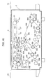
- the projected image I is equally divided into n portions (for the simplicity of description, it is divided into two equal portions in Figure 13) in the direction of the slit exposure width (the up and down direction in Figure 13), and the light leaving the lens L and forming (n+1) oblique cones arrives at the projected image I.
- a change in the total amount of light of the projected image I is determined by the ratio of the sum of the cross sectional areas of the oblique cones shut off by the exposure adjusting plate 150 to the sum total of the cross sectional areas of all oblique cones at the position at distance y. If n is taken as 2 for the simplicity of explanation, the radius r of each oblique cone at the position at distance y from the lens L is given by the following equation. Wherein N is the so-called F number of the lens L is expressed by
- H represents the length from one end (the upper end in Figure 13) of the slit exposure width at the position at distance y from the lens L to the center of each oblique cone.
- the v value can be calculated by a computer so that by making n sufficiently large, the value of S-S'/S approximates the aforesaid value (When the slit exposure width is changed between the lens L and the projected image I).
- the exposure adjusting plate 150 is mounted on the supporting frame 102 on which the lens assembly 78 of the optical device 66 is also mounted.
- the exposure adjusting plate 150 is caused to advance into the light path between the lens assembly 78 and the photosensitive member 10, more specifically between the fourth reflecting mirror 80 and the opening 82 formed in the horizontal base plate 6, and is located partly in the light path.
- the slit exposure width V regulated by the slit exposure width regulating member 84 ( Figures 1 and 7) is partly harrowed by the partial shielding action of the exposure adjusting plate 150 as shown in Figure 14 (the amount of narrowing, v, is prescribed as described above), and thus, the change in the amount of exposure expressed by equation (5) can be fully compensated for.
- the slit exposure width V employed in the substantially equal scale copying must be enlarged at least partly in order to compensate for the change in the amount of exposure expressed by equation (5) or (6) as in the case of enlarged scale copying, the restraining of at least one end of the slit exposure width by the regulating member 84 ( Figures 1 and 7) is released, and the aforesaid at least one end of the slit exposure width is regulated by the exposure adjusting plate 150 to be partly positioned in the light path.
- the exposure adjusting plate 150 is mounted on the supporting frame 102 on which the .lens assembly 78 is also mounted, and when the supporting frame 102 is moved to the position shown by the two-dot chain line in Figure 7 in order to hold the lens assembly 78 in the reduced scale position, the exposure adjusting plate 150 is necessarily positioned in the light path, and therefore, no particular moving and positioning mechanism for the exposure adjusting plate 150 is required. It should also be noted that in the illustrated copying apparatus constructed in accordance with this invention, the exposure adjusting plate 150 is caused to advance into the light path by being moved not substantially perpendicularly to the optical axis but in a direction inclined thereto by a predetermined angle Y .
- the slit exposure width can be varied with sufficient accuracy even if tolerable errors (for example, tolerable errors in the configuration of the exposure adjusting plate 150 or the incoming position of the exposure adjusting plate 150) in regard to the amount of advancing of the exposure adjusting plate 150 into the light path in the case of reduced (or enlarged) scale copying are relatively large.
- tolerable errors for example, tolerable errors in the configuration of the exposure adjusting plate 150 or the incoming position of the exposure adjusting plate 150
- Control circuit for movement of the optical device In the illustrated copying apparatus constructed in accordance with this invention, it is essential that the supporting frame 102 (and the lens assembly 78 and the exposure adjusting plate 150 mounted on it) and the supporting frame 156 (and the second reflecting mirror 74 and the third reflecting mirror 76 mounted on it) should be moved selectively from the equal scale position shown by the solid line in Figure 5 to the reduced scale position shown by the two-dot chain line in Figure' 5 or from the aforesaid reduced scale position to the aforesaid equal scale position according to the desired ratio of copying selected, more specifically according to whether the copying is carried out in a substantially equal scale mode or in a reduced scale mode at a predetermined ratio.
- this movement of the supporting frames 102 and 156 is achieved by the operation of the drive source, i.e. the reversible electric motor 176 ( Figure 5), of the moving mechanism 172.
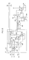
- the operation of the reversible electric motor 176 is controlled by the control circuit shown in Figure 15.
- the detecting switch Sl detects the permanent magnet 120 secured to the supporting frame 102 and produces a signal indicating the equal scale positions.
- a signal "H” is put into an input terminal 234.
- the signal "H” is fed to an AND gate 236, and consequently, the AND gate 236 produces a signal “H” and feeds it to an output terminal 238.
- a lamp Pl displaying the equal scale position which is provided, for example, in an operating panel (not shown) of the copying machine is turned on.
- the signal "H” produced by the AND gate 236 is also fed into one input terminal of an AND gate 240.
- Flip-flops 242 and 244 are reset when the power supply is set in operation.
- the detecting switch S2 does not detect the permanent magnet 120 secured to the supporting frame 102, and therefore, a signal "L” is put into an input terminal 246.
- a signal from an output terminal 248 is also "L”
- a lamp P2 displaying the reduced scale position-provided, for example, 'in the operating panel (not shown) of the copying apparatus is turned off.
- the detecting switch Sl fails to detect the permanent magnet 120 and the signal fed into the input terminal 234 becomes “L”.
- the output signal of the AND gate 236 also becomes “L”.
- the signal at the output terminal 238 also becomes “L” and the lamp P1 displaying the equal scale position is turned off.
- the detecting switch S2 detects the permanent magnet 120 to produce a signal indicating the reducing position.
- the signal "H” is then fed into an AND gate 262 after a predetermined delay time by a delay circuit 260.
- the AND gate 262 Upon the feeding of the signal "H” into the AND gate 262, the AND gate 262 outputs the signal “H” and feeds it to a clearing input terminal CL of the flip-flop 244 through an OR gate 264.
- the aforesaid output signal "L" of the OR gate 252 is also fed to the driver 254 to render it non-conducting. As a result, the supply of a current from the power supply to the relay RY is stopped to deenergaze the relay RY, and the contacts RY-1 and RY-2 of the relay RY become conducting to the terminal a.
- the output signal "H” of the AND gate 262 is also fed to the output terminal 248 to turn on the lamp P2 displaying the reduced scale position.
- the AND gate 266 when the signal "H” is fed to the above one input terminal of the AND gate 266 from the input terminal 250, the AND gate 266 produces a signal “H” and feeds it to a clock pulse input terminal CP of the flip-flop 242. Since at this time, a signal “H” is fed to the data input terminal D of the flip-flop 242 from the output terminal 5 of the flip-flop 244, a signal “H”'is produced at the output terminal Q of the flip-flop 242. This signal “H” is fed to the driver 258 through the OR gate 256 to render the driver 258 conducting.
- the detecting switch Sl detects the permanent magnet 120 to produce a signal indicating the equal scale position.
- a signal "H” is produced at the input terminal 234.
- This signal "H” is fed to the AND gate 236 after the lapse bf a predetermined delay time by a delay circuit 268.
- the AND gate 236 outputs the signal "H” and feeds it to the clearing input terminal CL of the flip-flop 242 through an OR gate 270.
- the control circuit illustrated in Figure 15 controls the motor 176 such that when the operator manually operates the change-over switch CS, the supporting frames 102 and 156 can be correspondingly moved from the equal scale positions to the reduced scale positions or vice versa.
- the control circuit shown in Figure 15 also controls the motor 176 in such a manner that when the power supply in the copying apparatus is set in operation, the supporting frames 102 and 156 will be automatically held accurately at the equal scale positoins not only when the detecting switch Sl is not in condition for detecting the permanent magnet 120 and for producing a signal indicating the equal scale position but also when it is in condition for detecting the permanent magnet 120 and producing the aforesaid signal.
- a power supply switch (not shown) provided, for example, in the operating panel (not shown) of the copying apparatus is closed, a power supply operation detecting device 274, which can be constructed, for example, of a pulse generating circuit, produces a signal.”H". over a predetermined period of time.
- the signal "H" is fed to one input terminal of the AND gate 272.
- the detecting switch Sl detects the permanent magnet 120 and produces a signal indicating the equal scale position
- the signal "H” is put into the input terminal 234, and this signal "H” is fed to the other input terminal of the AND gate 272.
- the AND gate 272 outputs the signal "H” and feeds it to the OR gate 252.
- the motor 176 is normally rotated as described in section (1) above, and the supporting frames 102 and 156 begin to be moved in the direction of arrow 230 toward the reduced scale positions.
- the detecting switch Sl no longer detects the permanent magnet 120, and the signal indicating the equal scale position disappears.
- the input signal at the input terminal 234 becomes “L”.
- the output signal of the AND gate 236 becomes “L”
- the signal "L” is reversed to "H” by an inverter 276 and then fed to one input terminal of an AND gate 278.
- the signal from the power supply operation detector 274 becomes “L”.
- This signal "L” is fed to an inverter 282, and after being reversed to "H” by the inverter 282, it is fed to a pulse generator circuit 284.
- the pulse generator circuit 284 produces a signal "H".
- the signal “H” is fed to the other input terminal of the AND gate 278. Since at this time the signal “H” from the inverter 276 is fed to the one input terminal of the AND gate 278, the output signal of the AND gate 278 becomes “H”.
- the output signal “H” of the AND gate 278 is fed to a preset input terminal PR of the flip-flop 242, whereby the flip-flop 242 produces a signal "H” at its output terminal Q.
- the signal “H” is fed to the OR gate 256, and the output signal of the OR gate 256 continues to be “H”.
- the signal "L" from the input terminal 234' is also fed to the AND gate 272, and the output signal of the AND gate 272 becomes “L".
- the output signal "L” of the AND gate 272 is fed to the OR gate 252 after the lapse of a predetermined delay time by a delay circuit 280. Since at this time the signal "L” is also fed to the OR gate 252 from the output terminal Q of the flip-flop 244, the output signal of the OR gate 252 becomes "L". As a result, the driver 254 is rendered non-conducting and the relay RY is deenergized. Upon the deenergization of the relay RY, the contacts RY-1 and RY-2 which are conducting to the terminal b become conducting to the terminal a.
- the motor 176 is reversely rotated, and the moving directions of the supporting frames 102 and 156 are reversed, and they are moved in the direction of arrow 232 toward the equal scale positions. Thereafter, the supporting frames 102 and 156 are accurately held at the equal scale positions and then the motor 176 is stopped, as described in section (2) above.
- the supporting frames 102 and 156 are located at the reduced scale positions or their vicinity (in which case the detecting switch S2 is in condition for detecting the permanent magnet 120), or they are located between the equal scale position and the reduced scale position in which case the detecting switch Sl is not in condition for detecting the permanent magnet 120.
- the power supply switch (not shown) is closed, the power supply operation detector 274 produces a signal "H” over a predetermined period of time.
- the signal of the power supply operation detector 274 becomes “L” after the lapse of the predetermined period of time, the signal "L” is reversed to "H” by the inverter 282 and then fed to the pulse generator circuit 284.
- the pulse generator circuit 284 produces a signal "H", and feeds it.to.one input terminal of the AND gate 278.
- the input signal of the input terminal 234 is "L” because the detecting switch S1 does not detect the permanent magnet 120 and therefore does not produce a signal indicating the equal scale position.
- This signal “L” is reversed to "H” by the inverter 276 and fed to the other input terminal of the AND gate 278. Accordingly, when the signal "H” is fed to one input terminal of the AND gate 278 from the pulse generator circuit 284, the AND gate 278 produces a signal "H” and feeds it to the present input terminal PR of the flip-flop 242.
- the flip-flop 242 produces a signal "H” at its output terminal Q, and feeds it to the OR gate 256.
- the output signal of the OR gate 256 becomes "H"
- the driver 258 becomes conducting.
- the motor 176 is reversely rotated as described in section (2) above, and the supporting frames 102 and 156 begin to be moved in the direction of arrow 232 toward the equal scale positions. As described in (2) above, the motor 176 is stopped after the supporting frames 102 and 156 are held accurately at the equal scale positions.
- a pair of a wheel 286 and a wheel 288, conveniently sprocket wheels, are rotatably mounted. at spaced-apart relationship in the left and right directions in Figure 16 at the upper end portion of the housing 2.
- An endless wrapping power transmission member 290 conveniently a chain, is wrapped about the wheels 286 and 288.
- a suspending piece 292 is attached to the transparent plate 4 disposed movably in the right and left directions in Figure 16 at the upper surface of the housing 2.
- an opening 294 which extends in the up-and-down direction over the upper and lower travelling sections of the power transmission member 290.
- An interlocking pin 296 formed in the wrapping power transmission member 290 is inserted in the opening 294.
- the transparent plate 4 is caused to make a preparatory movement in the right direction in Figure 16 from its stop position shown by a solid line in Figure 16 (and Figure 1) to its start-of-scan position shown by the two-dot chain line 4A in Figure 16 (and Figure 1); thereafter, to make a scanning movement in the left direction in Figure 16 from the start-of-scan position to its end-of-scan position shown by a two-dot chain line 4B in Figure 16 (and Figure 1); and thereafter, to make a return movement in the right direction from the end-of-scan position to the stop position shown by the solid line in Figure 16 (and Figure 1).
- a main drive source 300 composed of an electric motor is disposed near the left end of the housing 2 in Figure 16, and a sprocket wheel 302 is connected to the output shaft of the main drive source 300.
- the sprocket wheel 302 is drivingly connected by means of an endless chain 304 to a sprocket wheel 306 having a relatively large diameter, a sprocket wheel 308 having a relatively small diameter, an idle sprocket wheel 310, a sprocket wheel 312, a sprocket wheel 314 and an idle sprocket wheel 316.
- the sprocket wheel 306 is connected to a gear 318 through an electromagnetic clutch CL1, and the sprocket wheel 308 is connected to a gear 320 through an electromagnetic clutch CL2.
- the gear 318 is engaged with the gear 320, and the gear 320 is engaged with a gear 322 which rotates as a unit with a wheel 286 about which the wrapping power transmission member 290 is wrapped.
- the sprocket wheel 312 has affixed thereto a sprocket wheel 324 which rotates as a unit with the sprocket wheel 312.
- the sprocket wheel 324 is drivingly connected to an idle sprocket wheel 328 and a sprocket wheel 330 by means of an endless chain 326.
- the sprocket wheel 330 has affixed thereto a sprocket wheel 332 which rotates as a unit with the sprocket wheel 330.
- the sprocket wheel 332 is drivingly connected by means of an endless chain 334 to an idle sprocket wheel 336, a sprocket wheel 338, a sprocket wheel 340, a sprocket wheel 342, an idle sprocket wheel 344 and a sprocket wheel 346.
- the sprocket wheel 330 is drivingly connected to a rotating drum 8 and the operating part of a developing device 18 ( Figure 1) by a suitable drivingly connecting mechanism (not shown) such as a gear train.
- the sprocket wheel 338 has affixed thereto a gear 348 which rotates as a unit with the sprocket wheel 338.
- the gear 348 is engaged with a gear 350.
- the gear 350 is connected to a feed roller 38 ( Figure 1) through a clutch SCL1 controlled by a solenoid SL1.
- the sprocket wheel 340 is connected to lower rollers of the delivery roller unit 42 ( Figure 1) through a clutch SCL2 controlled by a solenoid SL2.
- the sprocket wheel 342 is connected to lower rollers of the conveying roller unit 46 ( Figure 1), and the-sprocket wheel 346 is connected to the roller 50 ( Figure 1).
- the sprocket 314 has affixed thereto a gear 352 which is driven as a unit with the sprocket 314.
- the gear 352 is connected successively to gears 354, 356, 358 and 360.
- the gear 354 is connected to the upper rollers of the fixing roller unit 54 ( Figure 1), and the gear 358, to the upper rollers of the conveying roller unit 58 ( Figure 1).
- the main drive source 300 is energized to rotate the sprocket wheel 302 'in the direction shown by an arrow 298, and the endless chains 304, 326 and 334 are driven in the direction of the arrow 298.
- the rotating drum 8 is rotated in the direction of arrow 12
- the conveying roller unit 46, the roller 50, the fixing roller unit 54 and the conveying roller unit 58 of the paper conveying mechanism 32 are rotated in the required directions.
- the wrapping power transmission member 290 is driven in the direction of arrow 298 at a predetermined speed V 1 (which is substantially the same as the moving speed of the photosensitive member 10 disposed on the peripheral surface of the rotating drum 8) to move the transparent plate as required.
- V 1 which is substantially the same as the moving speed of the photosensitive member 10 disposed on the peripheral surface of the rotating drum 8
- V 2 V1/M
- a copying apparatus of the type adapted to form a latent electrostatic image or a toner image on the photosensitive member 10 disposed on the peripheral surface of the rotating drum 8 by an image-forming step including the slit exposure scanning of an original document to be copied, and then transferring the latent electrostatic image or the toner image on the photoseneitive member 10 to a copying paper in the transfer zone 26, as in the copying apparatus shown in the drawings, it is important that the leading edge of the latent electrostatic image or the toner image on the photosensitive member 10 and the leading edge of the copying paper should arrive synchronously at the transfer zone 26 as prescribed.
- slit exposure scanning is carried out by moving the transparent plate 4 at a predetermined speed V 1 (which is substantially the same as the moving speed of the photosensitive member 10 disposed on the peripheral surface of the rotating drum 8).
- V 1 which is substantially the same as the moving speed of the photosensitive member 10 disposed on the peripheral surface of the rotating drum 8.
- synchronizing switches in number corresponding to the number of copying ratios to be selected are provided.
- a synchronizing switch corresponding to it functions and controls the conveying of a copying paper in the required relationship to the slit exposure scanning. Accordingly, whichever ratio of copying is chosen, the leading edge of the latent electrostatic image or the toner image formed on the photosensitive member 10 and the leading edge of the copying paper arrive substantially synchronously at the transfer zone 26.
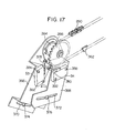
- an actuator 362 made of a suitalbe projecting piece is fixed to the wrapping power transmission member 290 to which the transparent plate 4 is drivingly connected.
- Mounting plates 366 and 368 are pivotally mounted on a supporting shaft 364 on which the wheel 288 having the wrapping power transmission member 290 wrapped thereabout is mounted rotatably.
- the mounting plates 366 and 368 respectively have arcuate slits 370 and 372 having the supporting shaft 364 as a center.
- the synchronizing switch S3 is comprised of a microswitch having a detecting arm 378 and is mounted on the mounting plate 366 so that its position can be adjusted freely.
- the synchronizing switch S4 comprised of a microswitch having a detecting arm 380 so that its position can be freely adjusted.
- the synchronizing switch S3 pivotally to the mounting plate 366 by a linking pin 382 and also by a bolt 386 extending through an arcuate slit 384 formed in the mounting plate 366 and having the linking pin 382 as a center, the synchronizing switch S3 is mounted on the mounting plate 366 so that its pivoting angular position about the linking pin 382 as a center can be freely adjusted, and therefore, its position can be freely adjusted in a direction in which the end of the detecting arm 378 moves toward and away from the wrapping power transmission member 290.
- the synchronizing switch S4 is mounted on the mounting plate 368 so that its pivoting angular position about the linking pin 388 as a center can be freely adjusted and therefore, its position can be freely adjusted in a direction in which the end of the detecting arm 380 moves toward and away from the wrapping power transmission member 290.
- the positions of the actuator 362 fixed to the wrapping power transmission member 290 at which it acts on the detecting arm 378 of the synchronizing switch S3 and the detecting arm 380 of the synchronizing switch S4 can be finely adjusted by adjusting the pivoting angular positions of the mounting plates 366 and 368 and the pivoting angular positions of the synchronizing switches S3 and S4 with respect to the mounting plates 366 and 368.
- the movement of the transmission member 290 causes the actuator 362 to operate the synchronizing switch S3, and accordingly energize the solenoid SL2.
- the delivery roller unit 42 begins to rotate and a copying paper begins to be conveyed toward the transfer zone 26.
- the movement of the transmission member 290 causes the actuator 362 to operate the synchronizing switch S4 and accordingly energize the solenoid SL2.
- the delivery roller unit 42 begins to rotate and a copying paper begins to be conveyed toward the transfer zone 26.
- the positions of the synchronizing switches S3 and S4 are prescribed as follows:
- the position of the synchronizing switch S3 is prescribed such that the copying paper is advanced from the nip position of the delivery roller unit 42 to the position n before the slit exposure scanning of an original document is started after actuation of the synchronizing switch S3 (in the illustrated copying apparatus, the slit exposure scanning of the document when the transparent plate 4 has moved a certain distance to the left in Figure 1 from the start-of-scan position shown by the two-dot chain line 4A in Figure 1).
- the position of the synchronizing switch S4 is prescribed such that the copying paper is advanced from the nip position of the conveying roller unit 42 to the position m before the slit exposure scanning of the document is started after actuation of the synchronizing switch S4.
- the conveying length t 1 of the copying paper from the position n to the center of the transfer zone 26 is substantially the same as the moving length l' 1 of the photosensitive member 10 from the upstream end of the image of the document projected on substantially the same scale onto the photosensitive member 10 to the center of the transfer zone 26.
- the conveying length t 2 of the copying paper from the position m to the center of the transfer zone 26 is substantially the same as the moving length t' 2 of the photosensitive member 10 from the upstream end of the image of the document projected on a reduced scale at the predetermined ratio M onto the photosensitive member 10 to the center of the transfer zone 26.
- the positions of the synchronizing switches S3 and S4 are prescribed so as to satisfy the following expressions.
- t 3 is the conveying distance of the copying paper from the nip position of the conveying roller unit 42 to the position n
- l 4 is the conveying length of the copying paper from the nip position of the conveying roller unit 42 to the position m
- l' 3 is the moving distance of the actuator 362 from the actuation of the synchronizing switch S3 by the actuator 362 fixed to the wrapping power transmission member 290 to the start of the slit exposure scanning
- l' 4 is the moving distance of the actuator 362 from the actuation of the synchronizing switch S4 by the actuator 362 to the start of the slit exposure scanning.
- the conveying length i of the copying paper from the nipping position of the conveying roller unit 42 to the center of the transfer zone 26 is larger than the length l' 1 or l' 2 . It will be readily seen that even when the length l is less than the length l' 1 or l' 2 , the starting of the copying conveying of a copying paper (the starting of the rotation of the conveying roller unit 42) can be controlled by the synchronizing switches S3 and S4 in the same manner as described above (in which case the actuator 362 actuates the synchronizing switch S3 or S4 after the starting of the slit exposure scanning).
- the synchronizing switches S3 and S4 control the starting of the copying paper by detecting the movement of the transparent plate 4, more specifically the movement of the wrapping power transmission member 290 to which the transparent plate 4 is drivingly connected.
- the synchronizing switch S3 or S4 may be constructed of a timer which is actuated after the lapse of a certain period of time from the starting of the movement of the transparent plate 4 from its stop position.
- the synchronizing switch S3 or S4 is made up of a timer, it is comparatively difficult to adjust the time of actuation of the synchronizing switch S3 or S4 as required.
- switches S6, S7, S8 and S9 are disposed along the moving path of the suspending piece 292 attached to the transparent plate 4."
- the switches S6, S7 and S8 are comprised of proximity switches, and detect a permanent magnet 394 fixed to the suspending piece 292 when the transparent plate 4 moves.
- the switch S9 is a microswitch and detects the actuator 396 fixed to the suspending piece 292 when the transparent plate 4 moves from left to right in Figure 16, and returns to its stop position shown by the solid line in Figure 16.
- switches S10, Sll, S12 and S13 are provided in the paper feeding and conveying passages.
- switches S10, Sll, S12 and S13 composed of microswitches detect the copying paper. Furthermore, a solenoid SL3 is attached to the cleaning device 22 as shown in Figure 1. When energized, the solenoid SL3 moves the cleaning device 22 from its nonoparative position shown by the two-dot chain line in Figure 1 and hold it at its operative position shown by the solid line in Figure 1.
- the reversible electric motor 176 in the optical device 66 is controlled as prescribed, and the supporting frames 102 and 156 are accurately held at the equal scale positions. Furthermore, as shown by a broken line in Figure 20, when the transparent plate 4 is not at its top position (the position shown by a solid line in Figures 1 and 16) and therefore the switch S9 is open, the cluthc CL1 is actuated to return the transparent plate 4 to its stop position.
- the charging corona discharging device 14 After the lapse of a certain delay time t 1 from the time of closing the switch S7, the charging corona discharging device 14 is energized, and after the lapse of a predetermined delay time t 2 , the transfer corona discharging device 20 is energized.
- the document-illuminating lamp 70 After the lapse of a predetermined delay time t 3 from the opening of the switch Sll, the document-illuminating lamp 70 is turned off, and after the lapse of a predetermined delay time t 4 , the transfer corona discharging device 20 is deenergized.
- the main drive source 300 is deenergized, the charge-eliminating lamp 64 is turned off, and the solenoid SL3 is deenergized to bring the cleaning device 22 back into its non-operative position.
- the charge-eliminating lamp 16 ( Figure 1) is turned on and off in quite the same way as the charge-eliminating lamp 64. Otherwise, the reduced scale copying is carried out by the same procedure as in the substantially equal scale copying.
Abstract
Description
- This invention relates to an electrostatic copying apparatus, and particularly to an electrostatic copying apparatus capable of giving copies at variable ratios including enlargement and reduction.
- Various types of electrostatic copying processes and apparatuses have recently been proposed, and come into commercial acceptance, which can copy an original document selectively at two or more ratios, for example at a ratio of 1 and on a reduced or enlarged scale at a predetermined ratio. These conventional processes and apparatuses adapted for selection of variable ratios, however, have not proved to be entirely satisfactory, and are not free from various inconveniences and defects as will be understood from the detailed description of the invention which follows with reference to the accompanying drawings.
- The present invention has been accomplished in view of the above fact, and its object is to overcome or eliminate the various inconveniences and defects of conventional electrostatic copying apparatuses capable of giving copies at variable ratios, and to improve them in various respects.
-
- Figure 1 is a simplified sectional view showing one embodiment of a copying apparatus constructed in accordance with this invention;
- Figures 2, 3 and 4 are diagrammatic views for illustrating the widthwise positioning of a projected image on a photosensitive member in the case of reduced (or enlarged) scale copying;
- Figure 5 is a partial sectional view showing the principal parts of an optical device used in the copying apparatus shown in Figure 1;
- Figure 6 is a partial perspective view showing one supporting frame of the optical device used in the copying apparatus shown in Figure 1 and its related elements;
- Figure 7 is a sectional view showing a part of the copying apparatus shown in Figure 1;
- Figure 8 is an exploded perspective view showing a lens assembly in the optical device used in the copying apparatus shown in Figure 1 and members used to mount the lens assembly;
- Figure 9 is a partial sectional view showing the mode of mounting a lens assembly in the optical device used in the copying apparatus shown in Figure 1;
- Figure 10 is a partial perspective view showing the other supporting frame of the optical device used in the copying apparatus shown in Figure 1 and its related elements;
- Figures 11-A and 11-B are partial sectional views showing the other supporting frame of the optical device used in the copying apparatus shown in Figure 1 and its related elements at the equal scale position and the reduced scale position, respectively;
- Figures 12-A, 12-B and 13 are diagrammatic views for illustrating variations in illuminance and their adjustment in the case of reduced (or enlarged) scale copying;
- Figure 14 is a top plan view of an exposure adjusting plate in the optical device used in the copying apparatus shown in Figure 1;
- Figure 15 is a circuit diagram showing a control circuit for the optical device used in the copying apparatus shown in Figure 1;
- Figure 16 is a simplified view showing a drive system used in the copying apparatus shown in Figure 1;
- Figures 17 and 18 are a partial perspective view and a partial sectional view showing the modes of mounting synchronizing switches used in the copying apparatus shown in Figure 1;
- Figure 19 is a diagrammatic view for illustrating a method of controlling transfer of a copying paper; and
- Figure 20 is a time chart showing the sequence of operations of the copying apparatus shown in Figure 1.
- With reference to the accompanying drawings, the present invention will be described in greater detail.
- The general construction of the copying apparatus of the invention capable of giving copies at variable ratios will be described at some length with reference to Figure 1 showing its one embodiment.
- The illustrated copying apparatus has a substantially parallelpipedal housing shown generally at 2. On the upper surface of the
housing 2 is disposed atransparent plate 4 on which to place an original document to be copied. Thetransparent plate 4 is supported by a supporting frame (not shown) mounted on the upper surface of thehousing 2 for free movement in the left and right directions in Figure 1. As will be described in detail, in the performance of a copying process, thetransparent plate 4 is caused to make a preparatory movement toward the right in Figure 1 from its stop position shown by solid lines in Figure 1 to its start-of-scan position shown by a two-dot chain line 4A in Figure 1; then to make a scanning movement toward the left in Figure 1 from. the start-of-scan position to its end-of-scan position shown by a two-dot chain line 4B; and thereafter to make a returning movement from the end-of-scan position to its stop position. An openable and closable document holding member (not shown) for convering thetransparent plate 4 and the document thereon is also mounted on the supporting frame (not shown) on which thetransparent plate 4 is supported. - Within the
housing 2, ahorizontal base plate 6 is disposed to divide the inside of thehousing 2 into an upper space and a lower space. Substantially centrally in the lower space is rotatably mounted a cylindrical rotatingdrum 8 constituting a supporting base for a photosensitive member, and aphotosensitive member 10 is disposed on at least a part of the peripheral surface of the rotatingdrum 8. Instead of the rotatingdrum 8, there may be used an endless belt-like element known to those skilled in the art, and thephotosensitive member 10 may be disposed on at least a part of the surface of the endless belt-like element. - Around the rotating drum rotated in the direction of an
arrow 12 are disposed successively in its rotating direction a chargingcorona discharging device 14, a charge-eliminatinglamp 16 to be operated during reduced scale copying, a developingdevice 18, a transfercorona discharging device 20 and acleaning device 22. The chargingcorona discharging device 14 charges thephotosensitive member 10 to a specified polarity substantially uniformly. Anexposure zone 24 exists between the chargingcorona discharging device 14 and the charge-eliminatinglamp 16. In theexposure zone 24, the image of the original document on thetransparent plate 4 is projected by an optical device to be described hereinbelow, thereby forming a latent electrostatic cimage on thephotosensitive member 10. As will be described hereinbelow,. the charge-eliminatinglamp 16 is operated when reduced scale copying is performed. Thelamp 16 illuminates one side portion of thephotosensitive member 10 which has been charged by thecorona discharger 14 but on which the image of the original document has not been projected in theexposure zone 24. Thus, the electric charge on this one side portion is removed. The developingdevice 18 which may be of any known form applies toner particles to the latent electrostatic image on thephotosensitive member 10 to develop it into a toner image. The transfercorona discharging device 20 applies a corona discharge to the back of a copying paper to be contacted with the surface of thephotosensitive member 10 in atransfer zone 26, thereby transferring the toner image on thephotosensitive member 10 to the copying paper. The illustratedcleaning device 22 is selectively held at its operating position shown by a solid line in Figure 1 or its non-operating position shown by a two-dot chain line. When thecleaning device 22 is held at the operating position, ablade 28 made of an elastic material is pressed against the surface of thephotosensitive member 10, and by the action of theblade 28, the residual toner particles on thephotosensitive member 10 after transfer are removed from it. - In the lower portion of the
housing 2, there are provided, a copying paper feed mechanism shown generally at 30 and a copying paper conveying mechanism shown generally at 32 for conveying a copying paper from thepaper feed mechanism 30 through thetransfer zone 26. - The illustrated
paper feed mechanism 30 is knoMnper se and comprises a cassette-receivingsection 34, apaper cassette 36 to be mounted detachably on the cassette-receivingsection 34 and afeed roller 38. Thefeed roller 38 is rotated selectively in the direction shown by an arrow 40, and feeds a plurality of sheet-like copying papers placed in the stacked state in thecassette 36 one by one to thepaper conveying mechanism 32. The illustratedpaper conveying mechanism 32 comprises adelivery roller unit 42 for receiving, and conveying, copying paper P fed from thepaper feed mechanism 30, aguide plate unit 44, aconveying roller unit 46, aguide plate unit 48 for guiding the copying paper P from theconveying roller unit 46 into thetransfer zone 26, aroller 50 for peeling off the copying paper P from thephotosensitive member 10 in thetransfer zone 26 and carrying it away from thetransfer zone 26, aguide plate 52, afixing roller unit 54, aguide plate 56, adischarge roller unit 58 and a receivingtray 60 for receiving the copying paper P discharged out of thehousing 2 from thediscahrging roller unit 58. One set of rollers in thefixing roller unit 54, i.e. those rollers which are located at its upper part, include a heating element (not shown) therein. Thus, by these rollers the surface of the copying paper P having a toner image transferred from thephotosensitive member 10 is pressed and heated to fix the toner image on the copying paper P. To thefixing roller unit 54 is attached a peeling-guide member 62 for peeling the copying paper P from the roller surface and guiding it downstream. A charge-eliminatinglamp 64 is disposed above theguide plate 52. The charge-eliminatinglamp 64 serves to irradiate light onto the paper P conveyed to theguide plate 52 and thereby erasing the charge remaining on the paper P, and also to irradiate light onto thephotosensitive member 10 in a zone between thecorona discharging device 20 and thecleaning device 22 thereby erasing the charge remaining on thephotosensitive member 10 after transfer. - In the upper space of the
housing 2 above thehorizontal base plate 6,.there is provided an optical device shown generally at 66 which projects the image of an original document placed on thetransparent plate 4 onto thephotosensitive member 10 to effect slit exposure when thetransparent plate 4 makes a scanning movement toward the left in Figure 1 from its start-of-scan position shown by the two-dot chain line 4A to its end-of-scan position shown by the two-dot chain line 4B. The illustrated optical device 66 has adocument illuminating lamp 70 for illuminating the document on thetransparent plate 4 through a documentilluminating opening 68 formed on the upper surface of thehousing 2, and for projecting the light reflected from the document onto thephotosensitive member 10, a first reflecting mirror 72, a secondreflecting mirror 74, a third reflectingmirror 76, alens assembly 78 and a fourth reflecting mirror 80. The reflecting light from the document illuminated by thelamp 70 is successively reflected by the first reflecting mirror 72, the secondreflecting mirror 74, and the third reflectingmirror 76, and then reaches the fourth reflecting mirror 80 through the lens within thelens assembly 78. It is reflected by the fourth reflecting mirror 80, and finally reaches thephotosensitive member 10 in theexposure zone 24 through anopening 82 formed in thehorizontal base plate 6. Between the opening 82 and thephotosensitive member 10 is provided acolored glass 83 known per se which compensates the color characteristics of thephotosensitive member 10. A slit exposure width- regulatingmember 84 for regulating the width, in the moving direction of the photosensitive member 10 (the moving direction of the transparent plate 4), of a light path leading to the photosensitive member, i.e. the slit exposure width, is also disposed between theopening 82 and thephotosensitive member 10. - In the illustrated copying apparatus, there are further provided a blower 86 composed of a Silocco-type fan and a
blower 88 composed of an ordinary impeller- type fan at the left side end portion of thehousing 2 in Figure 1. The blower 86 sucks air from outside thehousing 2 throughasuction hole 90 formed on the upper surface of thehousing 2, and discharges air through adischarge hole 92 formed on the left side surface of thehousing 2, thereby cooling thetransparent plate 4 heated by theilluminating lamp 70. Theblower 88, on the other hand, sucks air from the lower space of thehousing 2 below thehorizontal base plate 6 and discharges it through thedischarge hole 92 formed on the left side surface of thehousing 2, thereby preventing the heat of thefixing roller unit 54 from being transmitted to thephotosensitive member 10 and thereby from deteriorating thephotosensitive member 10. - The illustrated copying apparatus is constructed such that the copying process can be performed selectively in at least two copying ratios, for example either equal scale copying or reduced scale copying at a ratio of about 0.7 in length and about 0.5 in area is selectively carried out. This feature will be described in detail later on, and for the time being, the basic principle of variable ratio copying in the illustrated copying apparatus is briefly described below.
- In the illustrated copying apparatus, the
rotating drum 8 is rotated always at a predetermined speed irrespective of the ratio of copying. Thepaper conveying mechanism 32 also conveys the copying paper P through thetransfer zone 26 always at a predetermined speed irrespective of the ratio of copying, namely at substantially the same speed as the moving speed of thephotosensitive member 10 disposed on the peripheral surface of therotating drum 8. In contrast, thetransparent plate 4 is caused to make a scanning' movement at a speed varying according to the ratio of copying, and the optical device 66 projects the image of an original document placed on thetransparent plate 4 onto thephotosensitive member 10 at a prescribed ratio of copying. Specifically, when the copying process is performed at a ratio of substantially 1, thetransparent plate 4 is caused to make a scanning movement substantially at the same speed as the moving speed of the photosensitive member 10 (and the moving speed of the copying paper through the transfer zone 26), and the optical device 66 projects the image of the original document at a ratio of substantially 1. However, when the copying process is carried out at a predetermined ratio of copying, for example at a length ratio of M (e.g., M=about 0.7), thetransparent plate 4 is caused to make a scanning movement at a speed corresponding to VM where V is the speed employed in the case of performing equal scale copying, and consequently, the size, in the moving direction of the photosensitive member 10 (scanning direction), of a latent electrostatic image formed on thephotosensitive member 10 is reduced (or enlarged) to M times. At the same time, the optical device 66 projects the image of the original document placed on thetransparent plate 4 onto thephotosensitive member 10 at a ratio of M as a result of thelens assembly 78, second reflectingmirror 74 and third reflectingmirror 76 being moved respectively to prescribed positions as will be described in detail hereinbelow. As a result, the widthwise size of the latent electrostatic image formed on thephotosensitive member 10 is reduced (or enlarged) to M times. In this way, a latent electrostatic image reduced (or enlarged) to M times in length is formed on thephotosensitive member 10, and the reduced (or enlarged) latent electrostatic image is developed to a toner image and transferred to a copying paper. Thus, a reduced (or enlarged) copied image is obtained. - It is well known to'those'skilled in the art that in a so-called transfer-type electrostatic copying apparatus adapted to form a latent electrostatic image or a toner image on the
photosensitive member 10 disposed on the peripheral surface of therotating drum 8, and contact a copying paper P with the surface of thephotosensitive member 10 in thetransfer zone 26 thereby transferring the latent electrostatic image or the toner image on thephotosensitive member 10 to the copying paper P, the copying paper P adheres fairly strongly to the surface of thephotosensitive member 10 in thetransfer zone 26 by the action of electrostatic charge, and it is not always easy to peel off the copying paper P from thephotosensitive member 10 after transfer. In order to cope with this situation, apaper separating channel 94 is formed at one side portion of therotating drum 8, and thephotosensitive member 10 is disposed inwardly of thechannel 94 as in clearly shown in Figure 2. The copying paper P is contacted with thephotosensitive member 10 in such a manner that its one side edge portion extends outwardly beyond oneside edge 10a of thephotosensitive member 10 by a predetermined width w 1 and is positioned in an area where thechannel 94 is formed, i.e. a nonimage area for paper separation. In peeling off the paper P from thephotosensitive member 10, the action of a peeling nail-like member 96 (Figure 1) projecting from the channel permits accurate separation of the copying paper P from thephotosensitive member 10. - When substantially equal scale copying is carried out in a copying apparatus of the aforesaid construction, the image of the original document O is projected onto the
rotating drum 8 in register with the widthwise position of the copying paper P with respect to the rotating drum as shown by solid lines in Figure 2. In other words, the image of the original document O is projected substantially at a ratio of 1 onto the rotating drum such that one side edge portion of the image of the document O extends beyond theside edge 10a of thephotosensitive member 10 by the predetermined width w1 and is thus located at a nonimage area for paper separation where thechannel 94 is formed. As will be readily seen from Figure 2, therefore, the portion having the width w1 of one side edge portion of the original document O is located correspondingly to the predetermined width w1 of one side edge portion of the copying paper P and forms a nonimage area in which a copied image is not formed on the copying paper P. However, since the predetermined width w1 of one side edge of the original document is usually a white background having no image to be copied, no particular inconvenience is caoused if that portion becomes a non-copying portion. - When the copying process is perfomed at a copying ratio of M (M=W2/W1) using an original document having a total width of W1 and a copying paper P' having a total width of W2 in the conventional variable ratio electrostatic copying, the same method as in the case of performing the copying process at a copying ratio of substantially 1 is employed. Specifically, the image of the original document to be projected onto the
rotating drum 8 on a reduced (or enlarged) scale at a length ratio of M is registered with the widthwise position of the copying paper P' with respect to therotating drum 8. In other words, the image of the original document O is positioned widthwise such that a portion having the predetermined width w1 of one side edge portion of the projected image on therotating drum 8 extends beyond theside edge 10a of thephotosensitive member 10 and is positioned in a nonimage area for paper separation in which thechannel 94 is formed. When the copying process is carried out at a copying ratio in length of M in such a conventional variable ratio electrostatic copying, the width of one side edge portion of the copying paper P' in which no copied image is formed is w1 as in the case of equal scale copying. But the non-copying width of one side edge portion of the original document 0 projected onto the paper separating nonimage area of therotating drum 8 is increased (or reduced) to w2 (w2=wl/M), and the portion having the width w2 will not be converted to a copied image. This is unnatural in that while the non-copying width of one side edge portion of the original document 0 is w1 in the case of substantially equal scale copying, it is w2 (w2=w1/M) when the copying process is performed at a length ratio of M. Particularly in the case of reduced scale copying (i.e., M<1), the non-copying width at one side edge portion of the original document O which is not converted to a copied image is increased from w1 to w2 (w2=w1/M). This causes the inconvenience that not only the white background area at one side edge portion of the original document O, but also-that part of the original document O at which an image to be copied is present will not be converted to a copied image. - In an attempt to solve or eliminate the aforesaid problem or defect of the conventional variable ratio electrostatic copying, the specification of Japanese Laid-Open Patent Publication No. 28068/1980 discloses that in the case of reduced (or enlarged) scale, copying, the ratio M' of the total.width W3 of an image projected on the
rotating drum 8 to the total width W1 of the original document 0 (M'=W2/W1) is made lower (or higher) than the ratio M of the total width W2 of a copying paper to the total width W1 of the original document 0 (M=W2/W1) to provide W3=W2-w1, and the image of the original document O projected onto therotating drum 8 at a length ratio of M' is positioned widthwise while being registered with the image-forming portion (that part of one side edge portion which is other than the portion having a width wl) of the copying paper P'. By this contrivance, the entire width W1 of the original document O is imaged as a copied image in the image-forming portion (W2-w1) of the copying paper P. The method disclosed in Japanese Laid-Open Patent Publication No. 28086/1980, however, has one or more disadvantages described below. - (a) When the copying process is carried out substantially at a ratio of 1, the non-copying width w1 at one side edge portion of the original document 0 (this portion is usually a white background) is not imaged as a copied image on the copying paper P. In contrast, reduced (or enlarged) scale copying is unnatural in that a non-copying width does not exist and the entire width W1 of the original document 0 is imaged as a copied image on the image-forming portion (W2-wl) of the copying paper P' (hence, when one side edge portion of the original document is a white background, a white background having a fairly larger width than w1 occurs in one side edge portion of the copying paperP').
- (b) There is an unnatural feeling because a considerable difference exists between the ratio M of the width W2 of the copying paper P' to the width Wl of the original document O (M=W2/Wl) and the ratio M' of the width W3 of the copied image on the copying paper P' to the width W1 of the image of the original document O (M'=W3/W1).
- According to this invention, the above disadvantages can be overcome by performing the copying process such that irrespective of the ratio of copying, only that portion having a predetermined width w1 at one side edge portion of the original document O is always projected as a non-copying portion onto a paper separating nonimage area (an area where the
channel 94 is formed) constituting the supporting base. - With reference to Figure 3, this feature of the invention will be described. When the copying process is performed substantially at a ratio of 1, the image of the original document O is projected on the
rotating drum 8 while it is registered with the widthwise position of the copying paper P with respect to the rotating drum as in the conventional practice, as shown by a solid line in Figure 3. Hence, as in the conventional practice, that portion having a predetermined width W1 at one side edge portion of the original document O is projected onto the paper separating nonimage area (the area in which thechannel 94 is formed) on therotating drum 8 while it is located correspondingly to the predetermined width w of one side edge portion of the copying paper P; and thus it becomes a non-copying portion which is not imaged as a copied image on the copying paper P. - On the other hand, when the copying process is performed in a reduced (or enlarged) mode at a length ratio of M (M=W2/W1), the projected image of the original document O on the
rotating drum 8 is positioned widthwise so that the inside edge Q of the non-copying portion having the predetermined width w1 in one side edge portion of the original document O in the case of performing substantially equal scale copying corresponds with the inside edge of the paper separating non-image area on therotating drum 8, i.e. the oneside edge 10a of thephotosensitive member 10, as shown by a two-dot chain line in Figure 3. Thus, only that portion having the predetermined width w1 in one side edge portion of the original is always projected onto the paper-separating nonimage area of therotating drum 8 irrespective of the ratio of copying. It will thus be appreciated easily by reference to Figure 3 that in performing the copying process in a reduced (or enlarged) mode, only that portion having the predetermined width w1 in one side edge portion of the original document O is located within a portion of the predetermined width w1 in one side edge portion of the copying paper P or P' as in the case of performing substantially equal scale copying, and the non-copying width at one side edge portion of the original document O is always maintained at the predetermined vlue w1 irrespective of the ratio of copying. Accordingly, unnaturalness does not occur even in the case of reduced (or enlarged) scale copying. - On the other hand, if the image of the original document O projected on the
rotating drum 8 at a length ratio of M (M=W2/W1) as shown by a two-dot chain line in Figure 3, one side edge R1 of the projected image on therotating drum 8 is located inwardly (outwardly in an enlarging copying mode) of one side edge P'1 of the copying paper P' always positioned in place with respect to therotating drum 8 by a slight width x. - Hence, when in a reduced (or enlarged) copying mode a copying paper P' having the same total width W2 as the total width W2 of the projected image on the
rotating drum 8 is used or in other words the ratio M of the width W2 of the copying paper used to the total width W1 of the original document O (M=W2/W1) is made ' substantially the same as the ratio M of the total width W2 of the projected image on therotating drum 8 to the total width WI of the original document 0 (M=W2/W1), the other side edge R2 of the projected image on therotating drum 8 is located outwardly (inwardly in an enlarged copying mode) of the other side edge P2 1 of the copying paper P' by a slight width x, as illustrated in Figure 3. For this reason, when substantially equal scale copying is carried out, the other side odge 02 of the original document O is substantially registered with the other side edge P2 of the copying paper P. But in a reduced copying mode, that portion having a slight width w3 at the other side edge portion of the original document O extends beyond the other side edge P21 of the copying paper P' and is not imaged as a copied image (this, houwever, will usually not give rise to any particular problem since that portion having the width w3 in the other side edge portion of the original document 0 is usually a white background). In an enlarging copying mode, the other side edge Q2 of the original document O is located slightly inwardly of the other side edge of the copying paper. - This minor inconvenience may be removed by adjusting the total width of the image of the original document O projected on the
rotating drum 8 to W4 which is slightly smaller than the total width W2 of the copying paper P', or in other words, by making the ratio M" of the total width W4 of the projected image on therotating drum 8 to the total width W1 of the original document O slightly lower than the ratio M of the total width W2 of the copying paper P' to the total width W1 of the original document 0 (M=W2/W1). As will be seen from Figure 4, the other side edge R2 of the projected image on therotating drum 8 .is registered with the other side edge P2' of the copying paper P' and therefore, the other side edge 02 of the original document 0 is registered with the other side edge P2' of the copying paper P', thereby forming a reduced copied image. In an enlarged scale copying moade, the total width of the image of the original document O projected onto therotating drum 8 is made slightly larger than the total width of the copying paper, or in other words, the ratio M"' of the total width of the projected image on therotating drum 8 to the total width W1 of the original document is made slightly higher than the ratio of the total width of the copying paper to the total width W1 of the original document O. As a result, the other side edge of the projected image on therotating drum 8 can be registered with the other side edge of the copying paper, and therefore, the other side edge 02 of the original document O can be registered with the other side edge of the copying paper, thereby forming an enlarged copied image. - If the above method described with reference to Figure 4 is employed, there will of course be some difference between the ratio M of the width W2 of the copying paper P' to the width W1 of the original document O and the ratio M"(M"') of the copied image formed on the copying paper P' to the image of the original document O. Since, however, such a difference corresponds to the slight width x mentioned above and is extremely small, it does not render the copied image unnatural. In contrast, since the corresponding difference in the method disclosed in the above-cited Japanese Laid-Open Patent Publication No. 28086/1980 corresponds to a predetermined width w1 (wl x), it is considerably large and renders the copied image unnatural.
- The copying apparatus of the invention illustrated in Figure 1 is constructed such that it can perform a copying process at two or more selectively prescribed ratios, more specifically in a substantially equal scale mode or in a reduced scale mode at a predetermined ratio (for example, about 0.7 in length and about 0.5 in area). As already stated hereinabove, when the copying process is performed in a substantially equal scale mode, the optical device 66 projects the image of an original document placed on the
transparent plate 4 onto thephotosensitive member 10 disposed on the peripheral surface of therotating drum 8 substantially at a ratio of 1. In a reduced scale mode at a predetermined ratio of copying, the optical device 66 projects the image of the original document placed on thetransparent plate 4 at the above-mentioned predetermined ratio onto thephotosensitive member 10 disposed on the peripheral surface of therotating drum 8. - When the image of the original document placed on the
transparent plate 4 is to be projected onto thephotosensitive member 10 substantially at a ratio of 1, the constituent elements of the optical device 66 are positioned as shown in Figure 1. In contrast, when the image of the original document placed on thetransparent plate 4 is to be projected on a reduced scale at a predetermined ratio onto thephotosensitive member 10, some of the constituent elements of the optical device 66 (in the illustrated embodiment, thelens assembly 78, the second reflectingmirror 74 and the third reflecting mirror 76) are moved as prescribed. Thelens assembly 78 is moved in a direction inclined at a predetermined angle to the optical axis of the optical device 66, and is thus caused to approach thephotosensitive member 10,-in order to position the reduced projected image, for example, as described hereinabove with reference to Figure 3 or 4 with respect to thephotosensitive member 10. The second reflectingmirror 74 and the third reflectingmirror 76 are moved away slightly from thelens assembly 78 so that even when thelens assembly 78 is caused to approach thephotosensitive member 10, the focal distance f of the lens placed in thelens assembly 78, the distance a between the lens and the original document placed on thetransparent plate 4, and the distance b between the lens and thephotosensitive member 10 are maintained in therelation 1/f=l/a + 1/b. - One example each of mounting and moving mechanisms for achieving the change of the positions of some of the constituent elements of the optical device 66 (in the illustrated embodiment, the
lens assembly 78, the second reflectingmirror 74 and the third reflecting mirror 76) according to the ratio of copying will be described below with reference to Figures 5, 6 and 7 taken in conjunction with Figure 1. To the upper surface of the horizontal base plate 6 (Figures 1, 6 and 7) disposed within the housing 2 (Figure 1) is fixed by means of a pair of mountingblocks 100 aninclined guide rod 98 extending inclinedly at an angle 6 (Figure 5) with respect to the optical axis of the optical device 66 which extends in the left and right directions in Figures 1, 5 and 7. A pair ofupstanding pieces 104 formed at one side portion of the supportingframe 102 for thelens assembly 78 are slidably mounted on theinclined guide rod 98. As can be seen from Figure 7, the under surface of amain portion 106 of the supportingframe 102 is separated some distance from the upper surface of thehorizontal base plate 6, and at the under surface of themain portion 106 is formed a supportingblock 108 which is in contact with the upper surface of thehorizontal base plate 6 and when the supportingframe 102 is moved along theinclined guide rod 98, is caused to slide over the upper surface of thehorizontal base plate 6. Hence, the supportingframe 102 is accurately supported in the desired condition when its pair ofupstanding pieces 104 are mounted on theinclined guide rod 98 and the supportingblock 108 comes into contact with the upper surface of thehorizontal base plate 6. In relation to the supportingframe 102, a position-settingmember 110 is also fixed to thehorizontal base plate 6, andupstanding stop pieces member 110. When the supportingframe 102 is held at the equal scale position shown by a solid line in Figures 5 to 7 (as will be described below, when the supportingframe 102 is held at this equal scale position, the optical device 66 projects the image of an original document substantially at a ratio of 1 onto the photosensitive member 10), the edge of a projectingpiece 114 formed at one side portion of the supportingframe 102 abuts against thestop piece 112b as shown in Figures 5 and 6. On the other hand, when the supportingframe 102 is held at the reduced scale position shown by a two-dot chain line in Figures 5 and 7 (as will be stated below, when the supportingframe 102 is held at this reduced scale position, the optical device 66 projects the image of the original dicument on a reduced scale at a predetermined ratio onto the photosensitive member 10), a part 116 (Figure 6) of the front edge of themain portion 106 of the supportingframe 102 abuts against thestop piece 112a. A projectingpiece 118 is formed at the other side edge portion of the supportingframe 102, and apermanent magnet 120 is fixed to the under surface of the projectingpiece 118. In relation to thepermanent magnet 120, detecting switches Sl and S2 for detecting thepermanent magnet 120 are provided on thehorizontal base plate 6. Furthermore, as will be described in greater detail hereinafter, the detecting switch Sl detects thepermanent magnet 120 when the supportingframe 102 is held at the aforesaid equal scale position or its vicinity, and the detecting switch S2 detects thepermanent magnet 120 when the supportingframe 102 is held at the aforesaid reduced scale position or its vicinity. - The
lens assembly 78 of the optical device 66 is mounted on the supportingframe 102 as prescribed. The mechanism of mounting thelens assembly 78 on the supportingframe 102 will be described with reference to Figures 8 and 9 taken in conjunction with Figure 6. Thelens assembly 78 is comprised of a substantially hollowcylindrical lens housing 122, and one or more (usually a plurality of)lenses 124 placed in thelens housing 122. In order to mount thelens assembly 78 on the supportingframe 102 as prescribed, a linkingmember 126 and a supportingmember 128 are used in the illustrated embodiment. The linkingmember 126 has a hollowcylindrical portion 130 having an inside diameter corresponding to the outside diameter of thelens housing 122 of thelens assembly 78 and aflange portion 132 projecting from thecylindrical portion 130 radially toward both sides. A radially extendingscrew hole 134 is formed in thecylindrical portion 130, and a pair of axially extendingscrew holes 136 are formed in theflange portion 132. The linkingmember 126 is fixed to thelens assembly 78 by fitting it over a given position of the central part of thelens housing 122, threadably inserting a setscrew (not shown) through thescrew hole 134, and causing the end of the setscrew to abut against the surface of thelens housing 122, or threadably fitting it with a corresponding screw hole (not shown) formed in thelens housing 122. On the other hand, the supportingmember 128 has abase portion 138 and a projecting supportingpiece 140 upstanding from thebase portion 138. In the projecting supportingpiece 140 is formed a relativelylarge notch 142 extending from its upper end edge to its lower end edge. Thenotch 142 has anintroductory portion 142a extending downwardly from the upper end edge of the projecting supportingpiece 140 with a slightly larger width than the outside diameter of thecylindrical portion 130 of the linkingmember 126 and a taperingportion 142b extending downwardly from theintroductory portion 142a in a tapering manner. A pair of through-holes 144 located on the opposite sides of thenotch 142 are formed in the projecting supportingpiece 140. The supportingmember 128 is fixed to the supportingframe 102 by fixing itsbase portion 138 to the upper surface of themain portion 106 of the supportingframe 102 by a suitable method such as welding or screwing. In mounting thelens assembly 78 having the linkingmember 126 fixed thereto on the supportingframe 102 having the supportingmember 128 fixed thereto, thelens assembly 78 is inserted through theintroductory portion 142a of thenotch 142 and set on the taperingportion 142b, and as shown in Figure 9, the peripheral surface of thecylindrical portion 130 of the linkingmember 126 is placed on the side edges of the taperingportion 142b. Then, the flat one surface of theflange portion 132 of the linkingmember 126 is contacted with the adjoining flat one surface of the projecting supportingpiece 140. Setscrews 146 are screwed into the pair of screw holes 136 formed in theflange portion 132 of the linking member.126 through the'pair of through-holes 144 formed in the projecting supportingpiece 140. Thus, thelens assembly 78 is fixed to the projecting supportingpiece 140. According to the above-described mounting mechanism using the linkingmember 126 and the supportingmember 128, the peripheral surface of thecylindrical portion 130 of the linkingmember 126 is brought substantially into point-to-point or line-to-line contact with both side edges of the taperingportion 142b of thenotch 142 thereby accurately defining the vertical and lateral positions of thelens assembly 78 with respect to the supportingframe 102. Furthermore, the flat one surface of theflange portion 132 of the linkingmember 126 is contacted with the adjoining one flat surface of the projecting supportingpiece 140, thereby accurately defining the axial position of thelens assembly 78 with respect to the supportingframe 102 and also accurately positioning the axis of thelens assembly 78 with respect to the supportingframe 102 as prescribed (more specifically, so that it extends perpendicularly to the projecting supporting piece 140). Accordingly, without expertise, thelens assebly 78 can be mounted as prescribed onto the supportingframe 102 with relative simplicity and ease. If desired, it is possible to form the linkingmember 126 as a unit with thelens housing 122 of thelens assembly 78 and to form the projecting supportingpiece 140 as a unit with the supportingframe 102. It is also possible to omit thecylindrical portion 130 of the linkingmember 126 and to place the peripheral surface of thelens housing 122 directly onto the taperingportion 142b of thenotch 142 in the projecting supportingmember 140. - As shown in Figures 5, 6 and 7, a projecting
piece 148 is formed at one end portion (the right end portion in Figures 5 and 7) of the supportingframe 102, and anexposure adjusting plate 150 is mounted on the projectingpiece 148. A pair of laterally spaced slots 152 (only one of them is shown in Figure 6) are formed in theexposure adjusting plate 150. By screwingsetscrews 154 into the projectingpiece 148 through theseslots 152, theexposure adjusting plate 150 is mounted on the projectingpiece 148 such that its position can be freely adjusted (namely, the amount of theplate 150 projecting from the projectingpiece 148 can be adjusted freely). The configuration, operation, effect, etc. of theexposure adjusting plate 150 itself will be described hereinafter in greater detail. - With reference to Figures 5 and 10, a supporting
frame 156 is also mounted on the horizontal base plate 6 (Figures 1, 6 and 7) in addition to the supportingframe 102. The supportingframe 156 has a pair of laterally spacedside plates member 160 connected between the pair ofside plates mirror 74 and the third reflecting mirror 76 (Figures 1 and 7) of the optical device 66 are mounted as prescribed between the pair ofside plates brackets 162 are secured to the outside surface of theside plate 158a. On the other hand, aguide rod 166 extending substantially parallel to the optical axis of the optical device 66 is fixed to the horizontal base plate 6 (Figures 1, 5 and 7) by means of a pair of fixing blocks 164. The above pair of linkingbrackets 162 are slidably linked to theguide rod 166. Ashort shaft 168 is fixed firmly in the inside surface of theside plate 158b, and aroller 170 above thehorizontal base plate 6 is rotatably mounted on the short shaft 168 (see Figures 11-A and 11-B also). The supportingframe 156 can be moved along theguide rod 166 when the pair of linkingbrackets 162 slide with respect to theguide rod 166 and theroller 170 rotates over thehorizontal base plate 6. As will be described in greater detail, the supportingframe 156 is selectively held at the equal scale position shown by a solid line in Figure 5 and also in Figure 10 (as will be stated hereinafter, when the supportingframe 156 is held at this equal scale position, the optical device 66 projects the image of an original ducument onto thephotosensitive member 10 substantially at a ratio of 1), and the reduced scale position shown by a two-dot chain line in Figure 5 (as will be stated hereinafter, when the supportingframe 156 is held at this reduced scale position, the optical device 66 projects the image of the original dicument onto thephotosensitive member 10 on a reduced scale at a predetermined ratio). - The optical device 66 also has a moving mechanism shown generally at 172 for selectively holding the supporting
frame 102 and the supportingframe 156 at the aforesaid equal scale position and the reduced scale position. - As shown in Figures 5 and 10, provided on the horizontal base plate 6 (Figures 1, 6 and 7) is a mounting
member 174 having a base portion 174a fixed to thehorizontal base plate 6 and a mounting portion 174b upstanding from the base portion 174a, and a drive source constructed of a reversibleelectric motor 176. In the illustrated embodiment, thereversible motor 176 has anoutput shaft 178 projecting forwardly in Figure 10 through the mounting portion 174b of the mountingmember 174, and theoutput shaft 178 constitutes an input shaft of the movingmechanism 172. Needless to say, it is possible, if desired, to mount a separate input shaft for the movingmechanism 172 rotatably, and drivingly connect the input shaft to thereversible motor 176. The movingmechanism 172 further includes a first movingarrangement 180 for moving the supportingframe 102 according to the rotation of theshaft 178 and a second movingarrangement 182 for moving the supportingframe 156 according to the rotation of theshaft 178. - With reference to Figures 5 and 10 taken in conjunction with Figure 6, the first moving
arrangement 180 includes apulley 184 fixed directly to theshaft 178, and arope 186, conveniently a wire rope, is wrapped about thepulley 184 through nearly one turn. As will be described hereinafter, thepulley 184 is rotated between the angular position shown in Figure 11-A and the angular position shown in Figure 11-B by the reversibleelectric motor 176. Conveniently, in order to prevent generation of slippage between thepulley 184 and therope 186 during this rotation of thepulley 184, that part of therope 186 which does not separate from thepulley 184 is accurately fixed to thepulley 184 by means of a setscrew 188 (Figures 11-A and 11-B). One side of therope 186 wrapped about thepulley 184 extends along a rotatably mountedguide pulley 190 and is connected by means of atension spring 194 to alinking piece 192 fixed to the projectingpiece 114 formed at one side portion of the supportingframe 102. The other side of therope 186 wrapped about thepulley 184 extends along rotatably mounted guide pulleys 196 and 198 and is connected by means of atension spring 200 to thelinking piece 192 fixed to the supportingframe 102. The guide pulleys 190 and 198 guide therope 186 so that it extends substantially parallel to theinclined guide rod 98 between theguide pulley 190 and thelinking piece 192 and between the linkingpiece 192 and theguide pulley 198. - The second moving
arrangement 182 will be described with reference to Figures 11-A and 11-B taken in conjunction with Figures 5 and 10. The second movingarrangement 182 includes awheel 202, conveniently a sprocket wheel, directly fixed to theshaft 178. Ashort shaft 206 is fixed to one of a pair ofside plates 204 disposed in laterally spaced apart relationship within the housing 2 (Figure 1) (thehorizontal base plate 6 is disposed between this pair of side plates), and awheel 208, conveniently a sprocket wheel, is rotatably mounted on theshort shaft 206. A wrappingpower transmission member 210, conveniently a chain, is wrapped about thewheels cam 212 to be rotated as a unit with thewheel 208 is also mounted on theshort shaft 206. Thecam 212 is comprised of a cam plate having on its peripheral surface two arcuate acting surfaces having different radii, i.e., a small-radius acting surface 214a and a large-radius acting surface 214b, and atransit surface 214c located between the two acting surfaces on its peripheral surface. A fan-like member 216 is mounted on the outside surface of theside plate 158a of the supportingframe 156, and ashort shaft 218 is fixed into the fan-like member 216, and aroller 220 constituting a com follower is rotatably mounted on the end portion of theshort shaft 218. The lower end portion of the fan-like member 216 is pivotably linked to theside plate 158a by a linkingpin 222 and asetscrew 226 is screwed into theside plate 158a through anarcuate slit 224 having its center at the linkingpin 222. As a result, the fan-like member 216 is mounted on theside plate 158a so that its angular position of pivoting about the linkingpin 222 as a center can be freely abjusted. It will be appreciated that when the pivoting angular position of the fan-like member 216 with respect to theside plate 158a is changed, the position of theroller 220 in the longitudinal direction of the.guide rod 166'with respect to the supportingframe 156 will be changed. In relation to the supportingframe 156, theguide rod 166 has also mounted thereon acompression spring 228 one end of which acts on one of the pair of fixingblocks 164 and the other of which acts on one of the pair of linkingbrackets 162. Thecompression spring 228 elastically urges the supportingframe 156 toward the right in Figures 11-A and 11-B, and elastically presses theroller 220 constituting the cam follower against the periperal surface of thecam 212. - The operation of the moving
mechanism 172 described hereinabove is summarized below. - For example, in moving the supporting
frames electric motor 176 is rotated normally to rotate theshaft 178 in the directoin of an arrow 230 (Figures 10 and 11-A). As a result, thepulley 184 of the first movingarrangement 180 is rotated in the direction ofarrow 230. When thepulley 184 is rotated in the direction ofarrow 230, therope 186 is moved in the direction ofarrow 230, and thus the supportingframe 102 is moved in the direction ofarrow 230. When the supportingframe 102 is moved to the reduced scale position shown by the two-dot chain line in Figure 5, the part 116 of the front edge of themain portion 106 of the supportingframe 102 is caused to abut against thestop piece 112a. On the other hand, when the supportingframe 102 is moved to the reduced scale position or its vicinity, the detecting switch S2 detects thepermanent magnet 120 fixed to the supportingframe 102. As will be described in detail hereinafter, even when the detecting switch S2 has detected thepermanent magnet 120, thereversible motor 176 is not deenergized; but it is deenergized after the lapse of a'predetermined delay time from the time when the detecting switch S2 detected thepermanent magnet 120. Accordingly, after the supportingframe 102 has abutted against thestop piece 112a, thereversible motor 176 continues to be in the energized state for a certain period of time. As a result, the supportingframe 102 cannot further move in the direction ofarrow 230, whereas a force tending in the direction ofarrow 230 acts on therope 186 to stretch thetension spring 194 elastically. Thus, the supportingframe 102 is pressed elastically against thestop piece 112a by the action of thetension spring 194 and thereby accurately held at the required reduced scale position. - When the reversible
electric motor 176 is normally rotated to rotate theshaft 178 in the direction of arrow 230 (Figures 10 and 11-A), thewheel 202 of the second movingarrangement 182 is also rotated in the direction ofarrow 230, and thewheel 208 is rotated in the direction ofarrow 230 through the wrappingpower transmission member 210. Incident to the rotation of thewheel 208, thecam 212 is rotated in the direction ofarrow 230 from the position shown in Figure 11-A, and when thereversible motor 176 is deenergized, thecam 212 is held at its angular position at which the large-radius acting surface 214b acts on theroller 220 forming the cam follower, as shown in Figure 11-B. When thecam 212 is rotated from the angular position shown in Figure 11-A to the angular position shown in Figure 11-B, the action of thecam 212 causes the supportingframe 156 to move from the equal scale position shown in Figure 11-A to the reduced scale position shown in Figure 11-B against the elastic biasing action of thecompression spring 228, and is thus held accurately at the reduced scale position shown in Figure 11-B. When thereversible motor 176 is deenergized, thecam 212 needs not to be precisely held at its predetermined angular position, and so long as the large-radius acting surface 214b of thecam 212 is positioned in an angular range in which it acts on theroller 220, the supportingframe 156 is accurately held in the required reducing position. - In moving the supporting
frames electric motor 176 is reversely rotated to rotate theshaft 178 in the direction shown by an arrow 232 (Figures10 and 11-B). As a result, thepulley 184 of the first movingarrangement 180 is rotated in the direction ofarrow 232. When thepulley 184 is rotated in the direction ofarrow 232, therope 186 is moved in the direction ofarrow 232, and as a result, the supportingframe 102 is moved in the direction ofarrow 232. When the supportingframe 102 is moved to the equal scale position shown by the solid line in Figure 5, the edge of the projectingpiece 114 formed in one side portion of the supportingframe 102 is caused to abut against thestop piece 112b. On the other hand, when the supportingframe 102 is moved to the equal scale position or its vicinity, the detecting switch Sl detects thepermanent magnet 120 fixed to the supportingframe 102. As described in more detail hereinafter, however, even when the detecting switch Sl has detected thepermanent magnet 120, thereversible motor 176 is not deenergized; but it is deenergized after the lapse of a certain period of delay time from the time when the detecting switch Sl detected thepermanent magnet 120. Accordingly, even after the supportingframe 102 has abutted against thestop piece 112b, thereversible motor 176 continues to be in the energized state for a certain period of time. As a result, the supportingframe 102 cannot be moved further in the direction ofarrow 232,. whereas a force tending in the direction ofarrow 232 acts on therope 186 to stretch thetension spring 200 elastically. By the action of thetesion spring 200, the supportingframe 102 is pressed elastically against thestop piece 112b and thereby held accurately at the required equal scale position. - On the other hand, when the reversible
electric motor 176 is rotated reversely to rotate theshaft 178 in the direction of arrow 232 (Figures 10 and 11-B), thewheel 202 of the second movingarrangement 182 is rotated in the direction ofarrow 232, and thewheel 208 is rotated in the direction ofarrow 232 through the wrappingpower transmission member 210. Incident to the rotation of thewheel 208, thecam 212 is rotated in the direction ofarrow 232 from the position shown in Figure 11-B, and when thereversible motor 176 is deenergized, thecam 212 is held at an angular position at which its small-radius acting surface 214a acts on theroller 220 constituting the cam follower. When thecam 212 is rotated from its angular position shown in Figure 11-B to its angular position shown in Figure 11-A, the supportingframe 156 is moved from the reduced scale position shown in Figure 11-B to the equal scale position shown in Figure 11-A by the elastic biasing action of thecompression spring 228, and is thus accurately held at the equal scale position shown in Figure 11-A. In the case of holding the supportingframe 156 at the equal scale position, too, thecam 212 needs not to be precisely held at its predetermined position at the time when thereversible motor 176 has been deenergized. - So long as the small-
radius acting surface 214a of thecam 212 is held in an angular range in which it acts on theroller 220, the supportingframe 156 is accurately held at the required equal scale position. - The moving
mechanism 172 provided in the optical device 66 has excellent advantages, among which are: - (a) Since the
rope 186 is utilized to move the supportingframe 102 whose moving distance is relatively large and thecam 212 is utilized to move the supportingframe 156 whose moving distance is relatively small, the supportingframes - (b) It is extremely difficult, if not impossible, to precisely prescribe the time of deenergization of the drive source (i.e., the reversible motor 176). According to the above moving mechanism, the supporting
frames - The illustrated copying apparatus of this invention is constructed such that the copying process can be performed at selectively prescribed two or more ratios of copying, more specifically in a substantially equal scale mode and a reduced scale mode at a predetermined ratio (e.g., about 0.7 in length and about 0.5 in area). In this type of copying apparatus, when substantially equal scale copying is changed to reduced scale (or enlarged scale) copying at a predetermined ratio, the amount of exposure on the
photosensitive member 10 changes. In order, therefore, to obtain a good copied image in the case of the reduced (or enlarged) scale copying, it is important to adjust the amount of exposure on thephotosensitive member 10 properly in changing the substantially equal scale copying to the reduced (or enlarged) scale copying at a predetermined ratio. - Figure 12-A diagrammatically shows the projection of an original document O onto the
photosensitive member 10 as a projected image I on a substantially equal scale by means of a lens L. It is well known to those skilled in that art that in the projected state shown in Figure 12-A, light from a point p on the'original document 0 which falls at an incidence angle of a to the lens L is decayed to cos4a times at point p' on the projected image I owing to the widthwise light decaying property of the lens L. In order, therefore, to make the distribution of illuminance in the widthwise direction at the projected image I substantially uniform by adjusting the light decaying property of the lens L, the specific illuminance Z at point p of the original document O should be adjusted to a value given by the following equation.

- f is the focal distance of the lens L,
- B is the total width of the original document 0, and
- x is the distance from one side edge of the document O to the point p.
- In order to satisfy this requirement, the document illuminating lamp 70 (Figures 1 and 7) of the optical device 66 in the illustrated copying apparatus is constructed such that its brightness is gradually increased from its center in the widthwise direction toward its side end as is well known, and it illuminates the document O placed on the transparent plate 4 (Figures 1 and 7) at the illuninance defined by equation (1) above thereby to offset the widthwise decaying property of the lens L and to make the distribution of illuminance of the projected image I in the widthwise.direction substantially uniform. Thus, in the case of performing substantially equal scale copying, the width, in the moving direction of the photosensitive member 10 (the moving direction of the transparent plate 4), namely the slit exposure width, of a light path leading from the original document O to the
photosensitive member 10 may be substantially the same along the entire width of thephotosensitive member 10. In the illustrated embodiment, the slit exposure width regulating member 84 (Figures 1 and 7) defining the slit exposure width between the lens L and thephotosensitive member 10 defines the slit exposure width which is substantially the same along the entire width of thephotosensitive member 10. - When the copying process is carried out in a reduced (or enlarged) scale mode at a predetermined ratio M, the
lens assembly 78 of the optical device 66 in the illustrated copying apparatus is moved in a direction inclined at a predetermined angle with respect to the optical axis of the optical device 66. Hence, the state of projecting the original document O onto thephotosensitive member 10 as a projected image I on a reduced (or enlarged) scale at a predetermined ratio M by the lens L is as shown diagrammatically in Figure 12-B. In order to simplify the description, Figure 12-B shows the case in which as described hereinabove with reference to Figure 2, the reduced (or enlarged) projected image I is positioned widthwise such that its one side edge corresponds with one side edge of the projected image I on an equal scale (accordingly, some correction is required as described below when the projected image I is positioned widthwise as described above with reference to Figures 3 and 4). - Variations in the illuminance of the projected image I in the state shown in Figure 12-B will now be considered. Firstly, when variations in illuminace owing to the widthwise displacement of the optical axis of the lens L are considered, the specific illuminance at point p' of the projected image I corresponding to the point p of the original document O changes to the value defined by the following equation (2) owing to the widthwise displacement of the optical axis of the lens L in regard to the specific illuminance Zp(x) in the equal scale projection of the image of the document 0.

- In the above equation (2), D is the distance between the lens L and the projected image I and is exressed by D = f(1 + M). F is the distance from one side edge of the projected image I to the optical axis of the lens L and expressed by the following formula.


- Secondly, since the projected image I is M times the size of the original document O, the point p' of the projected image I collects light in an
amount 4/(1 + M)2 times that in the case of the substantially equal scale projection. Hence, owing to the projection at a ratio of M, the illuminance of the point p' of the projected image I changes to the value shown'by the following eqation (3) with regard to the specific illuminance Zp(x) which is obtained in the case of the substantially equal scale projection.
- When the copying is carried out at a predetermined ratio M, the speed of slit exposure is changed to 1/M times the speed employed in the case of the substantially equal scale copying. Specifically, in the illustrated embodiment, the moving speed of the transparent plate.4 (the moving speed of at least a part of the optical device in a copying apparatus of the type in which slit exposure is carried out by moving at least a part of the optical device instead of moving the transparent plate) is changed to 1/M times that employed in the case of the substantial equal scale copying. Accordingly, the exposure time changes to M times that employed in the case of the substantially equal scale copying. However, as shown in Figures 1 and 7, when the exposure width is regulated between the lens L and the
photosensitive member 10 by the slit exposurewidth regulating member 84, the optical slit exposure width based on the original document O is changed to 1/M times that in the case of the substantially equal scale copying according to the predetermined ratio M. This change in the optical slit exposure width offsets the change in the exposure time. On the other hand, when the slit exposure width is regulated between the original document O and the lens L, the optical slit exposure width based on the original document does not change even when the ratio M changes. Hence, owing to the change of the exposure time to M times that in the case of the substantially equal scale copying, the specific illuminance at p' of the projected image I changes to the value shown by the following equation (4) as compared with the case of the substantially equal scale copying.
- Hence, when the slit exposure width is regulated between the lens L and the
photosensitive member 10, the specific illuminance Zp'(x) of point p' of the projected image I projected at a predetermined ratio M changes to the value expressed by the following equation (5) as compared with the case of the substantially equal scale copying because of the changes represented by the above equations (2) and (3).
- When the slit exposure width is regulated between the original document O and the lens L, the illuminance changes to the value given by the following equation (6) as compared with the case of the substantially equal scale copying because of the changes expressed by the above equations (2), (3) and (4).

- When the copying process is carried out in a reduced (or enlarged) scale mode at a predetermined ratio M by adjusting the changes in illuminance expressed by equation (5) or (6), the illuminance of the projected image I in the widthwise direction is made substantially uniform in the following manner. Specifically, according to this invention, when the copying process is carried out in a reduced (or enlarged) scale mode at the predetermined ratio M, an exposure adjusting plate 150 (Figures 5, 6 and 7) is positioned in the light path between the lens L and the projected image I on the
photosensitive member 10 or between the original document O and the lens L so as to change the slit exposure width; consequently, the amount of exposure of the point p' on the projected image I is made substantially the same as that in the case of the substantially equal scale copying. In other words, by changing the slit exposure width,the amount of exposure of the point p' on the projected image I is adjusted to

- The amount of decrease (or increase) of the slit exposure width for providing the aforesaid amount of exposure can be obtained by approximate calculation by a computer made for example according to the following theory. With reference to Figure 13, it can be assumed that in practice the light leaving the lens L arrives at the projected image I while forming innumerable oblique cones. Suppose that the projected image I is equally divided into n portions (for the simplicity of description, it is divided into two equal portions in Figure 13) in the direction of the slit exposure width (the up and down direction in Figure 13), and the light leaving the lens L and forming (n+1) oblique cones arrives at the projected image I. If the slit exposure width is narrowed by v at a position apart from the lens L by distance y, a change in the total amount of light of the projected image I is determined by the ratio of the sum of the cross sectional areas of the oblique cones shut off by the
exposure adjusting plate 150 to the sum total of the cross sectional areas of all oblique cones at the position at distance y. If n is taken as 2 for the simplicity of explanation, the radius r of each oblique cone at the position at distance y from the lens L is given by the following equation.

- Thus, the total sum S' of the cross sectional areas shut off at the position at distance y from the lens L (the cross sectional areas of the hatched portions) is given by S' = S1 + S2 + S3, and


- As illustrated in Figure 13, H represents the length from one end (the upper end in Figure 13) of the slit exposure width at the position at distance y from the lens L to the center of each oblique cone. The total sum S of the entire cross sectional areas of the three oblique cones at distance y is given by S = 3πr2. Hence, by decreasing the slit exposure width by v, the ratio of total amount of light of the projected image I becomes


- As already stated hereinabove, in the illustrated copying apparatus, the
exposure adjusting plate 150 is mounted on the supportingframe 102 on which thelens assembly 78 of the optical device 66 is also mounted. As can be easily seen from Figure 7, when the supportingframe 102 is moved to the reduced scale position shown by the two-dot chain line in Figure 7 in order to hold thelens assembly 78 at the reduced scale position, theexposure adjusting plate 150 is caused to advance into the light path between thelens assembly 78 and thephotosensitive member 10, more specifically between the fourth reflecting mirror 80 and theopening 82 formed in thehorizontal base plate 6, and is located partly in the light path. When theexposure adjusting plate 150 is held at the position shown by two-dot chain line in Figure 7, the slit exposure width V regulated by the slit exposure width regulating member 84 (Figures 1 and 7) is partly harrowed by the partial shielding action of theexposure adjusting plate 150 as shown in Figure 14 (the amount of narrowing, v, is prescribed as described above), and thus, the change in the amount of exposure expressed by equation (5) can be fully compensated for. - On the other hand, when the slit exposure width V employed in the substantially equal scale copying must be enlarged at least partly in order to compensate for the change in the amount of exposure expressed by equation (5) or (6) as in the case of enlarged scale copying, the restraining of at least one end of the slit exposure width by the regulating member 84 (Figures 1 and 7) is released, and the aforesaid at least one end of the slit exposure width is regulated by the
exposure adjusting plate 150 to be partly positioned in the light path. - It is noteworty that in the illustrated copying apparatus constructed in accordance with this invention, the
exposure adjusting plate 150 is mounted on the supportingframe 102 on which the .lens assembly 78 is also mounted, and when the supportingframe 102 is moved to the position shown by the two-dot chain line in Figure 7 in order to hold thelens assembly 78 in the reduced scale position, theexposure adjusting plate 150 is necessarily positioned in the light path, and therefore, no particular moving and positioning mechanism for theexposure adjusting plate 150 is required. It should also be noted that in the illustrated copying apparatus constructed in accordance with this invention, theexposure adjusting plate 150 is caused to advance into the light path by being moved not substantially perpendicularly to the optical axis but in a direction inclined thereto by a predetermined angle Y. as can be easily understood from Figure 7. When theexposure adjusting plate 150 is moved into the light path inclinedly at a predetermined angle y to the optical axis, the amount of change in the slit exposure width relative to the amount of movement of theexposure adjusting plate 150 is relatively small, and therefore, the slit exposure width can be varied with sufficient accuracy even if tolerable errors (for example, tolerable errors in the configuration of theexposure adjusting plate 150 or the incoming position of the exposure adjusting plate 150) in regard to the amount of advancing of theexposure adjusting plate 150 into the light path in the case of reduced (or enlarged) scale copying are relatively large. - Control circuit for movement of the optical device In the illustrated copying apparatus constructed in accordance with this invention, it is essential that the supporting frame 102 (and the
lens assembly 78 and theexposure adjusting plate 150 mounted on it) and the supporting frame 156 (and the second reflectingmirror 74 and the third reflectingmirror 76 mounted on it) should be moved selectively from the equal scale position shown by the solid line in Figure 5 to the reduced scale position shown by the two-dot chain line in Figure' 5 or from the aforesaid reduced scale position to the aforesaid equal scale position according to the desired ratio of copying selected, more specifically according to whether the copying is carried out in a substantially equal scale mode or in a reduced scale mode at a predetermined ratio. As stated hereinabove, this movement of the supportingframes mechanism 172. The operation of the reversibleelectric motor 176 is controlled by the control circuit shown in Figure 15. - With reference to Figures 15 and 5, when the supporting
frames permanent magnet 120 secured to the supportingframe 102 and produces a signal indicating the equal scale positions. In this case, a signal "H" is put into aninput terminal 234. The signal "H" is fed to an ANDgate 236, and consequently, the ANDgate 236 produces a signal "H" and feeds it to anoutput terminal 238. When the signal "H" has been fed to theoutput terminal 238, a lamp Pl displaying the equal scale position which is provided, for example, in an operating panel (not shown) of the copying machine is turned on. The signal "H" produced by the ANDgate 236 is also fed into one input terminal of an ANDgate 240. Flip-flops permanent magnet 120 secured to the supportingframe 102, and therefore, a signal "L" is put into aninput terminal 246. When the signal "L" is being fed to theinput terminal 246, a signal from anoutput terminal 248 is also "L", and a lamp P2 displaying the reduced scale position-provided, for example, 'in the operating panel (not shown) of the copying apparatus is turned off. - When reduced scale copying is desired in the aforesaid state, the operator depresses a change-over switch CS provided, for example, in the operating panel (not shown) of the copying apparatus. As a result, a signal "H" is put into an
input terminal 250, and fed into the other input terminal of the ANDgate 240 whereby the ANDgate 240 produces a signal "H". The signal "H" produced by the ANDgate 240 is fed into an input terminal CP of the flip-flop 244. Since a signal "H" is being fed to a data input terminal D of the flip-flop 244 from an output terminal Q of the reset flip-flop 242, the flip-flop 244 produces a signal "H" at an output terminal Q in response to the feeding of the signal "H" to the input. terminal CP of the flip-flop 244. The signal "H" produced at the output terminal Q of the flip-flop 244 is fed to anOR gate 252, whereby theOR gate 252 produces a signal "H". The signal "H" outputted from theOR gate 252 is fed to adriver 254 to render it electrically conducting. When thedriver 254 is rendered conducting, a current flows from the power supply to a relay RY to energize the relay RY. As a result, contacts RY-1 and RY-2 of the relay RY which have been conducting to a terminal a are rendered conducting to a terminal b. In the meantime, the signal "H" outputted from theOR gate 252 is also fed to adriver 258 through an ORgate 256 to render thedriver 258 electrically conducting. When thedriver 258 is thus rendered conducting, a current flows from the power supply through a terminal c of the contact RY-2, the terminal b of the contact RY-2, the reversibleelectric motor 176, the terminal b of the contact RY-1, a terminal c of the contact RY-1, and thedriver 258. Thus, themotor 176 is normally rotated.. - When the
motor 176 is normally rotated, the supportingframes arrow 230 from the equal scale positions to the reduced scale positions. As a result, the detecting switch Sl fails to detect thepermanent magnet 120 and the signal fed into theinput terminal 234 becomes "L". When the signal "L" is fed to theinput terminal 234, the output signal of the ANDgate 236 also becomes "L". Hence, the signal at theoutput terminal 238 also becomes "L" and the lamp P1 displaying the equal scale position is turned off. - When the
motor 176 continues to rotate normally and the supportingframes frame 102 approaches or abuts against thestop piece 112a), the detecting switch S2 detects thepermanent magnet 120 to produce a signal indicating the reducing position. The signal "H" is then fed into an ANDgate 262 after a predetermined delay time by adelay circuit 260. Upon the feeding of the signal "H" into the ANDgate 262, the ANDgate 262 outputs the signal "H" and feeds it to a clearing input terminal CL of the flip-flop 244 through an ORgate 264. As a result, the signal at the output terminal Q of the flip-flop 244' becomes "L", and the signal fed to theOR gate 252 becomes "L". Since at this time the signal fed to the remaining input terminals of theOR gate 252 is "L", the output signal of theOR gate 252 is "L". The output signal "L" of theOR gate 252 is fed to theOR gate 256. Since at this time a signal "L" is fed to another input terminal of theOR gate 256 from the output terminal Q of the flip-flop 242, the output signal of theOR gate 256 is "L". When the output signal of theOR gate 256 becomes "L", thedriver 258 becomes non-conducting. At the same time, the supply of a current from the power supply to themotor 176 is stopped to set themotor 176 out of operation. As stated hereinabove, when themotor 176 is stopped, the supportingframes - The aforesaid output signal "L" of the
OR gate 252 is also fed to thedriver 254 to render it non-conducting. As a result, the supply of a current from the power supply to the relay RY is stopped to deenergaze the relay RY, and the contacts RY-1 and RY-2 of the relay RY become conducting to the terminal a. The output signal "H" of the ANDgate 262 is also fed to theoutput terminal 248 to turn on the lamp P2 displaying the reduced scale position. - When it is desired to return the supporting
frames input terminal 250, and is fed to one input terminal of an ANDgate 266. Since at this time a signal indicating the reduced scale position is produced at the other input terminal of the ANDgate 266 as a result of the detection of thepermanent magnet 120 by the detecting switch S2, the signal "H" is fed to the other input terminal of the ANDgate 266 from the ANDgate 262. Hence, when the signal "H" is fed to the above one input terminal of the ANDgate 266 from theinput terminal 250, the ANDgate 266 produces a signal "H" and feeds it to a clock pulse input terminal CP of the flip-flop 242. Since at this time, a signal "H" is fed to the data input terminal D of the flip-flop 242 from the output terminal 5 of the flip-flop 244, a signal "H"'is produced at the output terminal Q of the flip-flop 242. This signal "H" is fed to thedriver 258 through theOR gate 256 to render thedriver 258 conducting. When thedriver 258 is rendered conducting, a current flows from the power supply through the terminal c of the contact RY-2, the terminal a of the contact RY-2, themotor 176, the terminal a of the contact RY-1, the terminal c of the contact RY-1, and thedriver 258 thereby to rotate the motor reversely. - When the
motor 176 is rotated reversely, the supportingframes arrow 232 from the redueced scale positions toward the equal scale positions. As a result, the detecting switch S2 fails to detect thepermanent magnet 120, and the signal indicating the reduced scale position disappears. Thus, the signal put into theinput terminal 246 becomrd ".L". When the signal put into theinput terminal 246 becomes "L", the output signal of the ANDgate 262 also becomes "L". Hence, the signal at theoutput terminal 248 is "L", and thelamp 02 displaying the reduced scale position is turned off. - When the
motor 176 continues to be rotated reversely and the supportingframes frame 102 approaches, or abuts against, thestop piece 112b), the detecting switch Sl detects thepermanent magnet 120 to produce a signal indicating the equal scale position. As a result, a signal "H" is produced at theinput terminal 234. This signal "H" is fed to the ANDgate 236 after the lapse bf a predetermined delay time by adelay circuit 268. When the signal "H" is fed to the ANDgate 236, the ANDgate 236 outputs the signal "H" and feeds it to the clearing input terminal CL of the flip-flop 242 through an OR gate 270. As a result, the signal.at the output terminal Q of the flip-flop 242 becomes "L", and the signal fed to theOR gate 256 becomes "L". Since at this time, the signal at the output terminal Q of the flip-flop 244 is "L" and the output signal of an ANDgate 272 is "L", the signal "L" is fed to the other input terminal of theOR gate 256. Accordingly, the output signal of theOR gate 256 becomes "L" to render thedriver 258 non-conducting. As a result, the supply of a current from the power supply to themotor 176 is stopped to set themotor 176 out of operation. When themotor 176 has been stopped, the supportingframes - In the meantime, the output signal "H" of the AND
gate 236 is also fed into theoutput terminal 238, and the lamp Pl displaying the equal scale position is turned on. - The control circuit illustrated in Figure 15 controls the
motor 176 such that when the operator manually operates the change-over switch CS, the supportingframes motor 176 in such a manner that when the power supply in the copying apparatus is set in operation, the supportingframes permanent magnet 120 and for producing a signal indicating the equal scale position but also when it is in condition for detecting thepermanent magnet 120 and producing the aforesaid signal. - (a) Since in many cases it is desired to perform copying in a substantially equal scale mode, it is' convenient to move the supporting
frames - (b) When the
motor 176 is stopped as described above, the supportingframes motor 176, a situation may occur in which the supportingframes permanent magnet 120 and producing a signal indicating the equal scale position (the supportingframe 102 is. not elastically pressed against thestop piece 112b by the action of the tension spring 200). It is desired therefore to automatically perform an operation of accurately holding the supportingframes permanent magnet 120 and producing a signal indicating the equal scale position. - (3-1) Firstly, let us assume that during the operation of the power supply, the supporting
frames permanent magnet 120. When a power supply switch (not shown) provided, for example, in the operating panel (not shown) of the copying apparatus is closed, a power supplyoperation detecting device 274, which can be constructed, for example, of a pulse generating circuit, produces a signal."H". over a predetermined period of time. The signal "H" is fed to one input terminal of the ANDgate 272. On the other hand, because the detecting switch Sl detects thepermanent magnet 120 and produces a signal indicating the equal scale position, the signal "H" is put into theinput terminal 234, and this signal "H" is fed to the other input terminal of the ANDgate 272. Hence, the ANDgate 272 outputs the signal "H" and feeds it to theOR gate 252. As a result, themotor 176 is normally rotated as described in section (1) above, and the supportingframes arrow 230 toward the reduced scale positions. - When the supporting
frames arrow 230, the detecting switch Sl no longer detects thepermanent magnet 120, and the signal indicating the equal scale position disappears. Thus, the input signal at theinput terminal 234 becomes "L". As a result, the output signal of the ANDgate 236 becomes "L", and the signal "L" is reversed to "H" by aninverter 276 and then fed to one input terminal of an ANDgate 278. Thereafter, the signal from the powersupply operation detector 274 becomes "L". This signal "L" is fed to aninverter 282, and after being reversed to "H" by theinverter 282, it is fed to apulse generator circuit 284. Thus, thepulse generator circuit 284 produces a signal "H". The signal "H" is fed to the other input terminal of the ANDgate 278. Since at this time the signal "H" from theinverter 276 is fed to the one input terminal of the ANDgate 278, the output signal of the ANDgate 278 becomes "H". The output signal "H" of the ANDgate 278 is fed to a preset input terminal PR of the flip-flop 242, whereby the flip-flop 242 produces a signal "H" at its output terminal Q. The signal "H" is fed to theOR gate 256, and the output signal of theOR gate 256 continues to be "H". In the meantime, the signal "L" from the input terminal 234' is also fed to the ANDgate 272, and the output signal of the ANDgate 272 becomes "L". The output signal "L" of the ANDgate 272 is fed to theOR gate 252 after the lapse of a predetermined delay time by adelay circuit 280. Since at this time the signal "L" is also fed to theOR gate 252 from the output terminal Q of the flip-flop 244, the output signal of theOR gate 252 becomes "L". As a result, thedriver 254 is rendered non-conducting and the relay RY is deenergized. Upon the deenergization of the relay RY, the contacts RY-1 and RY-2 which are conducting to the terminal b become conducting to the terminal a. As a result, themotor 176 is reversely rotated, and the moving directions of the supportingframes arrow 232 toward the equal scale positions. Thereafter, the supportingframes motor 176 is stopped, as described in section (2) above. - (3-2) Now, let us assume that during the operation of the power supply, the supporting
frames permanent magnet 120. In this case, too, when the power supply switch (not shown) is closed, the powersupply operation detector 274 produces a signal "H" over a predetermined period of time. When the signal of the powersupply operation detector 274 becomes "L" after the lapse of the predetermined period of time, the signal "L" is reversed to "H" by theinverter 282 and then fed to thepulse generator circuit 284. As a result, thepulse generator circuit 284 produces a signal "H", and feeds it.to.one input terminal of the ANDgate 278. On the other hand, the input signal of theinput terminal 234 is "L" because the detecting switch S1 does not detect thepermanent magnet 120 and therefore does not produce a signal indicating the equal scale position. This signal "L" is reversed to "H" by theinverter 276 and fed to the other input terminal of the ANDgate 278. Accordingly, when the signal "H" is fed to one input terminal of the ANDgate 278 from thepulse generator circuit 284, the ANDgate 278 produces a signal "H" and feeds it to the present input terminal PR of the flip-flop 242. As a result, the flip-flop 242 produces a signal "H" at its output terminal Q, and feeds it to theOR gate 256. Thus, the output signal of theOR gate 256 becomes "H", and thedriver 258 becomes conducting. At the same time, themotor 176 is reversely rotated as described in section (2) above, and the supportingframes arrow 232 toward the equal scale positions. As described in (2) above, themotor 176 is stopped after the supportingframes - The drive system of the illustrated copying apparatus will be described briefly below mainly with reference to Figure 16.
- A pair of a
wheel 286 and awheel 288, conveniently sprocket wheels, are rotatably mounted. at spaced-apart relationship in the left and right directions in Figure 16 at the upper end portion of thehousing 2. An endless wrappingpower transmission member 290, conveniently a chain, is wrapped about thewheels piece 292 is attached to thetransparent plate 4 disposed movably in the right and left directions in Figure 16 at the upper surface of thehousing 2. In the suspendingpiece 292 is formed anopening 294 which extends in the up-and-down direction over the upper and lower travelling sections of thepower transmission member 290. An interlockingpin 296 formed in the wrappingpower transmission member 290 is inserted in theopening 294. It will be readily appreciated therefore that when the wrappingpower transmission member 290 is driven in the direction shown by anarrow 298 in the manner described hereinafter, thetransparent plate 4 is caused to make a preparatory movement in the right direction in Figure 16 from its stop position shown by a solid line in Figure 16 (and Figure 1) to its start-of-scan position shown by the two-dot chain line 4A in Figure 16 (and Figure 1); thereafter, to make a scanning movement in the left direction in Figure 16 from the start-of-scan position to its end-of-scan position shown by a two-dot chain line 4B in Figure 16 (and Figure 1); and thereafter, to make a return movement in the right direction from the end-of-scan position to the stop position shown by the solid line in Figure 16 (and Figure 1). - On the other hand, a
main drive source 300 composed of an electric motor is disposed near the left end of thehousing 2 in Figure 16, and asprocket wheel 302 is connected to the output shaft of themain drive source 300. Thesprocket wheel 302 is drivingly connected by means of anendless chain 304 to asprocket wheel 306 having a relatively large diameter, asprocket wheel 308 having a relatively small diameter, anidle sprocket wheel 310, asprocket wheel 312, asprocket wheel 314 and anidle sprocket wheel 316. Thesprocket wheel 306 is connected to agear 318 through an electromagnetic clutch CL1, and thesprocket wheel 308 is connected to agear 320 through an electromagnetic clutch CL2. Thegear 318 is engaged with thegear 320, and thegear 320 is engaged with agear 322 which rotates as a unit with awheel 286 about which the wrappingpower transmission member 290 is wrapped. Thesprocket wheel 312 has affixed thereto asprocket wheel 324 which rotates as a unit with thesprocket wheel 312. Thesprocket wheel 324 is drivingly connected to anidle sprocket wheel 328 and asprocket wheel 330 by means of anendless chain 326. Thesprocket wheel 330 has affixed thereto asprocket wheel 332 which rotates as a unit with thesprocket wheel 330. Thesprocket wheel 332 is drivingly connected by means of anendless chain 334 to anidle sprocket wheel 336, asprocket wheel 338, asprocket wheel 340, asprocket wheel 342, anidle sprocket wheel 344 and asprocket wheel 346. Thesprocket wheel 330 is drivingly connected to arotating drum 8 and the operating part of a developing device 18 (Figure 1) by a suitable drivingly connecting mechanism (not shown) such as a gear train. Thesprocket wheel 338 has affixed thereto agear 348 which rotates as a unit with thesprocket wheel 338. Thegear 348 is engaged with agear 350. Thegear 350 is connected to a feed roller 38 (Figure 1) through a clutch SCL1 controlled by a solenoid SL1. Thesprocket wheel 340 is connected to lower rollers of the delivery roller unit 42 (Figure 1) through a clutch SCL2 controlled by a solenoid SL2. Thesprocket wheel 342 is connected to lower rollers of the conveying roller unit 46 (Figure 1), and the-sprocket wheel 346 is connected to the roller 50 (Figure 1). Thesprocket 314 has affixed thereto agear 352 which is driven as a unit with thesprocket 314. Thegear 352 is connected successively togears gear 354 is connected to the upper rollers of the fixing roller unit 54 (Figure 1), and thegear 358, to the upper rollers of the conveying roller unit 58 (Figure 1). - With reference to Figure 16 together with Figure 1, in the drive system described above, the
main drive source 300 is energized to rotate the sprocket wheel 302 'in the direction shown by anarrow 298, and theendless chains arrow 298. Thus, therotating drum 8 is rotated in the direction ofarrow 12, and the conveyingroller unit 46, theroller 50, the fixingroller unit 54 and the conveyingroller unit 58 of thepaper conveying mechanism 32 are rotated in the required directions. When the clutch CL1 comes into operation, the wrappingpower transmission member 290 is driven in the direction ofarrow 298 at a predetermined speed V1 (which is substantially the same as the moving speed of thephotosensitive member 10 disposed on the peripheral surface of the rotating drum 8) to move the transparent plate as required. When the clutch CL2 is operated in place of the clutch CL1, the wrappingpower transmission member 290 is moved in the direction ofarrow 298 at a speed V2 obtained by multiplying the aforesaid predetermined speed by the reciprocal of the copying ratio M (V2 = V1/M) to move thetransparent plate 4 as required. When the solenoid SL1 is energized, thefeed roller 38 of thepaper feed mechanism 30 is rotated in the direction of arrow 40. When the solenoid SL2 is energized, thedelivery roller unit 42 of thepaper conveying mechanism 32 is rotated in the required direction. - In a copying apparatus of the type adapted to form a latent electrostatic image or a toner image on the
photosensitive member 10 disposed on the peripheral surface of therotating drum 8 by an image-forming step including the slit exposure scanning of an original document to be copied, and then transferring the latent electrostatic image or the toner image on thephotoseneitive member 10 to a copying paper in thetransfer zone 26, as in the copying apparatus shown in the drawings, it is important that the leading edge of the latent electrostatic image or the toner image on thephotosensitive member 10 and the leading edge of the copying paper should arrive synchronously at thetransfer zone 26 as prescribed. In order to achieve it, it is necessary to control the conveying of the copying paper in a required relation to slit exposure scanning carried out by the movement of thetransparent plate 4 on which to place a document to be copied or at least a part of the optical device 66 (in the illustrated copying apparatus, by the movement of the transparent plate 4). On the other hand, in a copying apparatus capable of performing copying in at least two ratios, specifically at a ratio of substantially 1 and on a reduced scale at a predetermined ratio (e.g., about 0.7 in length and about 0.5 in area ) as in the illustrated copying apparatus, the speed of slit exposure scanning is varied according to a selectively prescribed copying ratio as stated hereinabove. In the illustrated copying apparatus, in the case of substantially equal scale copying, slit exposure scanning is carried out by moving thetransparent plate 4 at a predetermined speed V1 (which is substantially the same as the moving speed of thephotosensitive member 10 disposed on the peripheral surface of the rotating drum 8). In the case of reduced scale copying at the predetermined ratio M, thetransparent plate 4 is moved at a speed V2 (=V1/M) to perform slit exposure scanning. - In the copying apparatus of this invention, synchronizing switches in number corresponding to the number of copying ratios to be selected are provided. When a specified ratio of copying is selected, a synchronizing switch corresponding to it functions and controls the conveying of a copying paper in the required relationship to the slit exposure scanning. Accordingly, whichever ratio of copying is chosen, the leading edge of the latent electrostatic image or the toner image formed on the
photosensitive member 10 and the leading edge of the copying paper arrive substantially synchronously at thetransfer zone 26. - With reference to Figures 17 and 18 together with Figure 16, an
actuator 362 made of a suitalbe projecting piece is fixed to the wrappingpower transmission member 290 to which thetransparent plate 4 is drivingly connected. In relation to theactuator 362, a synchronizing switch S3 functioning in the case of substantially equal scale copying (i.e., when the clutch CL1 is actuated and the wrappingpower transmission member 290 is moved at the speed V1) and a synchronizing switch S4 functioning in the case of reduced scale copying at the predetermined ratio M (i.e., when the clutch CL2 is actuated and the wrappingpower transmission member 290 is moved at the speed V2 = Vl/M) are provided. The manner of mounting the synchronizing switches S3 and S4 will be described with reference to Figures 17 and 18. Mountingplates shaft 364 on which thewheel 288 having the wrappingpower transmission member 290 wrapped thereabout is mounted rotatably. The mountingplates arcuate slits shaft 364 as a center. By screwing asetscrew 374 into a suitable stationary member (not shown) through theslit 370, the mountingplate 366 is fixed so that its pivoting angular position can be adjusted freely. On the other hand, by screwing asetscrew 376 into the mountingplate 366 though theslit 372, the mountingplate 368 is fixed so that its pivoting angular position can be adjusted freely. The synchronizing switch S3 is comprised of a microswitch having a detectingarm 378 and is mounted on the mountingplate 366 so that its position can be adjusted freely. On the mountingplate 368 is mounted the synchronizing switch S4 comprised of a microswitch having a detectingarm 380 so that its position can be freely adjusted. In more detail, as shown in Figure 18, by linking the synchronizing switch S3 pivotally to the mountingplate 366 by a linkingpin 382 and also by abolt 386 extending through anarcuate slit 384 formed in the mountingplate 366 and having the linkingpin 382 as a center, the synchronizing switch S3 is mounted on the mountingplate 366 so that its pivoting angular position about the linkingpin 382 as a center can be freely adjusted, and therefore, its position can be freely adjusted in a direction in which the end of the detectingarm 378 moves toward and away from the wrappingpower transmission member 290. Likewise, by linking the synchronizing switch S4 to the mountingplate 368 by means of alinking pin 388 pivotably and also by means of abolt 392 extending through anarcuate slit 390 formed in the mountingplate 368 and having the linkingpin 388 as a center, the synchronizing switch S4 is mounted on the mountingplate 368 so that its pivoting angular position about the linkingpin 388 as a center can be freely adjusted and therefore, its position can be freely adjusted in a direction in which the end of the detectingarm 380 moves toward and away from the wrappingpower transmission member 290. It will be appreciated therefore that the positions of theactuator 362 fixed to the wrappingpower transmission member 290 at which it acts on the detectingarm 378 of the synchronizing switch S3 and the detectingarm 380 of the synchronizing switch S4 can be finely adjusted by adjusting the pivoting angular positions of the mountingplates plates - The action of the synchronizing switches S3 and S4 to control conveying of a copying paper will now be described with reference to Figure 19 taken in conjunction with Figures 1 and 16. As will be described in detail hereinbelow, in the illustrated copying apparatus, by depressing a switch S5 (Figure 20) for starting of copying, the clutch CL1 or CL2 is actuated to start the movement of the
transparent plate 4. Furthermore, the solenoid SL1 is energized to start rotation of thefeed roller 38. As a result, a copying paper is fed from thepaper feed mechanism 30 to thedelivery roller unit 42 of thepaper conveying mechanism 32. At this time, however, thedelivery roller unit 42 of thepaper conveying mechanism 32 is still out of operation, and the copying paper fed from thepaper feed mechanism 30 is caused to wait while its leading edge abuts against the nip position of thedelivery roller unit 42. - When copying is carried out on a substantially equal scale and therefore the clutch CL1 is actuated to drive the wrapping
power transmission member 290 at the above speed V1, the movement of thetransmission member 290 causes theactuator 362 to operate the synchronizing switch S3, and accordingly energize the solenoid SL2. Thus, thedelivery roller unit 42 begins to rotate and a copying paper begins to be conveyed toward thetransfer zone 26. On the other hand, when copying is carried out on a reduced scale at the predetermined ratio M and therefore the clutch CL2 is actuated to move thepower transmission member 290 at the speed V2(=Vl/M), the movement of thetransmission member 290 causes theactuator 362 to operate the synchronizing switch S4 and accordingly energize the solenoid SL2. Thus, thedelivery roller unit 42 begins to rotate and a copying paper begins to be conveyed toward thetransfer zone 26. - The positions of the synchronizing switches S3 and S4 are prescribed as follows: The position of the synchronizing switch S3 is prescribed such that the copying paper is advanced from the nip position of the
delivery roller unit 42 to the position n before the slit exposure scanning of an original document is started after actuation of the synchronizing switch S3 (in the illustrated copying apparatus, the slit exposure scanning of the document when thetransparent plate 4 has moved a certain distance to the left in Figure 1 from the start-of-scan position shown by the two-dot chain line 4A in Figure 1). The position of the synchronizing switch S4 is prescribed such that the copying paper is advanced from the nip position of the conveyingroller unit 42 to the position m before the slit exposure scanning of the document is started after actuation of the synchronizing switch S4. The conveying length t1 of the copying paper from the position n to the center of thetransfer zone 26 is substantially the same as the moving length ℓ'1 of thephotosensitive member 10 from the upstream end of the image of the document projected on substantially the same scale onto thephotosensitive member 10 to the center of thetransfer zone 26. On the other hand, the conveying length t2 of the copying paper from the position m to the center of thetransfer zone 26 is substantially the same as the moving length t'2 of thephotosensitive member 10 from the upstream end of the image of the document projected on a reduced scale at the predetermined ratio M onto thephotosensitive member 10 to the center of thetransfer zone 26. - In other words, the positions of the synchronizing switches S3 and S4 are prescribed so as to satisfy the following expressions.


roller unit 42 to the position n, ℓ4 is the conveying length of the copying paper from the nip position of the conveyingroller unit 42 to the position m, ℓ'3 is the moving distance of the actuator 362 from the actuation of the synchronizing switch S3 by theactuator 362 fixed to the wrappingpower transmission member 290 to the start of the slit exposure scanning, and ℓ'4 is the moving distance of the actuator 362 from the actuation of the synchronizing switch S4 by theactuator 362 to the start of the slit exposure scanning. - It will be appreciated therefore that whether copying is carried out in a substantially equal scale mode or a reduced scale mode at the predetermined ratio M, conveying of a copying paper from the nipping position of the conveying
roller unit 42 is started in the required relationship to the slit exposure scanning, and the leading edge of a latent electrostatic.image or a toner image formed on thephotosensitive member 10 and the leading edge of the copying paper arrive at thetransfer zone 26 substantially in synchronism. - In the above description, it is assumed that the conveying length i of the copying paper from the nipping position of the conveying
roller unit 42 to the center of thetransfer zone 26 is larger than the length ℓ'1 or ℓ'2. It will be readily seen that even when the length ℓ is less than the length ℓ'1 or ℓ'2, the starting of the copying conveying of a copying paper (the starting of the rotation of the conveying roller unit 42) can be controlled by the synchronizing switches S3 and S4 in the same manner as described above (in which case theactuator 362 actuates the synchronizing switch S3 or S4 after the starting of the slit exposure scanning). - In the embodiment described above, the synchronizing switches S3 and S4 control the starting of the copying paper by detecting the movement of the
transparent plate 4, more specifically the movement of the wrappingpower transmission member 290 to which thetransparent plate 4 is drivingly connected. If desired, the synchronizing switch S3 or S4 may be constructed of a timer which is actuated after the lapse of a certain period of time from the starting of the movement of thetransparent plate 4 from its stop position. However, if the synchronizing switch S3 or S4 is made up of a timer, it is comparatively difficult to adjust the time of actuation of the synchronizing switch S3 or S4 as required. - The illustrated copying apparatus also has provided therein the following operation controlling elements in addition to the switches, solenoids and clutches already described above. As shown in Figure 16, switches S6, S7, S8 and S9 are disposed along the moving path of the suspending
piece 292 attached to thetransparent plate 4." The switches S6, S7 and S8 are comprised of proximity switches, and detect apermanent magnet 394 fixed to the suspendingpiece 292 when thetransparent plate 4 moves. The switch S9 is a microswitch and detects theactuator 396 fixed to the suspendingpiece 292 when thetransparent plate 4 moves from left to right in Figure 16, and returns to its stop position shown by the solid line in Figure 16. Furthermore, as shown in Figure 1, switches S10, Sll, S12 and S13 are provided in the paper feeding and conveying passages. These switches S10, Sll, S12 and S13 composed of microswitches detect the copying paper. Furthermore, a solenoid SL3 is attached to thecleaning device 22 as shown in Figure 1. When energized, the solenoid SL3 moves thecleaning device 22 from its nonoparative position shown by the two-dot chain line in Figure 1 and hold it at its operative position shown by the solid line in Figure 1. - The sequence of operating the copying apparatus controlled by the above-described controlling elements is briefly described below with reference to the time chart of Figure 20 taken in conjunction with Figures 1 and 16.
- (A) Copying at a ratio of substantially 1:-(A-1) When the power supply sets in operation upon closing of the power supply switch (not shown), the
drive source 300, the charge-eliminatinglamp 64 and the solenoid SL3 are energized for a predetermined period of time (e.g., 3 seconds) to perform preliminary charge- elimination and cleaning of thephotosensitive member 10. - Furthermore, as already described in detail with reference to Figure 15, the reversible
electric motor 176 in the optical device 66 is controlled as prescribed, and the supportingframes transparent plate 4 is not at its top position (the position shown by a solid line in Figures 1 and 16) and therefore the switch S9 is open, the cluthc CL1 is actuated to return thetransparent plate 4 to its stop position. - When the temperature of one set of rollers of the fixing
roller units 54 exceeds a predetermined value by the heating action of a heater which begins to be energized at the time of the power supply setting in operation, a lamp indicating that the copying apparatus is ready for starting the copying process (the lamp is disposed, for example, in an operating panel not shown) is turned on. - (A-2) Thereafter, the operator depresses the copying start switch S5 to close it temporarily. As a result, the
main drive source 300 is energized and the clutch CL1 is actuated to start movement of thetransparent plate 4. The solenoid SL1 is energized to rotate thefeed roller 38 and start feeding of a copying paper. The solenoid SL3 is also energized.to bring thecleaning device 22 into its operative position, and the charge-eliminatinglamp 64 is turned on. - (A-3) The switch S7 is temporarily closed by the movement of the
transparent plate 4, and thereby the document-illuminatinglamp 70 is turned on. - After the lapse of a certain delay time t1 from the time of closing the switch S7, the charging
corona discharging device 14 is energized, and after the lapse of a predetermined delay time t2, the transfercorona discharging device 20 is energized. - (A-4) When the copying paper which began to be fed in (A-2) above bends upwardly upon contact with the nipping position of the
delivery roller unit 42 which is out of operation, the switch S10 is closed, thereby deenergizing the solenoid SL1 and stopping thefeed roller 38. - (A-5) By the movement of the transparent plate 4 (the wrapping power transmission member 290), the switch S3 is temporarily closed. As a result, the solenoid SL2 is energized and the
delivery roller unit 42 is rotated to start conveying of the copying paper. - (A-6) Upon the arrival of the leading edge of the copying paper at the switch Sll, the switch Sll is closed (the closing of the switch Sll is related to a timer not shown and utilized for detecting paper jamming).
- (A-7) Upon the arrival of the leading edge of the copying paper at the switch S12, the switch S12 is closed (the closing of the switch S12 is also utilized for paper jamming).
- (A-8) When the trailing edge of the copying paper has gone past the switch Sll, the switch Sll is opened (the opening of the switch S11 is also utilized for detecting paper jamming). As a result, the solenoid SL2 is deenergized and the
delivery roller unit 42 is stopped. Also, the chargingcorona discharging device 14 is deenergized. - After the lapse of a predetermined delay time t3 from the opening of the switch Sll, the document-illuminating
lamp 70 is turned off, and after the lapse of a predetermined delay time t4, the transfercorona discharging device 20 is deenergized. - (A-9) When the trailing edge of the copying paper has gone past the switch S12, the switch S12 is opened (the opening of the switch S12 is also utilized for detecting paper jamming).
- (A-10) When the leading edge of the copying paper arrives at the switch S13, the switch S13 is closed (the closing of the switch S13 is also utilized for detecting paper jamming).
- (A-11) By the movement of the
transparent plate 4, the switch S8 is temporarily closed, whereby the solenoid SL3 is deenergized and thecleaning device 22 is returned to its nonoperative position. - (A-12) When the trailing edge of the copying paper has gone past the switch S13, the switch S13 is opened (the opening of the switch S13 is also utilized for detecting paper jamming).
- (A-13) Upon the returning of the
transparent plate 4 to its stop position, the switch S9 is closed. - Thus, when a number of 2 or more is preset at a multiple copy presetting device (not shown) for obtaining a multiplicity of copies (in Figure 20, a number of 2 is preset), the solenoid SL1 is energized and the
feed roller 38 is rotated. At the same time, the feeding of a copying paper is started and the solenoid SL3 is energized to bring thecleaning device 22 into its operating position. Thus, the next cycle of copying is started. - On the other hand, when the copyind process is repeatedly carried out a number of.times corresponding to the preset number, the returning of the
transparent plate 4 to its stop position causes deenergization of the clutch CL1 thereby stopping thetransparent plate 4. When this causes the closing of the switch S9, the lamp showing readiness of starting of copying is turned on and the solenoid SL3 is energized to bring thecleaning device 22 into its operating position. - After the lapse of a certain dealy time t 5 from the closing of the switch S9, the
main drive source 300 is deenergized, the charge-eliminatinglamp 64 is turned off, and the solenoid SL3 is deenergized to bring thecleaning device 22 back into its non-operative position. - (B) Reduced scale copying at a predetermined ratio:-When it is desired to perform copying on a reduced scale at a predetermined ratio, the change-over switch CS (Figure 15) is manually operated to hold the supporting
frames lamp 64. Otherwise, the reduced scale copying is carried out by the same procedure as in the substantially equal scale copying. - While the invention has been described in detail with regard to some specific embodiments shown in the accompanying drawings, it should be understood that the invention is not limited to these specific embodiments, and various changes and modifications are possible without departing from the scope of the invention.
Claims (24)
Priority Applications (1)
| Application Number | Priority Date | Filing Date | Title |
|---|---|---|---|
| DE8484115737T DE3279573D1 (en) | 1981-11-30 | 1982-11-04 | Electrostatic copying apparatus |
Applications Claiming Priority (2)
| Application Number | Priority Date | Filing Date | Title |
|---|---|---|---|
| JP56192395A JPS5895358A (en) | 1981-11-30 | 1981-11-30 | Electrostatic copying method and copying machine |
| JP192395/81 | 1981-11-30 |
Related Parent Applications (1)
| Application Number | Title | Priority Date | Filing Date |
|---|---|---|---|
| EP82110161.5 Division | 1982-11-04 |
Related Child Applications (1)
| Application Number | Title | Priority Date | Filing Date |
|---|---|---|---|
| EP88102181.0 Division-Into | 1982-11-04 |
Publications (2)
| Publication Number | Publication Date |
|---|---|
| EP0163770A1 true EP0163770A1 (en) | 1985-12-11 |
| EP0163770B1 EP0163770B1 (en) | 1989-03-22 |
Family
ID=16290587
Family Applications (3)
| Application Number | Title | Priority Date | Filing Date |
|---|---|---|---|
| EP82110161A Expired EP0080605B1 (en) | 1981-11-30 | 1982-11-04 | Electrostatic copying process |
| EP84115737A Expired EP0163770B1 (en) | 1981-11-30 | 1982-11-04 | Electrostatic copying apparatus |
| EP88102181A Expired - Lifetime EP0296308B1 (en) | 1981-11-30 | 1982-11-04 | Electrostatic copying apparatus |
Family Applications Before (1)
| Application Number | Title | Priority Date | Filing Date |
|---|---|---|---|
| EP82110161A Expired EP0080605B1 (en) | 1981-11-30 | 1982-11-04 | Electrostatic copying process |
Family Applications After (1)
| Application Number | Title | Priority Date | Filing Date |
|---|---|---|---|
| EP88102181A Expired - Lifetime EP0296308B1 (en) | 1981-11-30 | 1982-11-04 | Electrostatic copying apparatus |
Country Status (4)
| Country | Link |
|---|---|
| US (4) | US4551013A (en) |
| EP (3) | EP0080605B1 (en) |
| JP (1) | JPS5895358A (en) |
| DE (2) | DE3270012D1 (en) |
Cited By (1)
| Publication number | Priority date | Publication date | Assignee | Title |
|---|---|---|---|---|
| EP0263441A2 (en) * | 1986-10-04 | 1988-04-13 | Sharp Kabushiki Kaisha | Magnification converting mechanism for a variable magnification copying apparatus |
Families Citing this family (14)
| Publication number | Priority date | Publication date | Assignee | Title |
|---|---|---|---|---|
| JPS5999429A (en) * | 1982-11-30 | 1984-06-08 | Mita Ind Co Ltd | Electrostatic copying machine with variable power |
| US4746957A (en) * | 1985-07-17 | 1988-05-24 | Sharp Kabushiki Kaisha | Variable magnification copy machine |
| JPS63210858A (en) * | 1987-02-27 | 1988-09-01 | Toshiba Corp | Image forming device |
| US4785325A (en) * | 1987-11-16 | 1988-11-15 | Xerox Corporation | Adjustable speed control for a document imaging system |
| US5084729A (en) * | 1989-02-20 | 1992-01-28 | Fuji Photo Film Co., Ltd. | Slit scanning exposure apparatus |
| JPH02253034A (en) * | 1989-03-24 | 1990-10-11 | Toshiba Corp | Drive unit and image forming device |
| JPH05191626A (en) * | 1992-01-17 | 1993-07-30 | Minolta Camera Co Ltd | Picture processing unit and copying machine |
| JP2698270B2 (en) * | 1992-01-20 | 1998-01-19 | 三田工業株式会社 | Document scanning device |
| US5246192A (en) * | 1992-06-26 | 1993-09-21 | Eastman Kodak Company | Mounting apparatus for a scanner camera |
| DE4224740C2 (en) * | 1992-07-27 | 1995-11-30 | Agfa Gevaert Ag | Photographic roll copier |
| JPH0682931A (en) * | 1992-08-31 | 1994-03-25 | Konica Corp | Exposing device |
| KR0133748Y1 (en) * | 1993-04-28 | 1999-03-30 | 김광호 | Image forming device |
| TW245651B (en) * | 1994-02-24 | 1995-04-21 | Babcock & Wilcox Co | Black liquor gasifier |
| US5905257A (en) * | 1997-09-22 | 1999-05-18 | Sampo Corporation | Parallel transmission device for reflection means and scanning means in a scanner |
Citations (2)
| Publication number | Priority date | Publication date | Assignee | Title |
|---|---|---|---|---|
| DE2724542A1 (en) * | 1976-05-31 | 1977-12-15 | Minolta Camera Kk | ELECTROPHOTOGRAPHIC COPY DEVICE FOR DIFFERENT COPY RODS |
| DE3035953A1 (en) * | 1980-09-24 | 1982-05-19 | Canon K.K., Tokyo | Variable magnification photocopier with mirror to adjust optical path - has focal planes of different scanning lens positions at set angle |
Family Cites Families (20)
| Publication number | Priority date | Publication date | Assignee | Title |
|---|---|---|---|---|
| US3614222A (en) * | 1970-04-24 | 1971-10-19 | Olivetti & Co Spa | Optical drive system for reproducing machine |
| GB1400220A (en) * | 1972-06-23 | 1975-07-16 | Rank Xerox Ltd | Electrostatographic copying machine |
| JPS5240863B2 (en) * | 1972-12-28 | 1977-10-14 | ||
| US3901593A (en) * | 1973-03-27 | 1975-08-26 | Iwatsu Electric Co Ltd | Copying machines of the variable magnifying power type |
| US3897148A (en) * | 1973-11-29 | 1975-07-29 | Ibm | Optical scanning system |
| US4279497A (en) * | 1976-05-18 | 1981-07-21 | Ricoh Company, Ltd. | Electrostatic copying machine |
| US4158497A (en) * | 1976-08-31 | 1979-06-19 | Ricoh Co., Ltd. | Copying apparatus |
| GB1525218A (en) * | 1976-09-07 | 1978-09-20 | Ibm | Electrophotographic copying machine |
| JPS54141134A (en) * | 1978-04-24 | 1979-11-02 | Minolta Camera Co Ltd | Control system of mechanical apparatus |
| JPS5555364A (en) * | 1978-10-19 | 1980-04-23 | Ricoh Co Ltd | Slit exposure optical system in electrophotographic copying machine |
| JPS5573949U (en) * | 1978-11-14 | 1980-05-21 | ||
| US4330196A (en) * | 1979-02-22 | 1982-05-18 | Matsushita Electric Industrial Co., Ltd. | Electrophotographic copying apparatus |
| JPS5627168A (en) * | 1979-08-10 | 1981-03-16 | Minolta Camera Co Ltd | Driving device of scanning member which makes reciprocative motion |
| JPS5635699A (en) * | 1979-08-31 | 1981-04-08 | Canon Inc | Driving system for pulse motor |
| JPS5639565A (en) * | 1979-09-10 | 1981-04-15 | Asahi Optical Co Ltd | Variable-magnification copying machine |
| US4332461A (en) * | 1979-12-06 | 1982-06-01 | Ibm Corporation | Electrical drive for scanning optics in a continuously variable reduction copier |
| JPS56133756A (en) * | 1980-03-25 | 1981-10-20 | Asahi Optical Co Ltd | Optical device for variable magnification copying capable of size enlarging and reducing |
| US4441805A (en) * | 1982-06-28 | 1984-04-10 | International Business Machines Corporation | Means for positioning optical components for a variable magnification/reduction copier optics system |
| US4521100A (en) * | 1982-06-28 | 1985-06-04 | Canon Kabushiki Kaisha | Variable magnification image forming apparatus |
| JPS59100429A (en) * | 1982-11-30 | 1984-06-09 | Mita Ind Co Ltd | Driving device for moving body for exposure |
-
1981
- 1981-11-30 JP JP56192395A patent/JPS5895358A/en active Granted
-
1982
- 1982-09-27 US US06/424,943 patent/US4551013A/en not_active Expired - Lifetime
- 1982-11-04 DE DE8282110161T patent/DE3270012D1/en not_active Expired
- 1982-11-04 EP EP82110161A patent/EP0080605B1/en not_active Expired
- 1982-11-04 DE DE8888102181T patent/DE3280432T2/en not_active Expired - Fee Related
- 1982-11-04 EP EP84115737A patent/EP0163770B1/en not_active Expired
- 1982-11-04 EP EP88102181A patent/EP0296308B1/en not_active Expired - Lifetime
-
1985
- 1985-05-09 US US06/732,329 patent/US4607943A/en not_active Expired - Fee Related
- 1985-05-09 US US06/732,326 patent/US4571062A/en not_active Expired - Lifetime
- 1985-05-09 US US06/732,328 patent/US4568170A/en not_active Expired - Lifetime
Patent Citations (2)
| Publication number | Priority date | Publication date | Assignee | Title |
|---|---|---|---|---|
| DE2724542A1 (en) * | 1976-05-31 | 1977-12-15 | Minolta Camera Kk | ELECTROPHOTOGRAPHIC COPY DEVICE FOR DIFFERENT COPY RODS |
| DE3035953A1 (en) * | 1980-09-24 | 1982-05-19 | Canon K.K., Tokyo | Variable magnification photocopier with mirror to adjust optical path - has focal planes of different scanning lens positions at set angle |
Cited By (2)
| Publication number | Priority date | Publication date | Assignee | Title |
|---|---|---|---|---|
| EP0263441A2 (en) * | 1986-10-04 | 1988-04-13 | Sharp Kabushiki Kaisha | Magnification converting mechanism for a variable magnification copying apparatus |
| EP0263441A3 (en) * | 1986-10-04 | 1989-11-29 | Sharp Kabushiki Kaisha | Magnification converting mechanism for a variable magnification copying apparatus |
Also Published As
| Publication number | Publication date |
|---|---|
| DE3270012D1 (en) | 1986-04-24 |
| US4571062A (en) | 1986-02-18 |
| EP0080605B1 (en) | 1986-03-19 |
| JPS5895358A (en) | 1983-06-06 |
| JPH0332065B2 (en) | 1991-05-09 |
| US4568170A (en) | 1986-02-04 |
| EP0080605A3 (en) | 1983-08-03 |
| US4607943A (en) | 1986-08-26 |
| DE3280432T2 (en) | 1993-08-12 |
| EP0163770B1 (en) | 1989-03-22 |
| US4551013A (en) | 1985-11-05 |
| EP0080605A2 (en) | 1983-06-08 |
| EP0296308A1 (en) | 1988-12-28 |
| EP0296308B1 (en) | 1993-03-03 |
| DE3280432D1 (en) | 1993-04-08 |
Similar Documents
| Publication | Publication Date | Title |
|---|---|---|
| EP0163770B1 (en) | Electrostatic copying apparatus | |
| US4218128A (en) | Duplex copying machine | |
| US3967896A (en) | Variable edge fadeout apparatus for electrostatic reproduction machines | |
| US4792828A (en) | Image forming apparatus for forming a plurality of image from different originals on one transfer sheet | |
| CA1109116A (en) | Zoom lens copier | |
| US4766464A (en) | Image forming method and apparatus | |
| US4505575A (en) | Non-image erase system for reproduction machines | |
| US4395118A (en) | Copying apparatus | |
| US4743947A (en) | Copying machine for producing margins of constant width | |
| US4607942A (en) | Electrostatic copying apparatus | |
| EP0245880B1 (en) | Variable magnification electrostatic copying apparatus | |
| US4839695A (en) | Device for controlling charge area of photoreceptor | |
| EP0590533A1 (en) | An image forming apparatus | |
| JP2589479B2 (en) | Light source control method and apparatus in image forming apparatus | |
| JP3384674B2 (en) | Initial operation control device of image forming apparatus | |
| JPH0764461A (en) | Image forming device | |
| JPH0477757A (en) | Method for controlling image forming process | |
| JPH05294520A (en) | Paper sheet carrying device | |
| JP2619369B2 (en) | Copier | |
| JPS61250662A (en) | Image forming device | |
| JPS58125065A (en) | Variable power copying device | |
| JPS60169886A (en) | Removing device for unnecessary charge of copying machine | |
| JPS58184958A (en) | Copying apparatus | |
| JPS5919934A (en) | Variable magnification electrostatic copying machine | |
| JPH0967043A (en) | Conveying mechanism control device |
Legal Events
| Date | Code | Title | Description |
|---|---|---|---|
| PUAI | Public reference made under article 153(3) epc to a published international application that has entered the european phase |
Free format text: ORIGINAL CODE: 0009012 |
|
| AC | Divisional application: reference to earlier application |
Ref document number: 80605 Country of ref document: EP |
|
| AK | Designated contracting states |
Designated state(s): DE FR GB NL |
|
| 17P | Request for examination filed |
Effective date: 19860123 |
|
| 17Q | First examination report despatched |
Effective date: 19870327 |
|
| GRAA | (expected) grant |
Free format text: ORIGINAL CODE: 0009210 |
|
| AC | Divisional application: reference to earlier application |
Ref document number: 80605 Country of ref document: EP |
|
| AK | Designated contracting states |
Kind code of ref document: B1 Designated state(s): DE FR GB NL |
|
| REF | Corresponds to: |
Ref document number: 3279573 Country of ref document: DE Date of ref document: 19890427 |
|
| ET | Fr: translation filed | ||
| PLBE | No opposition filed within time limit |
Free format text: ORIGINAL CODE: 0009261 |
|
| STAA | Information on the status of an ep patent application or granted ep patent |
Free format text: STATUS: NO OPPOSITION FILED WITHIN TIME LIMIT |
|
| 26N | No opposition filed | ||
| PGFP | Annual fee paid to national office [announced via postgrant information from national office to epo] |
Ref country code: GB Payment date: 19941025 Year of fee payment: 13 |
|
| PGFP | Annual fee paid to national office [announced via postgrant information from national office to epo] |
Ref country code: FR Payment date: 19941109 Year of fee payment: 13 |
|
| PGFP | Annual fee paid to national office [announced via postgrant information from national office to epo] |
Ref country code: DE Payment date: 19941110 Year of fee payment: 13 |
|
| PGFP | Annual fee paid to national office [announced via postgrant information from national office to epo] |
Ref country code: NL Payment date: 19941130 Year of fee payment: 13 |
|
| PG25 | Lapsed in a contracting state [announced via postgrant information from national office to epo] |
Ref country code: GB Effective date: 19951104 |
|
| PG25 | Lapsed in a contracting state [announced via postgrant information from national office to epo] |
Ref country code: NL Effective date: 19960601 |
|
| GBPC | Gb: european patent ceased through non-payment of renewal fee |
Effective date: 19951104 |
|
| PG25 | Lapsed in a contracting state [announced via postgrant information from national office to epo] |
Ref country code: FR Effective date: 19960731 |
|
| NLV4 | Nl: lapsed or anulled due to non-payment of the annual fee |
Effective date: 19960601 |
|
| PG25 | Lapsed in a contracting state [announced via postgrant information from national office to epo] |
Ref country code: DE Effective date: 19960801 |
|
| REG | Reference to a national code |
Ref country code: FR Ref legal event code: ST |