EP0163402B1 - Quick change slitter wheel holder - Google Patents
Quick change slitter wheel holder Download PDFInfo
- Publication number
- EP0163402B1 EP0163402B1 EP85302711A EP85302711A EP0163402B1 EP 0163402 B1 EP0163402 B1 EP 0163402B1 EP 85302711 A EP85302711 A EP 85302711A EP 85302711 A EP85302711 A EP 85302711A EP 0163402 B1 EP0163402 B1 EP 0163402B1
- Authority
- EP
- European Patent Office
- Prior art keywords
- mandrel
- cutting wheel
- shaft
- hub
- collet
- Prior art date
- Legal status (The legal status is an assumption and is not a legal conclusion. Google has not performed a legal analysis and makes no representation as to the accuracy of the status listed.)
- Expired
Links
- 238000005520 cutting process Methods 0.000 claims description 62
- 238000004519 manufacturing process Methods 0.000 description 2
- 229910000831 Steel Inorganic materials 0.000 description 1
- 230000002153 concerted effect Effects 0.000 description 1
- 238000012423 maintenance Methods 0.000 description 1
- 238000000034 method Methods 0.000 description 1
- 238000009987 spinning Methods 0.000 description 1
- 239000010959 steel Substances 0.000 description 1
- 238000006467 substitution reaction Methods 0.000 description 1
Images
Classifications
-
- B—PERFORMING OPERATIONS; TRANSPORTING
- B23—MACHINE TOOLS; METAL-WORKING NOT OTHERWISE PROVIDED FOR
- B23D—PLANING; SLOTTING; SHEARING; BROACHING; SAWING; FILING; SCRAPING; LIKE OPERATIONS FOR WORKING METAL BY REMOVING MATERIAL, NOT OTHERWISE PROVIDED FOR
- B23D35/00—Tools for shearing machines or shearing devices; Holders or chucks for shearing tools
- B23D35/008—Means for changing the cutting members
-
- Y—GENERAL TAGGING OF NEW TECHNOLOGICAL DEVELOPMENTS; GENERAL TAGGING OF CROSS-SECTIONAL TECHNOLOGIES SPANNING OVER SEVERAL SECTIONS OF THE IPC; TECHNICAL SUBJECTS COVERED BY FORMER USPC CROSS-REFERENCE ART COLLECTIONS [XRACs] AND DIGESTS
- Y10—TECHNICAL SUBJECTS COVERED BY FORMER USPC
- Y10T—TECHNICAL SUBJECTS COVERED BY FORMER US CLASSIFICATION
- Y10T279/00—Chucks or sockets
- Y10T279/10—Expanding
- Y10T279/1004—Collet type
- Y10T279/1008—Fixed jaws and moving cam
-
- Y—GENERAL TAGGING OF NEW TECHNOLOGICAL DEVELOPMENTS; GENERAL TAGGING OF CROSS-SECTIONAL TECHNOLOGIES SPANNING OVER SEVERAL SECTIONS OF THE IPC; TECHNICAL SUBJECTS COVERED BY FORMER USPC CROSS-REFERENCE ART COLLECTIONS [XRACs] AND DIGESTS
- Y10—TECHNICAL SUBJECTS COVERED BY FORMER USPC
- Y10T—TECHNICAL SUBJECTS COVERED BY FORMER US CLASSIFICATION
- Y10T279/00—Chucks or sockets
- Y10T279/10—Expanding
- Y10T279/1037—Axially moving actuator
- Y10T279/1041—Wedge
-
- Y—GENERAL TAGGING OF NEW TECHNOLOGICAL DEVELOPMENTS; GENERAL TAGGING OF CROSS-SECTIONAL TECHNOLOGIES SPANNING OVER SEVERAL SECTIONS OF THE IPC; TECHNICAL SUBJECTS COVERED BY FORMER USPC CROSS-REFERENCE ART COLLECTIONS [XRACs] AND DIGESTS
- Y10—TECHNICAL SUBJECTS COVERED BY FORMER USPC
- Y10T—TECHNICAL SUBJECTS COVERED BY FORMER US CLASSIFICATION
- Y10T83/00—Cutting
- Y10T83/768—Rotatable disc tool pair or tool and carrier
- Y10T83/7747—With means to permit replacement of tool
-
- Y—GENERAL TAGGING OF NEW TECHNOLOGICAL DEVELOPMENTS; GENERAL TAGGING OF CROSS-SECTIONAL TECHNOLOGIES SPANNING OVER SEVERAL SECTIONS OF THE IPC; TECHNICAL SUBJECTS COVERED BY FORMER USPC CROSS-REFERENCE ART COLLECTIONS [XRACs] AND DIGESTS
- Y10—TECHNICAL SUBJECTS COVERED BY FORMER USPC
- Y10T—TECHNICAL SUBJECTS COVERED BY FORMER US CLASSIFICATION
- Y10T83/00—Cutting
- Y10T83/768—Rotatable disc tool pair or tool and carrier
- Y10T83/7872—Tool element mounted for adjustment
-
- Y—GENERAL TAGGING OF NEW TECHNOLOGICAL DEVELOPMENTS; GENERAL TAGGING OF CROSS-SECTIONAL TECHNOLOGIES SPANNING OVER SEVERAL SECTIONS OF THE IPC; TECHNICAL SUBJECTS COVERED BY FORMER USPC CROSS-REFERENCE ART COLLECTIONS [XRACs] AND DIGESTS
- Y10—TECHNICAL SUBJECTS COVERED BY FORMER USPC
- Y10T—TECHNICAL SUBJECTS COVERED BY FORMER US CLASSIFICATION
- Y10T83/00—Cutting
- Y10T83/929—Tool or tool with support
- Y10T83/9372—Rotatable type
- Y10T83/9403—Disc type
-
- Y—GENERAL TAGGING OF NEW TECHNOLOGICAL DEVELOPMENTS; GENERAL TAGGING OF CROSS-SECTIONAL TECHNOLOGIES SPANNING OVER SEVERAL SECTIONS OF THE IPC; TECHNICAL SUBJECTS COVERED BY FORMER USPC CROSS-REFERENCE ART COLLECTIONS [XRACs] AND DIGESTS
- Y10—TECHNICAL SUBJECTS COVERED BY FORMER USPC
- Y10T—TECHNICAL SUBJECTS COVERED BY FORMER US CLASSIFICATION
- Y10T83/00—Cutting
- Y10T83/929—Tool or tool with support
- Y10T83/9457—Joint or connection
- Y10T83/9464—For rotary tool
- Y10T83/9469—Adjustable
Definitions
- This invention relates to the mounting of cutting wheels, particularly as used in web processing machines for the purpose of slitting or perforating one or more webs longitudinally as the web moves between the cutting wheel and a backup device such as an anvil roller.
- the cutting wheels must make a precise sharp cut (slit or perforation) in the web, and since the web or webs upon which the cutting wheels act may often be moving past the wheels at speeds in the order of 13 to 51 m. per minute (500 to 1000 Ft. per minute), or more, there is a need to replace the wheels for sharpening and other maintenance purposes.
- a particular job requirement may call for different types of perforations, requiring substitution of perforating wheels having different teeth dimensions. Therefore, it is desirable to provide a mounting for such cutting wneels which enables quick release of the cutting wheel from the freely rotatable shaft upon which the wheel is supported.
- the holder comprises a block mounted on a cross rod or tube which extends transversely of the web being processed, the block being adjustable along the cross rod to select any desired position of the slitter wheel within the width of the web.
- On this block there is a pivoted arm which can move within limits toward and away from the web, and which preferably is spring loaded toward the web, and a circular housing is threaded into the end of the arm, allowing a limited adjustment of the housing within the end of the arm to permit a precise or fine adjustment of the slitter wheel position with respect to the arm and the holder block.
- This housing also contains bearings which support a shaft that is free to rotate in the bearings, and contains a collet over which a slitter wheel can be placed.
- a typical rod with a tapered end extends through the collet and the shaft, and can be tightened by a nut at the opposite end of the housing from the collet, to expand the collet and grip the cutting wheel.
- Web speeds in the order of 51 m. per minute (1000 Ft. per minute) or more are common, and the freely rotating slitter wheels tend to rotate at comparable speeds, while being forced against the web or webs, usually working against an anvil roll or cylinder, while making the required perforations or continuous slits in the web. If the collet is not securely expanded to lock the wheel thereon, it is possible for the wheel to work loose and disengage from the holder, while rotating at substantial speed. This of course could present considerable danger since the wheels are, in general, steel discs with a sharp rim or edge, 5 cm or more (several inches) in diameter.
- a holder for a sharpened cutting wheel having a concentric central aperture of predetermined diameter, said holder including
- the housing is cylindrical, and is threaded into a suitable correspondingly threaded opening in a supporting arm, and that arm is pivotally mounted on a split or two piece block, the arm being spring-loaded in a direction to rotate toward the passing web.
- the block in turn is movably supported upon a cross shaft which extends transversely of the passing web, so as to adjust the location of the assembly, and hence the cutting wheel, precisely to locate widthwise the longitudinal slit or perforations that the cutting wheel is to make in the webs or web.
- One of the clamping bolts, which join the parts of the block around the cross shaft, is provided with a large knurled head by which this bolt can be hand operated.
- the end of the cutting wheel support shaft is provided with an expandaole collet hub, preferably a split collet arrangement, which is dimensioned to fit closely through the standard sized opening in the center of the cutting wheel.
- the hub is fitted with a flange against which the wheel is pressed as it is slipped over the collet nub, to locate the wheel precisely along its support shaft.
- Within the hollow shaft there is a mandrel which has a close sliding fit to the shaft, and is shiftable longitudinally within the hollow shaft.
- the mandrel has a tapered part that, when pressed within the collet hub, urges the hub to expand and lock against the edges of the cutting wheel opening.
- latching member preferably in the form of one or more ball members tnat protrude partially through openings in the end of the hollow supporting snaft, outboard of the collet hub, on the opposite side of a mounted cutting wheel from the aforementioned locating flange.
- this latching ball member rests against a head on the mandrel which supports the latching ball protruding somewhat through its corresponding opening and beyond the outer diameter of the end of the supporting shaft. Therefore, in the normal position the latching ball member or members function as a retaining arrangement which will prevent the cutting wheel from accidentally spinning off the end of its supporting shaft should the wheel for some reason become loosened from its tight fit with the expanded collet hub.
- an operator merely presses longitudinally on the knob to shift the mandrel against the force of the spring. This moves the tapered part of the locking member at the opposite end of the mandrel longitudinally with respect to the collet hub and releases the force tending to expand the collet hub against the aperture in the cutting wheel.
- an undercut section at this end of the mandrel is moved into alignment with the latching ball member, and it can move inwardly as the cutting wheel is pulled off the supporting end of the hollow shaft, across the aperture through which the latching ball member normally projects.
- a simple longitudinal thrust upon the knob, shifting the mandrel will release the force which otherwise normally engages the collet hub against the central aperture of the cutting wheel, and also release the latching ball member.
- a cutting wheel can be quickly dismounted or mounted, and either sharpened or replaced as may be desired.
- a stop member is provided on the mandrel to prevent over-tightening the collet hub to such extent that an operator cannot readily release it with the knob.
- the cylindrical housing for the hollow shaft preferably has a threaded exterior which, when the housing is rotated within the threaded opening in the mounting arm, provides for a fine adjustment of the assembled cutting wheel and its supporting shaft, within predetermined limits.
- the entire assembly including the block or body on which the mounting arm is carried can be shifted across the supporting cross rod to a selected position with respect to the web, as previously mentioned. The complete wheel change and position adjustment can be accomplished without need for tools.
- the mounting device or holder embodying the invention is capable of accurately locating the edge of the cutting wheel with respect to the web, within close tolerance.
- a simple thrust against the locking mechanism is capable of releasing the force normally attending to lock a cutting wheel to its rotatable supporting shaft.
- the latching member of the locking mechanism normally interferes with removal of the cutting wheel from its supporting shaft, to inhibit accidental dislodgement of the wheel from the shaft especially during operation.
- the releasing thrust also provides for withdrawal of the latching member.
- the device or holder can be located and used in a rapid and accurate manner without need for tools.
- a cross bar 10 (Fig. 1) is provided in a press or collator, extending across the web path which is indicated at W, passing over an anvil cylinder or wheel 12.
- the present invention relates to a novel quick-release mounting arrangement for a cutting wheel 15, wherein the shaft 20 for supporting the wheel is a hollow shaft mounted within bearings 22 that are contained in a cylindrical housing 25.
- a shoulder 26 on the shaft engages one bearing, and a snap ring 27 fitted to shaft 20 engages the other bearing, to confine the shaft in a lateral direction.
- the housing 25 in turn has an external thread 28 fitted into a suitable correspondingly threaded opening in a supporting arm 30.
- Arm 30 is pivotally mounted on a pin 32 mounted in a split support block 35, and held in position by set screw 36.
- the arm is spring-loaded in a direction to rotate the cutting wheel toward the passing web, by a spring 37 which acts between arm 30 and a disc 38 fitted to the end of a pressure adjusting screw 40 threaded into the upper part 35b of block 35.
- a set screw 42 in the arm 30 acts against the lower part 35a of the block to provide an adjustable lower limit to this spring action.
- the block 35 in turn is movably supported upon cross bar 10 which extends transversely of the passing web.
- the end of the cutting wheel support shaft 20 is provided with an expandable collet hub 45, preferably a split collet arrangement, which is dimensioned to fit closely through the standard sized opening 47 in the center of the cutting wheel 15.
- the hub is fitted with a flange 48 against which the wheel is pressed as it is slipped over the collet hub, to locate the wheel precisely along its support shaft.
- a mandrel 50 which is shiftable longitudinally within the hollow shaft, but has a close sliding fit with the shaft at the central region 51 to maintain concentricity of the shaft and mandrel.
- the mandrel has a tapered part 52 (preferably about 2° taper) that, when pressed within the collet hub 45, urges the hub to expand evenly and lock inside the cutting wheel opening.
- an operating handle or knob 55 attached to the mandrel by a set screw 56 and a spring 57 acts between the knob and the cylindrical housing, urging the mandrel in a direction to expand the collet hub 45 (to the right in Fig. 2).
- a stop screw 60 with a large flat head 61 is threaded into the collet hub end of the mandrel, and is locked into an adjusted position by a set screw 63.
- the head 61 abuts the end of shaft 20 and thus limits the locking movement of mandrel 50 to avoid over-tightening the collet hub to such an extent that it could not readily be released by thrusting on knob 55.
- latching member preferably in the form of one or more ball members 65 that protrude partially through openings 66 in the end of the hollow supporting shaft, outboard of the collet hub, on the opposite side of a mounted cutting wheel from the aforementioned locating flange.
- this latching ball member rests against the mandrel head, inward of stop screw head 61, to support the latching ball protruding somewhat through its corresponding opening and beyond the outer diameter of the end of the supporting shaft, as shown in Fig. 2. Therefore, in the normal position the latching ball member or members function as a retaining arrangement which will engage the hub of the cutting wheel before it reaches the end of its supporting shaft, should the wheel for some reason become loosened from its tight fit with the expanded collet hub.
- an operator merely presses longitudinally on the knob 55 to shift the mandrel 50 against the force of the spring 57. This moves the tapered part 52 of the locking member at the opposite end of the mandrel longitudinally with respect to the collet hub and releases the force tending to expand the collet hub against the aperture 47 in the cutting wheel 15.
- an undercut section 68 at this end of the mandrel is moved into alignment with the latching ball member, so the ball can move inwardly as the cutting wheel is pulled off the supporting end of the hollow shaft, across the aperture through which the latching ball member normally projects.
- the cylindrical housing 25 has a threaded exterior, thus when the housing is rotated within the threaded opening in the supporting arm 30, this provides for a lateral fine adjustment of the edge of a mounted cutting wheel.
- the range of this adjustment is indicated by the legend a in Fig. 2.
- a retaining ring 70 fitted in a groove 59 on the housing, prevents accidental withdrawal of the housing.
- a retainer sleeve 72 is fitted over the threads 28 on the housing, and can be locked in place by set screws 73.
- a clamp screw 75 (Fig. 1) with a large knurled head extends across a split 76 in the end of the block 30, to hand tighten the threads once the housing is finally adjusted into position. Again, no tools are needed.
- Block 35 is comprised of two pieces, 35a and 35b, fastened together by a recessed cap screw 77, and a clamp screw 78, with a large knurled head, which can be loosened by hand to allow the block to slide along bar 10 to a desired location. Thus, even the major adjusting movements of the block can be accomplished without need for tools.
- the small block 80 attached to the upper block piece 35b, provides an anchor attachment (if desired) for a side register measuring device.
Landscapes
- Engineering & Computer Science (AREA)
- Mechanical Engineering (AREA)
- Details Of Cutting Devices (AREA)
- Perforating, Stamping-Out Or Severing By Means Other Than Cutting (AREA)
Description
- This invention relates to the mounting of cutting wheels, particularly as used in web processing machines for the purpose of slitting or perforating one or more webs longitudinally as the web moves between the cutting wheel and a backup device such as an anvil roller.
- While there are many applications of such devices, cutting and/or longitudinal perforating wheels of this type are particularly used in connection with the manufacture of business forms, either in business forms presses or in collators for assembling multi-part business forms. Examples of such presses and collators are disclosed and described in U.S. Patent No. 4,177,730 issued 11 December 1979 and U.S. Patent No. 3,727,908 issued 17 April 1973 both of which are assigned to us.
- The cutting wheels must make a precise sharp cut (slit or perforation) in the web, and since the web or webs upon which the cutting wheels act may often be moving past the wheels at speeds in the order of 13 to 51 m. per minute (500 to 1000 Ft. per minute), or more, there is a need to replace the wheels for sharpening and other maintenance purposes. In addition, a particular job requirement may call for different types of perforations, requiring substitution of perforating wheels having different teeth dimensions. Therefore, it is desirable to provide a mounting for such cutting wneels which enables quick release of the cutting wheel from the freely rotatable shaft upon which the wheel is supported.
- For many years slitter wheel holders have been available to the business forms manufacturing art, in which the holder comprises a block mounted on a cross rod or tube which extends transversely of the web being processed, the block being adjustable along the cross rod to select any desired position of the slitter wheel within the width of the web. On this block there is a pivoted arm which can move within limits toward and away from the web, and which preferably is spring loaded toward the web, and a circular housing is threaded into the end of the arm, allowing a limited adjustment of the housing within the end of the arm to permit a precise or fine adjustment of the slitter wheel position with respect to the arm and the holder block. This housing also contains bearings which support a shaft that is free to rotate in the bearings, and contains a collet over which a slitter wheel can be placed. A typical rod with a tapered end extends through the collet and the shaft, and can be tightened by a nut at the opposite end of the housing from the collet, to expand the collet and grip the cutting wheel. Once the wheel is in place and the fine adjustment (if any) is made, there is a hand operated clamping bolt which can be tightened to cause the end of the arm to tighten around the threads on the housing, maintaining the adjusted position of the parts.
- In order to replace the cutting wheel in such devices it is necessary to have a set of tools, one to retain the position of the central rod and the other to loosen, and then tighten, the nut at the end of the rod, so as to allow the collet to contract to free the wheel, and then to expand to grip the next wheel. This requires the operator to keep these tools, usually an Allen wrench and an open end wrench available for his use in making this change, and in addition should it be necessary to adjust the position of the block along the supporting rod, an additional wrench of a different size, usually a larger Allen wrench to fit the larger socket head bolts in the block, is also required. Finally, in spite of the best efforts of the operator to secure the cutting wheels on the collet, these are subjected to substantial forces in operation. Web speeds in the order of 51 m. per minute (1000 Ft. per minute) or more are common, and the freely rotating slitter wheels tend to rotate at comparable speeds, while being forced against the web or webs, usually working against an anvil roll or cylinder, while making the required perforations or continuous slits in the web. If the collet is not securely expanded to lock the wheel thereon, it is possible for the wheel to work loose and disengage from the holder, while rotating at substantial speed. This of course could present considerable danger since the wheels are, in general, steel discs with a sharp rim or edge, 5 cm or more (several inches) in diameter.
- Efforts have been made to reduce makeready time on business forms presses and collators, and the method and system described in the aforementioned U.S. Patent No. 4, 177,730 represents the first concerted effort to reduce makeready on an overall basis. Time studies with machinery of this type have indicated that when the press operator is required to utilize tools to dismount and re-mount slitter wheels, and to adjust the lateral register of the slitter wheel and holder, an average of six minutes is required to perform the necessary functions. It has also been discovered that as many as ten to fifteen cutting wheel changes per eight hour shift may be required, and thus it follows that it is possible that the operator might be required to devote as much as sixty to ninety minutes per shift just for the function of makeready of the cutting wheels or slitters.
- It is an object of the present invention to provide a quick-release mounting arrangement or holder for such cutting wheels.
- According to the present invention, there is provided a holder for a sharpened cutting wheel having a concentric central aperture of predetermined diameter, said holder including
- a hollow shaft,
- a housing surrounding said shaft and including bearing means supporting said shaft for rotation,
- a collet hub at one end of said shaft and sized to fit closely within the aperture of a cutting wheel,
- means on said hub for locating a cutting wheel thereon,
- a mandrel having first and second ends and extending through said shaft, and
- locking means on said first end of said mandrel coacting with said hnab to lock a wheel on said hub;
characterised in that - a spring acts between said housing and said mandrel urging said mandrel in a direction to engage said locking means, and
- a handle is attached to said second end of said mandrel for moving said mandrel in opposition to said spring to release said locking means for quick reoval of a cutting wheel.
- In one embodiment, the housing is cylindrical, and is threaded into a suitable correspondingly threaded opening in a supporting arm, and that arm is pivotally mounted on a split or two piece block, the arm being spring-loaded in a direction to rotate toward the passing web. The block in turn is movably supported upon a cross shaft which extends transversely of the passing web, so as to adjust the location of the assembly, and hence the cutting wheel, precisely to locate widthwise the longitudinal slit or perforations that the cutting wheel is to make in the webs or web. One of the clamping bolts, which join the parts of the block around the cross shaft, is provided with a large knurled head by which this bolt can be hand operated.
- The end of the cutting wheel support shaft is provided with an expandaole collet hub, preferably a split collet arrangement, which is dimensioned to fit closely through the standard sized opening in the center of the cutting wheel. The hub is fitted with a flange against which the wheel is pressed as it is slipped over the collet nub, to locate the wheel precisely along its support shaft. Within the hollow shaft there is a mandrel which has a close sliding fit to the shaft, and is shiftable longitudinally within the hollow shaft. The mandrel has a tapered part that, when pressed within the collet hub, urges the hub to expand and lock against the edges of the cutting wheel opening. At the other end of the mandrel protruding from the hollow shaft, there is an operating handle or knob and a spring acts between the knob and the cylindrical housing, urging the mandrel in a direction to open or expand the collect hub. Thus, in its normal condition the hollow shaft, its collet hub, and the internal mandrel are urged or biased to a condition where the cutting wheel is firmly held on its supporting shaft.
- There is a latching member, preferably in the form of one or more ball members tnat protrude partially through openings in the end of the hollow supporting snaft, outboard of the collet hub, on the opposite side of a mounted cutting wheel from the aforementioned locating flange. Interiorly of the shaft, this latching ball member rests against a head on the mandrel which supports the latching ball protruding somewhat through its corresponding opening and beyond the outer diameter of the end of the supporting shaft. Therefore, in the normal position the latching ball member or members function as a retaining arrangement which will prevent the cutting wheel from accidentally spinning off the end of its supporting shaft should the wheel for some reason become loosened from its tight fit with the expanded collet hub.
- To release a cutting wheel, an operator merely presses longitudinally on the knob to shift the mandrel against the force of the spring. This moves the tapered part of the locking member at the opposite end of the mandrel longitudinally with respect to the collet hub and releases the force tending to expand the collet hub against the aperture in the cutting wheel. At the same time, an undercut section at this end of the mandrel is moved into alignment with the latching ball member, and it can move inwardly as the cutting wheel is pulled off the supporting end of the hollow shaft, across the aperture through which the latching ball member normally projects. Therefore, a simple longitudinal thrust upon the knob, shifting the mandrel, will release the force which otherwise normally engages the collet hub against the central aperture of the cutting wheel, and also release the latching ball member. Thus a cutting wheel can be quickly dismounted or mounted, and either sharpened or replaced as may be desired. A stop member is provided on the mandrel to prevent over-tightening the collet hub to such extent that an operator cannot readily release it with the knob.
- The cylindrical housing for the hollow shaft preferably has a threaded exterior which, when the housing is rotated within the threaded opening in the mounting arm, provides for a fine adjustment of the assembled cutting wheel and its supporting shaft, within predetermined limits. In addition, the entire assembly including the block or body on which the mounting arm is carried can be shifted across the supporting cross rod to a selected position with respect to the web, as previously mentioned. The complete wheel change and position adjustment can be accomplished without need for tools.
- The mounting device or holder embodying the invention is capable of accurately locating the edge of the cutting wheel with respect to the web, within close tolerance. A simple thrust against the locking mechanism is capable of releasing the force normally attending to lock a cutting wheel to its rotatable supporting shaft. The latching member of the locking mechanism normally interferes with removal of the cutting wheel from its supporting shaft, to inhibit accidental dislodgement of the wheel from the shaft especially during operation. The releasing thrust also provides for withdrawal of the latching member. The device or holder can be located and used in a rapid and accurate manner without need for tools.
- In order that the invention may be more readily understood, one embodiment thereof will now be described with reference to the accompanying drawings, in which:
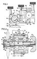
- Fig. 1 is a side elevational view showing the general arrangement of the mounting mechanism and the various clamping screws associated therewith, and showing in phantom outline a typical cutting wheel acting against a segment of a passing web; and
- Fig. 2 is an enlarged horizontal cross-sectional view, taken generally on line 2--2 in Fig. 1, showing details of the quick release rotary cutting wheel mounting mechanism provided by the invention.
- Slitting and/or perforating cutting wheels are described in U.S. Patent No. 4,177,730, and are well known. In general, a cross bar 10 (Fig. 1) is provided in a press or collator, extending across the web path which is indicated at W, passing over an anvil cylinder or
wheel 12. - The present invention relates to a novel quick-release mounting arrangement for a
cutting wheel 15, wherein theshaft 20 for supporting the wheel is a hollow shaft mounted withinbearings 22 that are contained in acylindrical housing 25. Ashoulder 26 on the shaft engages one bearing, and asnap ring 27 fitted toshaft 20 engages the other bearing, to confine the shaft in a lateral direction. Thehousing 25 in turn has anexternal thread 28 fitted into a suitable correspondingly threaded opening in a supportingarm 30.Arm 30 is pivotally mounted on apin 32 mounted in asplit support block 35, and held in position byset screw 36. The arm is spring-loaded in a direction to rotate the cutting wheel toward the passing web, by aspring 37 which acts betweenarm 30 and adisc 38 fitted to the end of apressure adjusting screw 40 threaded into theupper part 35b ofblock 35. Aset screw 42 in thearm 30 acts against thelower part 35a of the block to provide an adjustable lower limit to this spring action. Theblock 35 in turn is movably supported uponcross bar 10 which extends transversely of the passing web. - The end of the cutting
wheel support shaft 20 is provided with anexpandable collet hub 45, preferably a split collet arrangement, which is dimensioned to fit closely through the standardsized opening 47 in the center of thecutting wheel 15. The hub is fitted with aflange 48 against which the wheel is pressed as it is slipped over the collet hub, to locate the wheel precisely along its support shaft. - Within the hollow shaft there is a
mandrel 50 which is shiftable longitudinally within the hollow shaft, but has a close sliding fit with the shaft at thecentral region 51 to maintain concentricity of the shaft and mandrel. The mandrel has a tapered part 52 (preferably about 2° taper) that, when pressed within thecollet hub 45, urges the hub to expand evenly and lock inside the cutting wheel opening. At the other end ofmandrel 50, protruding from thehollow shaft 20, there is an operating handle orknob 55 attached to the mandrel by aset screw 56 and aspring 57 acts between the knob and the cylindrical housing, urging the mandrel in a direction to expand the collet hub 45 (to the right in Fig. 2). Thus, in its normal condition thehollow shaft 20, itscollet hub 45, and theinternal mandrel 50 are urged or biased to a condition where the cutting wheel is firmly held on its supporting shaft. - A
stop screw 60 with a largeflat head 61 is threaded into the collet hub end of the mandrel, and is locked into an adjusted position by aset screw 63. Thehead 61 abuts the end ofshaft 20 and thus limits the locking movement ofmandrel 50 to avoid over-tightening the collet hub to such an extent that it could not readily be released by thrusting onknob 55. - There is a latching member, preferably in the form of one or
more ball members 65 that protrude partially throughopenings 66 in the end of the hollow supporting shaft, outboard of the collet hub, on the opposite side of a mounted cutting wheel from the aforementioned locating flange. Interiorly of the shaft, this latching ball member rests against the mandrel head, inward ofstop screw head 61, to support the latching ball protruding somewhat through its corresponding opening and beyond the outer diameter of the end of the supporting shaft, as shown in Fig. 2. Therefore, in the normal position the latching ball member or members function as a retaining arrangement which will engage the hub of the cutting wheel before it reaches the end of its supporting shaft, should the wheel for some reason become loosened from its tight fit with the expanded collet hub. - To release a
cutting wheel 15, an operator merely presses longitudinally on theknob 55 to shift themandrel 50 against the force of thespring 57. This moves thetapered part 52 of the locking member at the opposite end of the mandrel longitudinally with respect to the collet hub and releases the force tending to expand the collet hub against theaperture 47 in thecutting wheel 15. At the same time, an undercutsection 68 at this end of the mandrel is moved into alignment with the latching ball member, so the ball can move inwardly as the cutting wheel is pulled off the supporting end of the hollow shaft, across the aperture through which the latching ball member normally projects. Therefore, a simple longitudinal thrust upon the knob, shifting the mandrel, will release the force which otherwise normally engages the collet hub against the central aperture of the cutting wheel, and also release the latching ball member. Thus a cutting wheel can be quickly dismounted or mounted, and either sharpened or replaced as may be desired. No tools are required to do this. - As previously mentioned, the
cylindrical housing 25 has a threaded exterior, thus when the housing is rotated within the threaded opening in the supportingarm 30, this provides for a lateral fine adjustment of the edge of a mounted cutting wheel. The range of this adjustment is indicated by the legend a in Fig. 2. - A retaining
ring 70, fitted in agroove 59 on the housing, prevents accidental withdrawal of the housing. At the other end of the housing aretainer sleeve 72 is fitted over thethreads 28 on the housing, and can be locked in place byset screws 73. A clamp screw 75 (Fig. 1) with a large knurled head extends across asplit 76 in the end of theblock 30, to hand tighten the threads once the housing is finally adjusted into position. Again, no tools are needed. -
Block 35 is comprised of two pieces, 35a and 35b, fastened together by a recessedcap screw 77, and aclamp screw 78, with a large knurled head, which can be loosened by hand to allow the block to slide alongbar 10 to a desired location. Thus, even the major adjusting movements of the block can be accomplished without need for tools. Thesmall block 80, attached to theupper block piece 35b, provides an anchor attachment (if desired) for a side register measuring device. - While the form of apparatus herein described constitutes a preferred embodiment of this invention, it is to be understood that the invention is not limited to this precise form of apparatus, and that changes may be made therein without departing from the scope of the invention, as defined in the appended claims.
Claims (6)
characterised in that
Applications Claiming Priority (2)
| Application Number | Priority Date | Filing Date | Title |
|---|---|---|---|
| US615846 | 1984-05-31 | ||
| US06/615,846 US4572047A (en) | 1984-05-31 | 1984-05-31 | Quick change slitter wheel holder |
Publications (2)
| Publication Number | Publication Date |
|---|---|
| EP0163402A1 EP0163402A1 (en) | 1985-12-04 |
| EP0163402B1 true EP0163402B1 (en) | 1988-08-10 |
Family
ID=24467046
Family Applications (1)
| Application Number | Title | Priority Date | Filing Date |
|---|---|---|---|
| EP85302711A Expired EP0163402B1 (en) | 1984-05-31 | 1985-04-17 | Quick change slitter wheel holder |
Country Status (4)
| Country | Link |
|---|---|
| US (1) | US4572047A (en) |
| EP (1) | EP0163402B1 (en) |
| CA (1) | CA1248011A (en) |
| DE (1) | DE3564213D1 (en) |
Families Citing this family (16)
| Publication number | Priority date | Publication date | Assignee | Title |
|---|---|---|---|---|
| US4781668A (en) * | 1986-10-30 | 1988-11-01 | Don Mowry Flexo, Inc. | Cutting device for a corrugated box machine |
| US4962684A (en) * | 1989-04-07 | 1990-10-16 | Mowry Donald E | Cutting device for a board machine |
| US5373766A (en) * | 1992-05-06 | 1994-12-20 | Monarch Machine Tool Co., Stamco Division | Slitter knife holder |
| EP0569767B1 (en) * | 1992-05-13 | 1996-01-03 | SCHOBER GmbH Werkzeug- und Maschinenbau | Knife support |
| US6109157A (en) * | 1999-06-09 | 2000-08-29 | S-B Power Tool Company | Arbor locking mechanism |
| US6382065B1 (en) * | 2000-04-13 | 2002-05-07 | Premark Feg L.L.C. | Removable pulley wheel arrangement and associated band saw apparatus |
| US20030188611A1 (en) * | 2002-04-04 | 2003-10-09 | Solberg Gary I. | Slitter Knife system |
| US20060174736A1 (en) * | 2005-02-10 | 2006-08-10 | Aaron Bloy | Slitter knife system and method |
| TW200904609A (en) * | 2007-07-26 | 2009-02-01 | Rexon Ind Corp Ltd | Quick-release structure for covering part of rotary sawing machine |
| EP2403685B1 (en) * | 2008-01-07 | 2015-05-06 | Lachlan George Reid | Attachment mechanism for a cutting disc |
| JP5735636B2 (en) * | 2010-05-04 | 2015-06-17 | ザ グリーソン ワークス | Tool to fix the tool to the spindle |
| GB2504486A (en) * | 2012-07-30 | 2014-02-05 | Meltech Eng | Continuous Extrusion Apparatus |
| DE102018124586A1 (en) * | 2018-10-05 | 2020-04-09 | DIENES WERKE FüR MASCHINENTEILE GMBH & CO. KG | Tubular bag machine and bag pack made with it |
| US12244127B2 (en) * | 2020-08-27 | 2025-03-04 | Te Connectivity Solutions Gmbh | Cutting arm for a cable preparation machine |
| JP7768718B2 (en) | 2021-10-05 | 2025-11-12 | 株式会社ディスコ | Cutting blade fixing mechanism |
| JP7776300B2 (en) * | 2021-10-05 | 2025-11-26 | 株式会社ディスコ | Cutting blade fixing mechanism |
Family Cites Families (21)
| Publication number | Priority date | Publication date | Assignee | Title |
|---|---|---|---|---|
| US1407145A (en) * | 1920-03-19 | 1922-02-21 | Gasteiner John | Internal chuck |
| US1465966A (en) * | 1920-08-25 | 1923-08-28 | Cameron Machine Co | Slitting means |
| US1944255A (en) * | 1931-08-17 | 1934-01-23 | Thurlow E Mcfall | Ring holding arbor |
| US2255885A (en) * | 1939-09-05 | 1941-09-16 | Charles J Steidl | Device for securing saws and other appliances to arbors |
| US2868548A (en) * | 1956-10-12 | 1959-01-13 | Milton L Lappin | Expanding sander chuck |
| US3173325A (en) * | 1963-01-09 | 1965-03-16 | Eastman Kodak Co | Expandable shaft for securing and positioning slitter knives |
| US3266535A (en) * | 1964-06-01 | 1966-08-16 | Singer Co | Safety blade clamping means for portable power saws |
| US3360276A (en) * | 1965-06-10 | 1967-12-26 | John J Peffer | Automatic screw machine tube stock extension means |
| US3501989A (en) * | 1968-01-18 | 1970-03-24 | Michael Lukaczyn Jr | Adjustable slitter holder |
| DE1808396A1 (en) * | 1968-11-12 | 1970-07-16 | Bosch Hausgeraete Gmbh | Household slicer |
| US3651728A (en) * | 1970-04-28 | 1972-03-28 | Dusenbery Co John | Cutting knife for slitting metal foil |
| US3727908A (en) * | 1970-08-17 | 1973-04-17 | Harris Intertype Corp | Continuous business forms |
| US3761008A (en) * | 1971-10-21 | 1973-09-25 | Detroit Sales Co | Expansion arbor |
| US3742714A (en) * | 1971-10-22 | 1973-07-03 | Koppers Co Inc | Pressure system for expanding shafts |
| US3831480A (en) * | 1972-05-01 | 1974-08-27 | J Phillips | Rotary cutter-slitter for high speed bursting apparatus |
| JPS4985684A (en) * | 1972-12-18 | 1974-08-16 | ||
| US3908499A (en) * | 1973-08-01 | 1975-09-30 | William Dale Reed | Knife retainer |
| US3905264A (en) * | 1974-08-30 | 1975-09-16 | Frank M Eddy | Slitting wheel holder |
| US4177730A (en) * | 1976-11-04 | 1979-12-11 | Harris Corporation | Method and apparatus for web printing |
| US4185526A (en) * | 1978-04-10 | 1980-01-29 | Intino Vito D | Holder for circular fabric cutter |
| IT1125595B (en) * | 1979-10-25 | 1986-05-14 | Elio Cavagna | CUTTER, OR SHEAR, FINDING USE IN PARTICULAR PAPER AND PLASTIC FILM PROCESSING, INCLUDING A CIRCULAR BLADE OR CIRCULAR KNIFE ANIMATED, DIRECTLY OR INDIRECTLY, BY AN ELECTRIC MOTOR OR OTHER |
-
1984
- 1984-05-31 US US06/615,846 patent/US4572047A/en not_active Expired - Lifetime
-
1985
- 1985-04-17 DE DE8585302711T patent/DE3564213D1/en not_active Expired
- 1985-04-17 EP EP85302711A patent/EP0163402B1/en not_active Expired
- 1985-05-30 CA CA000482785A patent/CA1248011A/en not_active Expired
Also Published As
| Publication number | Publication date |
|---|---|
| US4572047A (en) | 1986-02-25 |
| DE3564213D1 (en) | 1988-09-15 |
| EP0163402A1 (en) | 1985-12-04 |
| CA1248011A (en) | 1989-01-03 |
Similar Documents
| Publication | Publication Date | Title |
|---|---|---|
| US4572047A (en) | Quick change slitter wheel holder | |
| US5447086A (en) | Blade support | |
| US3945752A (en) | Cutting tool holder | |
| US5027684A (en) | Collar for mounting a split saw blade on an arbor | |
| EP0409973B1 (en) | Coupling for releasably fastening components parts to corresponding support parts | |
| US4936559A (en) | Indexing work-piece holder for numerically-controlled machine tools | |
| US3823892A (en) | Expandable roll core shaft unit | |
| US3871777A (en) | Clamping means for split rotary anvil and the like | |
| US3276101A (en) | Adjustable cutting tool | |
| US3905264A (en) | Slitting wheel holder | |
| US5507606A (en) | Back spotfacing tool | |
| US4541165A (en) | Automatic cutting edge changer for cutting tool | |
| US3877832A (en) | Locking means for adjustable boring bar inserts and the like | |
| US4203693A (en) | Duplicating machine for tubular keys | |
| EP0164549A1 (en) | Tool mounting device | |
| US2607989A (en) | Adjustable tracer finger | |
| US2546292A (en) | Cutting tool | |
| US3832925A (en) | Rotary print press including a device for punching rows of perforations in continuous paper webs | |
| US3309951A (en) | Machine tool turning head | |
| US5156352A (en) | Apparatus for winding narrow web strips on sleeves | |
| US3447403A (en) | Adjustable boring unit | |
| JPH0271996A (en) | Quick detachable device for tool | |
| US2567498A (en) | Centering device | |
| US6253652B1 (en) | Slitter blade locking device | |
| US5481945A (en) | Lock plate adjustment for geneva drive mechanism |
Legal Events
| Date | Code | Title | Description |
|---|---|---|---|
| PUAI | Public reference made under article 153(3) epc to a published international application that has entered the european phase |
Free format text: ORIGINAL CODE: 0009012 |
|
| AK | Designated contracting states |
Designated state(s): DE FR GB |
|
| 17P | Request for examination filed |
Effective date: 19860221 |
|
| 17Q | First examination report despatched |
Effective date: 19870416 |
|
| GRAA | (expected) grant |
Free format text: ORIGINAL CODE: 0009210 |
|
| AK | Designated contracting states |
Kind code of ref document: B1 Designated state(s): DE FR GB |
|
| REF | Corresponds to: |
Ref document number: 3564213 Country of ref document: DE Date of ref document: 19880915 |
|
| ET | Fr: translation filed | ||
| PLBE | No opposition filed within time limit |
Free format text: ORIGINAL CODE: 0009261 |
|
| STAA | Information on the status of an ep patent application or granted ep patent |
Free format text: STATUS: NO OPPOSITION FILED WITHIN TIME LIMIT |
|
| 26N | No opposition filed | ||
| REG | Reference to a national code |
Ref country code: FR Ref legal event code: TP |
|
| REG | Reference to a national code |
Ref country code: GB Ref legal event code: 732 |
|
| PGFP | Annual fee paid to national office [announced via postgrant information from national office to epo] |
Ref country code: DE Payment date: 19900403 Year of fee payment: 6 |
|
| PGFP | Annual fee paid to national office [announced via postgrant information from national office to epo] |
Ref country code: GB Payment date: 19900411 Year of fee payment: 6 |
|
| PGFP | Annual fee paid to national office [announced via postgrant information from national office to epo] |
Ref country code: FR Payment date: 19900421 Year of fee payment: 6 |
|
| PG25 | Lapsed in a contracting state [announced via postgrant information from national office to epo] |
Ref country code: GB Effective date: 19910417 |
|
| GBPC | Gb: european patent ceased through non-payment of renewal fee | ||
| PG25 | Lapsed in a contracting state [announced via postgrant information from national office to epo] |
Ref country code: FR Effective date: 19911230 |
|
| PG25 | Lapsed in a contracting state [announced via postgrant information from national office to epo] |
Ref country code: DE Effective date: 19920201 |
|
| REG | Reference to a national code |
Ref country code: FR Ref legal event code: ST |