EP0163391B1 - A thermoelectric generator for converting heat energy to electrical energy - Google Patents
A thermoelectric generator for converting heat energy to electrical energy Download PDFInfo
- Publication number
- EP0163391B1 EP0163391B1 EP85302387A EP85302387A EP0163391B1 EP 0163391 B1 EP0163391 B1 EP 0163391B1 EP 85302387 A EP85302387 A EP 85302387A EP 85302387 A EP85302387 A EP 85302387A EP 0163391 B1 EP0163391 B1 EP 0163391B1
- Authority
- EP
- European Patent Office
- Prior art keywords
- reaction zone
- alkali metal
- return line
- tube
- temperature
- Prior art date
- Legal status (The legal status is an assumption and is not a legal conclusion. Google has not performed a legal analysis and makes no representation as to the accuracy of the status listed.)
- Expired
Links
Images
Classifications
-
- H—ELECTRICITY
- H01—ELECTRIC ELEMENTS
- H01G—CAPACITORS; CAPACITORS, RECTIFIERS, DETECTORS, SWITCHING DEVICES OR LIGHT-SENSITIVE DEVICES, OF THE ELECTROLYTIC TYPE
- H01G9/00—Electrolytic capacitors, rectifiers, detectors, switching devices, light-sensitive or temperature-sensitive devices; Processes of their manufacture
- H01G9/21—Temperature-sensitive devices
-
- H—ELECTRICITY
- H01—ELECTRIC ELEMENTS
- H01M—PROCESSES OR MEANS, e.g. BATTERIES, FOR THE DIRECT CONVERSION OF CHEMICAL ENERGY INTO ELECTRICAL ENERGY
- H01M10/00—Secondary cells; Manufacture thereof
- H01M10/36—Accumulators not provided for in groups H01M10/05-H01M10/34
- H01M10/39—Accumulators not provided for in groups H01M10/05-H01M10/34 working at high temperature
- H01M10/3909—Sodium-sulfur cells
-
- H—ELECTRICITY
- H01—ELECTRIC ELEMENTS
- H01M—PROCESSES OR MEANS, e.g. BATTERIES, FOR THE DIRECT CONVERSION OF CHEMICAL ENERGY INTO ELECTRICAL ENERGY
- H01M14/00—Electrochemical current or voltage generators not provided for in groups H01M6/00 - H01M12/00; Manufacture thereof
-
- Y—GENERAL TAGGING OF NEW TECHNOLOGICAL DEVELOPMENTS; GENERAL TAGGING OF CROSS-SECTIONAL TECHNOLOGIES SPANNING OVER SEVERAL SECTIONS OF THE IPC; TECHNICAL SUBJECTS COVERED BY FORMER USPC CROSS-REFERENCE ART COLLECTIONS [XRACs] AND DIGESTS
- Y02—TECHNOLOGIES OR APPLICATIONS FOR MITIGATION OR ADAPTATION AGAINST CLIMATE CHANGE
- Y02E—REDUCTION OF GREENHOUSE GAS [GHG] EMISSIONS, RELATED TO ENERGY GENERATION, TRANSMISSION OR DISTRIBUTION
- Y02E60/00—Enabling technologies; Technologies with a potential or indirect contribution to GHG emissions mitigation
- Y02E60/10—Energy storage using batteries
Definitions
- thermoelectric generator devices which convert heat energy from a heat source directly to electrical energy by electrochemically expanding alkali metal, preferably sodium metal, across a solid electrolyte.
- thermoelectric generators to which the improvement of this invention applies and the principles of operation thereof have been described in U.S. patents Nos 3,458,356 and 4,094,877.
- "Sodium heat engine” is the name commonly given to such thermoelectric generators which electrochemically expand sodium metal across a solid electrolyte. While other alkali metals may be employed in the generator of this invention, the sodium heat engine is described herein as an example of such generators.
- the sodium heat engine generally comprises ( Figure 1) a closed container separated into a first and second reaction zone by a solid electrolyte. Liquid sodium metal is present in the first reaction zone (i.e., on one side of the solid electrolyte) and the first reaction zone is maintained during operation of the device at a pressure higher than that of the second reaction zone. In the lower pressure second reaction zone, a permeable, electrically conducting electrode is in contact with the solid electrolyte.
- a heat source raises the temperature of liquid sodium metal within the first reaction zone to a high temperature (T 2 ) and a corresponding high vapor pressure (P 2 ) which creates a sodium vapor pressure differential across the solid electrolyte.
- the elemental sodium gives up electrons to an electrode in contact with the sodium metal and the resulting sodium ions migrate through the solid electrolyte.
- the electrons having passed through an external load nuetralize sodium cations at the permeable electrode-solid electrolyte interface.
- Elemental sodium metal evaporates from the permeable electrode and migrates through the low pressure (P i ) second reaction zone (i.e., vacuum space) to a low temperature (T 1 ) condenser.
- the condensed liquid sodium may then be returned back to the higher temperature region within the first reaction zone, e.g. by means of a return line and an electromagnetic pump, to complete a closed cycle.
- sodium passes from the first reaction zone to the second and, where the device includes means for pumping the sodium back to the first reaction zone, the sodium completes the cycle.
- the process occurring in the electrolyte and at the sodium-electrolyte and electrode-electrolyte interfaces is nearly equivalent to an isothermal expansion of the alkali metal from pressure P 2 to P 1 at the temperature T 2 . No mechanical parts need move, and the work output of the process is electrical only.
- the sodium heat engine requires a return line to bring the condensed sodium from the second reaction zone to the interior of the first reaction zone.
- the sodium in the return line must be kept above its melting point to prevent plugging of the line.
- the temperature of the returning liquid sodium is sufficiently high to prevent the electrolyte from being thermally shocked by the sodium as it enters the hot first reaction zone.
- the return line has been brought to the first reaction zone by a route external to the condenser chamber as depicted in Figure 1 of this application or Figure 1 of U.S. Patent 4,098,958. Such routing has required special measures to ensure that the temperature of the sodium within the return line is properly maintained. Heating tapes, strapping of the tubing to the exterior of the condenser, etc., have been used for this purpose. By means of this invention, heat energy present within the second reaction zone can be efficiently employed for heating the returning liquid alkali metal.
- thermoelectric generator for converting heat energy from a heat source to electrical energy and which comprises:
- the temperature of the alkali metal introduced into the first reaction zone from the return line is at least sufficient to prevent thermal shock damage to the electrolyte.
- Locating the return line for the alkali metal as in this invention takes advantage of the high temperature thermal radiation passing between the electrolyte and the condenser. Still further it provides easy access for internally series-connecting electrolyte elements into larger system modules.
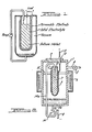
- the device of the invention may be described by referring to Figure 2 wherein one embodiment of the improved thermoelectric generator of this invention is shown in vertical cross section.
- the device is housed in a chemically resistant tube 1, e.g. stainless steel, ceramic, etc.
- a vacuum tight seal of tube 1 is provided by means comprising cover plate 9, which is made of stainless steel or other chemically resistant material, and thread, bolt or other conventional attaching means or sealing means such as gaskets, not shown.
- cover plate 9 Positioned inside tube 1 is a smaller tube 2 which comprises the solid electrolyte.
- Tube 2 is filled, partially or completely, with alkali metal 7, preferably, sodium.
- Tube 2 is sealed by enclosure means 10 made of chemically resistant material and is held in place within tube 1 by supports made of corrosion resistant electrically insulating material, e.g, aluminum oxide. Portions of the outer surface of electrolyte tube 2 are provided with a thin electrically conductive electrode 3 which is permeable enough to permit sodium to pass therethrough and sufficiently thick and continuous to conduct electricity. Electrode 3 is shown disproportionately thick in relation to other components to facilitate its location and identification.
- Tube 1 is provided with an outlet conduit 4 having a valve 5.
- a vacuum pump is connected to conduit 4 for reducing the pressure in tube 1.
- the device also is adapted to receive heat from a heat source.
- the thermoelectric generator is adapted to receive heat to maintain the temperature in tube 2 at least 100°C in excess of the lowest temperature in tube 1.
- a heater 6 is disposed about a portion of the side walls of tube 1.
- a heating device (not shown) disposed within a tube may be immersed in the alkali metal in tube 2.
- Other suitable means for heating are known to those skilled in the art.
- a negative lead 8 to an external circuit is connected to pump 13, a portion of the negative lead 8a being connected to the generator wall.
- a negative lead may comprise a chemically resistant metal wire extending into molten alkali metal 7 through cap 10, which wire may extend out of the generator through cover plate 9.
- Positive lead 11 to the external circuit passes through an electrically insulating feedthrough 12, which extends through cover plate 9, and is in electrical contact with electrode 3.
- tube 1 is evacuated by pumping means through conduit 4 to a pressure lower than about 13.3 Pa (0.1 Torr) preferably lower than about .133 Pa (0.001 Torr), and then sealed.
- Alkali metal, e.g., sodium, within tube 2 is heated to a temperature of 300°C or greater e.g., 300°C-1000°C, for example, by heating portions of the sides of the thermoelectric generator in a furnace, while another portion of the generator, (e.g., the lower end of tube 1) is maintained at least 100°C below that temperature by means such as thermal exchange with the ambient temperature air or other coolant fluids.
- alkali metal 7 passes through electrolyte 2 in the form of cations which then accept electrons from electrode 3 and return to the elemental state.
- the alkali metal in the bottom of the generator is returned to the first reaction zone in tube 2 by means comprising a return line 14.
- a portion 14a of the return line is located within the second reaction zone according to the improvement of this invention.
- Return line 14 enters the second reaction zone through the wall of tube 1, is hermetically sealed thereto, and extends through cap 10 into tube 2.
- An electromagnetic pump 13 is located in line 14to pump the sodium within the return line to tube 2.
- the preferred alkali metal reactant is sodium.
- potassium and other alkali metals can be used if the electrolyte separator is of compatible material.
- the solid electrolyte in the device of this invention may be glass, ceramic or polycrystalline ceramic material.
- ceramic materials which may be used for such devices and which demonstrate an unusually high resistance to attack by alkali metal are beta and beta-"alumina. Such materials are well known in the art and discussed in U.S. Patent 4,049,877.
- the electrode is permeable enough to permit the alkali metal vapors to pass therethrough but of sufficient thickness to conduct electricity. It may comprise, for example, a thin conducting layer of platinum bright paint comprising platinum chloride, or molybdenum films applied by sputtering or by such means as those described in U.S. Patent 4,049,877.
- the cell may include two or more electrolyte elements connected in series and/or two or more return lines located within the generator according to this invention.
- the improvement of this invention comprises that at least a portion of the return line is located within the second reaction zone whereby the portion of the return line within the second reaction zone receives sufficient heat from the heat source during operation of the generator to maintain the alkali metal within that portion of return line at a temperature above the melting point of the alkali metal.
- the temperature of the alkali metal introduced into the first reaction zone is at least sufficient to prevent thermal shock damage to the electrolyte.
- Locating a portion of the return line within the second reaction zone offers distinct advantages described above as compared to prior art devices wherein the return line is routed external to the generator, as shown in Figure 1.
- this return line can be constructed of small diameter tubing. Tubing 0.16 to 0.32 cm (1/16th to 1/8th inch) diameter is adequate for a cell employing, e.g., sodium and delivering a few hundred amperes.
- the return line may be composed of any material which is resistant to corrosion by the alkali metal employed in the generator. While return lines made of ceramic materials may be employed, it is preferable to employ return lines made of metal since metal return lines are available in small diameter and have flexibility and durability. While Figure 2 indicates an embodiment of this invention wherein the liquid alkali metal is preferably returned to the upper end of the first reaction zone, the return line may enter the first reaction zone at any point, e.g., at the bottom.
- the return line may enter the first reaction zone at the upper end since introduction of the liquid alkali metal into the upper end of this zone is aided by gravity.
- the return line 14 preferably enters the generator through the lower generator wall near the pumping means 13, the return line may enter the generator through, e.g., the side walls. Additionally, the return line may enter and exit the generator 1 if desired.
- the temperature of the sodium metal in the return line must be above the melting point of the sodium metal and preferably is above that which would result in thermal shock to the ceramic electrolyte. To prevent thermal shock damage to beta and beta-"alumina electrolytes, the temperature of alkali metal entering the first reaction zone should be within 200°C of this zone and more preferably within about 100°C of that of this zone.
- the return line is located within the second reaction zone so as to receive heat from the heat source, e.g., either directly by thermal radiation or by thermal conduction from the heat source, or by reflected thermal radiation within the second reaction zone.
- the heat source comprises a heater disposed around a portion of tube 1 as in Figure 2 (i.e., wherein a portion of the side walls of tube 1 are hot)
- the return line can parallel the length of the tube 1 and contact tube 1 or be located parallel to the tube in the vacuum space between the tube 1 and tube 2.
- Immersion heaters can also be employed in tube 2 to provide heat energy for the device.
- the immersion heaters can be closed- ended heat pipes within tube 2 as described in U.S. Patent 4,098,958.
- the return line is preferably located near or in thermal contact with electrolyte 2. If the cell contains a central heating tube extending the length of the cell, electrolyte tube enclosed first reaction zones could be parallel arranged around such a central heating tube. The wall of tube 1 would then be relatively cool. The return lines, in this instance, would be advantageously located between the central heater tube and the electrolyte tubes. Selection of the optimal location of the return line within the second reaction zone and the optimal location of its entry into the first reaction zone according to this invention will depend, e.g. on the temperature to which it is desired to heat the returning liquid and the location of the heat source and the first reaction zone.
- a sodium heat engine cell was constructed generally in accordance with Figure 2 with 2 beta- "alumina electrolyte tubes arranged for series connection within the chamber formed by tube 1.
- heat was supplied from a central heater tube disposed centrally in the chamber.
- the heater tube was maintained at a temperature of approximately 700°C and the condenser surface comprised the outer wall of tube 1 and was maintained at a temperature of approximately 200°C.
- the two electrolyte tubes were fed with sodium at the top end, using returning lines comprising inconel tubes of 0.8 cm (0.032 inch) inside diameter and 0.16 cm (0.063 inch) outside diameter which were connected at their lower ends to a single, small chamber fed from an electromagnetic pump as described previously and shown (pump 13) in Fig. 2.
- the electrolyte tubes were approximately 30 cm in length and the return lines approximately 40 cm to provide room for assembly.
- the return lines were placed between the two electrolyte tubes and thus were fully exposed to the thermal radiation from the central heater wall surface. No additional heating was provided to the return lines. It was found that the sodium flow through these narrow lines was quite capable of supporting the maximum net device current of 50 amperes, corresponding to a total sodium flow of approximately 100 cm 3 /hr.
- Asodium heat engine cell was constructed in the end-condensed geometry shown in Figure 2 using a single beta"-alumina electrolyte tube of 1.6 cm outer diameter and approximately 1.2 mm wall thickness.
- the sides of tube 1 were maintained at a temperature of 800-900°C by immersion in a furnace.
- the sodium feed line constructed of the same material used for the feed lines in Example 1 was brought through the bottom of the chamber from an electromagnetic pump and routed partially along the inner surface of the outside wall to the upper end of the electrolyte tube.
- the condenser surface comprises the surface of liquid sodium collected in the bottom end of the cell. This surface was maintained at a temperature of approximately 220°C thereby establishing the temperature and vapor pressure differential required for operation of the device.
- the sodium return lines can be efficiently coupled thermally to the heated surface and thus accomplish the preheating of the incoming sodium to a temperature sufficiently close to the sodium in the hot zone within the electrolyte tube so that inadvertant thermal shock problems due to admission of cold sodium are avoided.
Description
- This invention relates to improved thermoelectric generator devices which convert heat energy from a heat source directly to electrical energy by electrochemically expanding alkali metal, preferably sodium metal, across a solid electrolyte.
- Thermoelectric generators to which the improvement of this invention applies and the principles of operation thereof have been described in U.S. patents Nos 3,458,356 and 4,094,877. "Sodium heat engine" is the name commonly given to such thermoelectric generators which electrochemically expand sodium metal across a solid electrolyte. While other alkali metals may be employed in the generator of this invention, the sodium heat engine is described herein as an example of such generators.
- The sodium heat engine generally comprises (Figure 1) a closed container separated into a first and second reaction zone by a solid electrolyte. Liquid sodium metal is present in the first reaction zone (i.e., on one side of the solid electrolyte) and the first reaction zone is maintained during operation of the device at a pressure higher than that of the second reaction zone. In the lower pressure second reaction zone, a permeable, electrically conducting electrode is in contact with the solid electrolyte. During operation of such a device, a heat source raises the temperature of liquid sodium metal within the first reaction zone to a high temperature (T2) and a corresponding high vapor pressure (P2) which creates a sodium vapor pressure differential across the solid electrolyte. In response to this pressure differential, the elemental sodium gives up electrons to an electrode in contact with the sodium metal and the resulting sodium ions migrate through the solid electrolyte. The electrons having passed through an external load, nuetralize sodium cations at the permeable electrode-solid electrolyte interface. Elemental sodium metal evaporates from the permeable electrode and migrates through the low pressure (Pi) second reaction zone (i.e., vacuum space) to a low temperature (T1) condenser. The condensed liquid sodium may then be returned back to the higher temperature region within the first reaction zone, e.g. by means of a return line and an electromagnetic pump, to complete a closed cycle. Thus, during operation of the device, sodium passes from the first reaction zone to the second and, where the device includes means for pumping the sodium back to the first reaction zone, the sodium completes the cycle. The process occurring in the electrolyte and at the sodium-electrolyte and electrode-electrolyte interfaces is nearly equivalent to an isothermal expansion of the alkali metal from pressure P2 to P1 at the temperature T2. No mechanical parts need move, and the work output of the process is electrical only.
- In continuous operation, the sodium heat engine requires a return line to bring the condensed sodium from the second reaction zone to the interior of the first reaction zone. The sodium in the return line must be kept above its melting point to prevent plugging of the line. Preferably, the temperature of the returning liquid sodium is sufficiently high to prevent the electrolyte from being thermally shocked by the sodium as it enters the hot first reaction zone. In previous designs, the return line has been brought to the first reaction zone by a route external to the condenser chamber as depicted in Figure 1 of this application or Figure 1 of U.S. Patent 4,098,958. Such routing has required special measures to ensure that the temperature of the sodium within the return line is properly maintained. Heating tapes, strapping of the tubing to the exterior of the condenser, etc., have been used for this purpose. By means of this invention, heat energy present within the second reaction zone can be efficiently employed for heating the returning liquid alkali metal.
- According to the invention there is provided a thermoelectric generator for converting heat energy from a heat source to electrical energy and which comprises:
- (i) means (2, 10) for enclosing a first reaction zone, which are located within means (1, 9) for enclosing a second reaction zone, and which include;
- a reaction zone separator (2) which;
- (a) separates and substantially completes enclosure of said first reaction zone and said second reaction zone, and
- (b) comprises a cationically conductive, solid electrolyte that is essentially impermeable to elemental alkali metal and compounds thereof and ionically conductive with respect to cations of said alkali metals;
- a reaction zone separator (2) which;
- (ii) elemental alkali metal (7) within said first reaction zone and in fluid communication with said solid electrolyte;
- (iii) an electrode (3) within said second reaction zone in electrical contact with said solid electrolyte and sufficiently permeable to permit alkali metal to pass therethrough;
- (iv) means (6) for maintaining a temperature in said first reaction zone at least 100°C in excess of the lowest temperature in said second reaction zone; and
- (v) means (13, 14) for returning condensed elemental alkali metal from said second reaction zone to said first reaction zone, which means comprise a return line (14) for said condensed alkali metal and a means (13) for pumping said condensed alkali metal through said return line;
- Preferably, the temperature of the alkali metal introduced into the first reaction zone from the return line is at least sufficient to prevent thermal shock damage to the electrolyte.
- By locating the alkali metal return line in the vacuum space within the generator, returning alkali metal may be efficiently heated to each substantially the temperature of the hot, first reaction zone prior to its introduction therein. Thus, the device is protected against the inadvertent introduction of cold alkali metal into the first reaction zone, where contact of cold alkali metal with the heated electrolyte would lead t thermal shock damage to the electrolyte. Locating the return line for the alkali metal as in this invention takes advantage of the high temperature thermal radiation passing between the electrolyte and the condenser. Still further it provides easy access for internally series-connecting electrolyte elements into larger system modules.
- The invention will now be described by way of example, with reference to the accompanying drawings in which:
- Figure 1 is a schematic diagram of a thermoelectric generator to which the improvement of this invention applies. In such conventional cell, the alkali metal return line is located outside the cell.
- Figure 2 is a vertical cross sectional view of one embodiment of the improved thermoelectric generator of this invention.
- Thermoelectric generator to which the improvement of this invention applies are disclosed above generally in US Patent, 3,458,356.
- The device of the invention may be described by referring to Figure 2 wherein one embodiment of the improved thermoelectric generator of this invention is shown in vertical cross section. The device is housed in a chemically
resistant tube 1, e.g. stainless steel, ceramic, etc. A vacuum tight seal oftube 1 is provided by means comprising cover plate 9, which is made of stainless steel or other chemically resistant material, and thread, bolt or other conventional attaching means or sealing means such as gaskets, not shown. Positioned insidetube 1 is asmaller tube 2 which comprises the solid electrolyte.Tube 2 is filled, partially or completely, with alkali metal 7, preferably, sodium.Tube 2 is sealed by enclosure means 10 made of chemically resistant material and is held in place withintube 1 by supports made of corrosion resistant electrically insulating material, e.g, aluminum oxide. Portions of the outer surface ofelectrolyte tube 2 are provided with a thin electrically conductive electrode 3 which is permeable enough to permit sodium to pass therethrough and sufficiently thick and continuous to conduct electricity. Electrode 3 is shown disproportionately thick in relation to other components to facilitate its location and identification. Tube 1 is provided with an outlet conduit 4 having a valve 5. A vacuum pump, not shown, is connected to conduit 4 for reducing the pressure intube 1. - The device also is adapted to receive heat from a heat source. Specifically, the thermoelectric generator is adapted to receive heat to maintain the temperature in
tube 2 at least 100°C in excess of the lowest temperature intube 1. In the device shown in Figure 2, a heater 6 is disposed about a portion of the side walls oftube 1. Alternatively, a heating device (not shown) disposed within a tube may be immersed in the alkali metal intube 2. Other suitable means for heating are known to those skilled in the art. - Wherein it is desired that the return line act as part of the means for conducting electron flow between the elemental alkali metal in
tube 2 and electrode 3, the return line contacts alkali metal 7 withintube 2. A negative lead 8 to an external circuit, not shown, is connected to pump 13, a portion of the negative lead 8a being connected to the generator wall. Alternately, a negative lead (not shown) may comprise a chemically resistant metal wire extending into molten alkali metal 7 through cap 10, which wire may extend out of the generator through cover plate 9. Positive lead 11 to the external circuit passes through an electricallyinsulating feedthrough 12, which extends through cover plate 9, and is in electrical contact with electrode 3. - In operation of the device,
tube 1 is evacuated by pumping means through conduit 4 to a pressure lower than about 13.3 Pa (0.1 Torr) preferably lower than about .133 Pa (0.001 Torr), and then sealed. Alkali metal, e.g., sodium, withintube 2 is heated to a temperature of 300°C or greater e.g., 300°C-1000°C, for example, by heating portions of the sides of the thermoelectric generator in a furnace, while another portion of the generator, (e.g., the lower end of tube 1) is maintained at least 100°C below that temperature by means such as thermal exchange with the ambient temperature air or other coolant fluids. A difference in alkali metal vapor pressure on the two sides of the electrolyte results in the creation of difference of electrical potential across the electrolyte. As electrons flow through the external circuit, alkali metal 7 passes throughelectrolyte 2 in the form of cations which then accept electrons from electrode 3 and return to the elemental state. - If the lower part of
tube 1 is maintained at sufficiently low temperature, the alkali metal condenses there and pressure- inouter tube 1 becomes the vapor pressure of the alkali metal modified by any vapor pressure drop produced by the mass flow of the alkali metal from electrode 3 to the cooler walls oftube 1. In continuous operation, the condensed alkali metal in the bottom of the generator is returned to the first reaction zone intube 2 by means comprising a return line 14. A portion 14a of the return line is located within the second reaction zone according to the improvement of this invention. Return line 14 enters the second reaction zone through the wall oftube 1, is hermetically sealed thereto, and extends through cap 10 intotube 2. An electromagnetic pump 13 is located in line 14to pump the sodium within the return line totube 2. - The preferred alkali metal reactant is sodium. However, potassium and other alkali metals can be used if the electrolyte separator is of compatible material. The solid electrolyte in the device of this invention may be glass, ceramic or polycrystalline ceramic material. Among the ceramic materials which may be used for such devices and which demonstrate an unusually high resistance to attack by alkali metal are beta and beta-"alumina. Such materials are well known in the art and discussed in U.S. Patent 4,049,877.
- The electrode is permeable enough to permit the alkali metal vapors to pass therethrough but of sufficient thickness to conduct electricity. It may comprise, for example, a thin conducting layer of platinum bright paint comprising platinum chloride, or molybdenum films applied by sputtering or by such means as those described in U.S. Patent 4,049,877.
- While Figure 2 illustrates one embodiment of the improvement of this invention, other embodiments are likewise useful. For example, the cell may include two or more electrolyte elements connected in series and/or two or more return lines located within the generator according to this invention.
- The improvement of this invention comprises that at least a portion of the return line is located within the second reaction zone whereby the portion of the return line within the second reaction zone receives sufficient heat from the heat source during operation of the generator to maintain the alkali metal within that portion of return line at a temperature above the melting point of the alkali metal. Preferably, the temperature of the alkali metal introduced into the first reaction zone is at least sufficient to prevent thermal shock damage to the electrolyte.
- Locating a portion of the return line within the second reaction zone offers distinct advantages described above as compared to prior art devices wherein the return line is routed external to the generator, as shown in Figure 1.
- Because of low alkali metal flow rates, this return line can be constructed of small diameter tubing. Tubing 0.16 to 0.32 cm (1/16th to 1/8th inch) diameter is adequate for a cell employing, e.g., sodium and delivering a few hundred amperes. The return line may be composed of any material which is resistant to corrosion by the alkali metal employed in the generator. While return lines made of ceramic materials may be employed, it is preferable to employ return lines made of metal since metal return lines are available in small diameter and have flexibility and durability. While Figure 2 indicates an embodiment of this invention wherein the liquid alkali metal is preferably returned to the upper end of the first reaction zone, the return line may enter the first reaction zone at any point, e.g., at the bottom. However, it is preferable to have the return line enter the first reaction zone at the upper end since introduction of the liquid alkali metal into the upper end of this zone is aided by gravity. While in this embodiment the return line 14 preferably enters the generator through the lower generator wall near the pumping means 13, the return line may enter the generator through, e.g., the side walls. Additionally, the return line may enter and exit the
generator 1 if desired. - While it is preferable to heat the returning alkali metal to a temperature nearly that of the first reaction zone, it is not necessary to do so. The temperature of the sodium metal in the return line must be above the melting point of the sodium metal and preferably is above that which would result in thermal shock to the ceramic electrolyte. To prevent thermal shock damage to beta and beta-"alumina electrolytes, the temperature of alkali metal entering the first reaction zone should be within 200°C of this zone and more preferably within about 100°C of that of this zone. The return line is located within the second reaction zone so as to receive heat from the heat source, e.g., either directly by thermal radiation or by thermal conduction from the heat source, or by reflected thermal radiation within the second reaction zone. If the heat source comprises a heater disposed around a portion of
tube 1 as in Figure 2 (i.e., wherein a portion of the side walls oftube 1 are hot) the return line can parallel the length of thetube 1 andcontact tube 1 or be located parallel to the tube in the vacuum space between thetube 1 andtube 2. Immersion heaters can also be employed intube 2 to provide heat energy for the device. The immersion heaters can be closed- ended heat pipes withintube 2 as described in U.S. Patent 4,098,958. - In the immersion heater method of heating, the return line is preferably located near or in thermal contact with
electrolyte 2. If the cell contains a central heating tube extending the length of the cell, electrolyte tube enclosed first reaction zones could be parallel arranged around such a central heating tube. The wall oftube 1 would then be relatively cool. The return lines, in this instance, would be advantageously located between the central heater tube and the electrolyte tubes. Selection of the optimal location of the return line within the second reaction zone and the optimal location of its entry into the first reaction zone according to this invention will depend, e.g. on the temperature to which it is desired to heat the returning liquid and the location of the heat source and the first reaction zone. - The invention will be further understood by referring to the following detailed examples. It should be understood that the specific examples are presented by way of illustration and not by way of limitation.
- A sodium heat engine cell was constructed generally in accordance with Figure 2 with 2 beta- "alumina electrolyte tubes arranged for series connection within the chamber formed by
tube 1. In this example, heat was supplied from a central heater tube disposed centrally in the chamber. The heater tube was maintained at a temperature of approximately 700°C and the condenser surface comprised the outer wall oftube 1 and was maintained at a temperature of approximately 200°C. The two electrolyte tubes were fed with sodium at the top end, using returning lines comprising inconel tubes of 0.8 cm (0.032 inch) inside diameter and 0.16 cm (0.063 inch) outside diameter which were connected at their lower ends to a single, small chamber fed from an electromagnetic pump as described previously and shown (pump 13) in Fig. 2. The electrolyte tubes were approximately 30 cm in length and the return lines approximately 40 cm to provide room for assembly. The return lines were placed between the two electrolyte tubes and thus were fully exposed to the thermal radiation from the central heater wall surface. No additional heating was provided to the return lines. It was found that the sodium flow through these narrow lines was quite capable of supporting the maximum net device current of 50 amperes, corresponding to a total sodium flow of approximately 100 cm3/hr. - Asodium heat engine cell was constructed in the end-condensed geometry shown in Figure 2 using a single beta"-alumina electrolyte tube of 1.6 cm outer diameter and approximately 1.2 mm wall thickness. The sides of
tube 1 were maintained at a temperature of 800-900°C by immersion in a furnace. The sodium feed line constructed of the same material used for the feed lines in Example 1 was brought through the bottom of the chamber from an electromagnetic pump and routed partially along the inner surface of the outside wall to the upper end of the electrolyte tube. The condenser surface comprises the surface of liquid sodium collected in the bottom end of the cell. This surface was maintained at a temperature of approximately 220°C thereby establishing the temperature and vapor pressure differential required for operation of the device. In this cell, operating at higher temperatures than the cell in Example 1, the sodium return lines can be efficiently coupled thermally to the heated surface and thus accomplish the preheating of the incoming sodium to a temperature sufficiently close to the sodium in the hot zone within the electrolyte tube so that inadvertant thermal shock problems due to admission of cold sodium are avoided.
wherein at least a portion (14)a of said return line (14) is located within said second reaction zone, characterised in that said portion (14a) of said return line (14) is so located that it receives sufficient heat from the heat source during operation of said generator to maintain said alkali metal within said portion of said return line at a temperature above the melting point of said alkali metal.
Claims (6)
wherein at least a portion (14a) of said return line (14) is located within said second reaction zone, characterised in that said portion (14a) of said return line (14) is so located that it receives sufficient heat from the heat source during operation of said generator to maintain said alkali metal within said portion of said return line at a temperature above the melting point of said alkali metal.
Applications Claiming Priority (2)
| Application Number | Priority Date | Filing Date | Title |
|---|---|---|---|
| US06/614,421 US4510210A (en) | 1984-05-25 | 1984-05-25 | Internal-integral sodium return line for sodium heat engine |
| US614421 | 1984-05-25 |
Publications (3)
| Publication Number | Publication Date |
|---|---|
| EP0163391A2 EP0163391A2 (en) | 1985-12-04 |
| EP0163391A3 EP0163391A3 (en) | 1986-03-19 |
| EP0163391B1 true EP0163391B1 (en) | 1989-01-18 |
Family
ID=24461195
Family Applications (1)
| Application Number | Title | Priority Date | Filing Date |
|---|---|---|---|
| EP85302387A Expired EP0163391B1 (en) | 1984-05-25 | 1985-04-04 | A thermoelectric generator for converting heat energy to electrical energy |
Country Status (5)
| Country | Link |
|---|---|
| US (1) | US4510210A (en) |
| EP (1) | EP0163391B1 (en) |
| JP (1) | JPS60249879A (en) |
| CA (1) | CA1241368A (en) |
| DE (1) | DE3567774D1 (en) |
Families Citing this family (45)
| Publication number | Priority date | Publication date | Assignee | Title |
|---|---|---|---|---|
| US4714798A (en) * | 1985-12-24 | 1987-12-22 | Ford Motor Company | Titanium nitride electrodes for thermoelectric generators |
| US4686320A (en) * | 1985-12-27 | 1987-08-11 | Ford Motor Company | Electronically and ionically conducting electrodes for thermoelectric generators |
| US4871626A (en) * | 1987-08-06 | 1989-10-03 | California Institute Of Technology | Current collector for AMTEC |
| US4847171A (en) * | 1988-03-10 | 1989-07-11 | Ford Motor Company | Molybdenum oxide electrodes for thermoelectric generators |
| US4868072A (en) * | 1988-07-28 | 1989-09-19 | The United States Of America As Represented By The United States Department Of Energy | Liquid metal thermal electric converter |
| US4857421A (en) * | 1988-11-14 | 1989-08-15 | Thermacore, Inc. | Alkali metal thermoelectric genreator |
| US4965142A (en) * | 1989-06-01 | 1990-10-23 | Ford Motor Company | Molybdenum-platinum-oxide electrodes for thermoelectric generators |
| US4948679A (en) * | 1989-06-01 | 1990-08-14 | Ford Motor Company | Microscreen radiation shield for thermoelectric generator |
| US5042847A (en) * | 1989-07-20 | 1991-08-27 | Ford Motor Company | Metal to ceramic sealed joint |
| DE4016930C2 (en) * | 1990-05-25 | 1994-03-03 | Kernforschungsz Karlsruhe | Thermoelectric converter based on the AMTEC principle |
| US5066337A (en) * | 1990-08-16 | 1991-11-19 | The United States Of America As Represented By The Administrator Of The National Aeronautics And Space Administration | Thermal power transfer system using applied potential difference to sustain operating pressure difference |
| US5089054A (en) * | 1990-11-28 | 1992-02-18 | Westinghouse Electric Corp. | Flat plate alkali metal thermoelectric converter module |
| US5441575A (en) * | 1993-01-11 | 1995-08-15 | The United States Of America As Represented By The United States National Aeronautics And Space Administration | AMTEC vapor-vapor series connected cells |
| US5928436A (en) * | 1997-02-26 | 1999-07-27 | Advanced Modular Power Systems, Inc. | Means for controlling thermal properties of AMTEC cells |
| US5939666A (en) * | 1997-06-17 | 1999-08-17 | Hitachi Maxell, Ltd. | Evaporation front position control in alkali metal thermal electric conversion (AMTEC) cells |
| JP2010198788A (en) * | 2009-02-23 | 2010-09-09 | Tohoku Univ | Liquid sodium battery |
| US8742814B2 (en) | 2009-07-15 | 2014-06-03 | Yehuda Binder | Sequentially operated modules |
| US8602833B2 (en) | 2009-08-06 | 2013-12-10 | May Patents Ltd. | Puzzle with conductive path |
| US8378208B1 (en) | 2009-08-07 | 2013-02-19 | The Boeing Company | AMTEC power system with thermal block |
| US8648245B1 (en) | 2009-08-07 | 2014-02-11 | The Boeing Company | AMTEC power system with thermal block |
| US8281783B2 (en) * | 2009-08-07 | 2012-10-09 | The Boeing Company | Thermal absorber with gravity counterflow regeneration for solar AMTEC power systems |
| US8629345B1 (en) | 2009-08-26 | 2014-01-14 | The Boeing Company | Solar AMTEC power system |
| US8575468B2 (en) * | 2009-08-26 | 2013-11-05 | The Boeing Company | Solar AMTEC power system |
| US8344237B1 (en) | 2009-10-27 | 2013-01-01 | The Boeing Company | AMTEC power system |
| US11330714B2 (en) | 2011-08-26 | 2022-05-10 | Sphero, Inc. | Modular electronic building systems with magnetic interconnections and methods of using the same |
| US9019718B2 (en) | 2011-08-26 | 2015-04-28 | Littlebits Electronics Inc. | Modular electronic building systems with magnetic interconnections and methods of using the same |
| US9597607B2 (en) | 2011-08-26 | 2017-03-21 | Littlebits Electronics Inc. | Modular electronic building systems with magnetic interconnections and methods of using the same |
| CN104854726B (en) | 2012-10-16 | 2018-09-21 | 安布里公司 | Electrochemical energy storage device and shell |
| US11211641B2 (en) | 2012-10-18 | 2021-12-28 | Ambri Inc. | Electrochemical energy storage devices |
| US10541451B2 (en) | 2012-10-18 | 2020-01-21 | Ambri Inc. | Electrochemical energy storage devices |
| US9520618B2 (en) | 2013-02-12 | 2016-12-13 | Ambri Inc. | Electrochemical energy storage devices |
| US11387497B2 (en) | 2012-10-18 | 2022-07-12 | Ambri Inc. | Electrochemical energy storage devices |
| US9312522B2 (en) | 2012-10-18 | 2016-04-12 | Ambri Inc. | Electrochemical energy storage devices |
| US9735450B2 (en) | 2012-10-18 | 2017-08-15 | Ambri Inc. | Electrochemical energy storage devices |
| US11721841B2 (en) | 2012-10-18 | 2023-08-08 | Ambri Inc. | Electrochemical energy storage devices |
| US10270139B1 (en) | 2013-03-14 | 2019-04-23 | Ambri Inc. | Systems and methods for recycling electrochemical energy storage devices |
| US9502737B2 (en) | 2013-05-23 | 2016-11-22 | Ambri Inc. | Voltage-enhanced energy storage devices |
| DK3058605T3 (en) | 2013-10-16 | 2024-03-04 | Ambri Inc | SEALS FOR DEVICES OF REACTIVE HIGH TEMPERATURE MATERIAL |
| EP3122705A4 (en) * | 2014-03-28 | 2018-03-28 | Mako, Jr., Frederick M. | Method for joining ceramics to ceramics or ceramics to metals, and apparatus |
| US10181800B1 (en) | 2015-03-02 | 2019-01-15 | Ambri Inc. | Power conversion systems for energy storage devices |
| WO2016141354A2 (en) | 2015-03-05 | 2016-09-09 | Ambri Inc. | Ceramic materials and seals for high temperature reactive material devices |
| US9893385B1 (en) | 2015-04-23 | 2018-02-13 | Ambri Inc. | Battery management systems for energy storage devices |
| US11929466B2 (en) | 2016-09-07 | 2024-03-12 | Ambri Inc. | Electrochemical energy storage devices |
| JP7201613B2 (en) | 2017-04-07 | 2023-01-10 | アンブリ・インコーポレイテッド | Molten salt battery with solid metal cathode |
| US11616844B2 (en) | 2019-03-14 | 2023-03-28 | Sphero, Inc. | Modular electronic and digital building systems and methods of using the same |
Family Cites Families (8)
| Publication number | Priority date | Publication date | Assignee | Title |
|---|---|---|---|---|
| US687121A (en) * | 1901-04-17 | 1901-11-19 | James J Callender | Electric battery. |
| US1379854A (en) * | 1918-09-04 | 1921-05-31 | Dinin Alfred | Liquid-tight joint for preventing leakage between the terminal rods and covers of electric accumulators |
| NL261579A (en) * | 1960-02-23 | |||
| US3458356A (en) * | 1966-05-02 | 1969-07-29 | Ford Motor Co | Thermo-electric generator |
| US3522101A (en) * | 1968-01-10 | 1970-07-28 | Inst Gas Technology | Power module including thermally regenerative battery and fuel cell and method of operation |
| US4049877A (en) * | 1975-09-17 | 1977-09-20 | Ford Motor Company | Thermoelectric generator |
| US4098958A (en) * | 1977-07-07 | 1978-07-04 | Ford Motor Company | Thermoelectric generator devices and methods |
| DE3040394A1 (en) * | 1980-10-25 | 1982-07-08 | Varta Batterie Ag, 3000 Hannover | ELECTROCHEMICAL SECONDARY CELL |
-
1984
- 1984-05-25 US US06/614,421 patent/US4510210A/en not_active Expired - Lifetime
-
1985
- 1985-03-15 CA CA000476707A patent/CA1241368A/en not_active Expired
- 1985-04-04 EP EP85302387A patent/EP0163391B1/en not_active Expired
- 1985-04-04 DE DE8585302387T patent/DE3567774D1/en not_active Expired
- 1985-04-22 JP JP60084689A patent/JPS60249879A/en active Granted
Also Published As
| Publication number | Publication date |
|---|---|
| DE3567774D1 (en) | 1989-02-23 |
| JPH0515158B2 (en) | 1993-02-26 |
| JPS60249879A (en) | 1985-12-10 |
| US4510210A (en) | 1985-04-09 |
| CA1241368A (en) | 1988-08-30 |
| EP0163391A3 (en) | 1986-03-19 |
| EP0163391A2 (en) | 1985-12-04 |
Similar Documents
| Publication | Publication Date | Title |
|---|---|---|
| EP0163391B1 (en) | A thermoelectric generator for converting heat energy to electrical energy | |
| US4098958A (en) | Thermoelectric generator devices and methods | |
| US4505991A (en) | Sodium heat engine electrical feedthrough | |
| US5013612A (en) | Braze material for joining ceramic to metal and ceramic to ceramic surfaces and joined ceramic to metal and ceramic to ceramic article | |
| US4383013A (en) | High temperature multicell electrochemical storage batteries | |
| US4042757A (en) | Thermo-electric generators | |
| US4049877A (en) | Thermoelectric generator | |
| CA1133577A (en) | Internal geometry of alkali metal thermoelectric generator devices | |
| CA2017256C (en) | Metal to ceramic sealed joint | |
| US4310607A (en) | Battery cell construction | |
| US4049889A (en) | Hermetically sealed alkali metal battery container | |
| EP0044753B1 (en) | Electrochemical storage batteries and modules therefor | |
| US5998728A (en) | Ionically insulating seal for alkali metal thermal to electric conversion (AMTEC) cells | |
| US4084040A (en) | Cell casing and a hermetically sealed sodium-sulfur cell | |
| US4868072A (en) | Liquid metal thermal electric converter | |
| US3976503A (en) | Process for recharging secondary batteries | |
| GB2081000A (en) | Controlling the temperature of e.g. sodium-sulphur batteries | |
| EP0400807B1 (en) | Microscreen radiaton shield for thermoelectric generator and generator with such a shield | |
| El Genk et al. | Recent advances in vapor-anode, multi-tube, alkali metal thermal-to-electric conversion cells for space power | |
| Choudhury | Thermochemical Stability of β‐and β ″‐Alumina Electrolytes in Na/S Cells: I. The Activities of and | |
| Weber | Sodium heat engine electrical feedthrough | |
| GB2140608A (en) | Energy conversion devices using liquid sodium and beta alumina ceramic electrolyte material | |
| US20020079214A1 (en) | Apparatus and system for refining sodium | |
| JP2887253B1 (en) | Thermoelectric conversion generator | |
| GB1586659A (en) | Electrochemical cells |
Legal Events
| Date | Code | Title | Description |
|---|---|---|---|
| PUAI | Public reference made under article 153(3) epc to a published international application that has entered the european phase |
Free format text: ORIGINAL CODE: 0009012 |
|
| AK | Designated contracting states |
Designated state(s): DE FR GB |
|
| PUAL | Search report despatched |
Free format text: ORIGINAL CODE: 0009013 |
|
| AK | Designated contracting states |
Kind code of ref document: A3 Designated state(s): DE FR GB |
|
| 17P | Request for examination filed |
Effective date: 19860815 |
|
| 17Q | First examination report despatched |
Effective date: 19870724 |
|
| GRAA | (expected) grant |
Free format text: ORIGINAL CODE: 0009210 |
|
| AK | Designated contracting states |
Kind code of ref document: B1 Designated state(s): DE FR GB |
|
| REF | Corresponds to: |
Ref document number: 3567774 Country of ref document: DE Date of ref document: 19890223 |
|
| ET | Fr: translation filed | ||
| PLBE | No opposition filed within time limit |
Free format text: ORIGINAL CODE: 0009261 |
|
| STAA | Information on the status of an ep patent application or granted ep patent |
Free format text: STATUS: NO OPPOSITION FILED WITHIN TIME LIMIT |
|
| 26N | No opposition filed | ||
| PGFP | Annual fee paid to national office [announced via postgrant information from national office to epo] |
Ref country code: GB Payment date: 19990326 Year of fee payment: 15 Ref country code: DE Payment date: 19990326 Year of fee payment: 15 |
|
| PGFP | Annual fee paid to national office [announced via postgrant information from national office to epo] |
Ref country code: FR Payment date: 19990414 Year of fee payment: 15 |
|
| PG25 | Lapsed in a contracting state [announced via postgrant information from national office to epo] |
Ref country code: GB Free format text: LAPSE BECAUSE OF NON-PAYMENT OF DUE FEES Effective date: 20000404 |
|
| REG | Reference to a national code |
Ref country code: FR Ref legal event code: TP Ref country code: FR Ref legal event code: CD |
|
| GBPC | Gb: european patent ceased through non-payment of renewal fee |
Effective date: 20000404 |
|
| PG25 | Lapsed in a contracting state [announced via postgrant information from national office to epo] |
Ref country code: FR Free format text: LAPSE BECAUSE OF NON-PAYMENT OF DUE FEES Effective date: 20001229 |
|
| PG25 | Lapsed in a contracting state [announced via postgrant information from national office to epo] |
Ref country code: DE Free format text: LAPSE BECAUSE OF NON-PAYMENT OF DUE FEES Effective date: 20010201 |
|
| REG | Reference to a national code |
Ref country code: FR Ref legal event code: ST |