EP0163360A2 - Two-part connector - Google Patents
Two-part connector Download PDFInfo
- Publication number
- EP0163360A2 EP0163360A2 EP85300699A EP85300699A EP0163360A2 EP 0163360 A2 EP0163360 A2 EP 0163360A2 EP 85300699 A EP85300699 A EP 85300699A EP 85300699 A EP85300699 A EP 85300699A EP 0163360 A2 EP0163360 A2 EP 0163360A2
- Authority
- EP
- European Patent Office
- Prior art keywords
- parts
- stud
- bushing
- key
- projections
- Prior art date
- Legal status (The legal status is an assumption and is not a legal conclusion. Google has not performed a legal analysis and makes no representation as to the accuracy of the status listed.)
- Withdrawn
Links
- 210000002105 tongue Anatomy 0.000 claims description 10
- 238000003780 insertion Methods 0.000 claims description 6
- 230000037431 insertion Effects 0.000 claims description 6
- 238000000926 separation method Methods 0.000 claims description 3
- 238000005520 cutting process Methods 0.000 claims 1
- 239000002985 plastic film Substances 0.000 description 2
- 238000004026 adhesive bonding Methods 0.000 description 1
- 238000004519 manufacturing process Methods 0.000 description 1
- 238000007666 vacuum forming Methods 0.000 description 1
Images
Classifications
-
- F—MECHANICAL ENGINEERING; LIGHTING; HEATING; WEAPONS; BLASTING
- F16—ENGINEERING ELEMENTS AND UNITS; GENERAL MEASURES FOR PRODUCING AND MAINTAINING EFFECTIVE FUNCTIONING OF MACHINES OR INSTALLATIONS; THERMAL INSULATION IN GENERAL
- F16B—DEVICES FOR FASTENING OR SECURING CONSTRUCTIONAL ELEMENTS OR MACHINE PARTS TOGETHER, e.g. NAILS, BOLTS, CIRCLIPS, CLAMPS, CLIPS OR WEDGES; JOINTS OR JOINTING
- F16B21/00—Means for preventing relative axial movement of a pin, spigot, shaft or the like and a member surrounding it; Stud-and-socket releasable fastenings
- F16B21/06—Releasable fastening devices with snap-action
Definitions
- the present invention relates to a two-part connector and more particularly, though not exclusively, a connector for mounting an article on a body, for example a blind or visor on a window.
- Known connectors for such purposes comprise a stud part for insertion in a bushing part to engage projections on one part behind abutments on the other part.
- the connector can be released by giving one of the parts a sharp pull greater than the normal holding force, for which the connector is designed.
- Blinds for windows are normally mounted by means of a bayonet connector which for locking and unlocking requires rotation of one of the parts through 90 degrees.
- a tool is required but this may, however, be as simple as a coin.
- a two-part connector comprises a bushing part and a stud part for insertion in the bushing part to engage one or more projections on one part behind one or more abutments on the other, by resilient deformation of at least one of the parts, the parts being resiliently deformable to disengage the projections and/or abutments enabling separation of the two parts, by inserting a tubular key into an annular opening defining between the two parts.
- the tubular key preferably has a predetermined internal and external diameter.
- To separate the parts of the connector is a simple operation requiring only insertion of the key, by which at least one of the parts, more particularly, the or each projection is deformed or displaced so as to disengage the interlocking projection(s) and abutment(s). This allows one of the parts to be readily removed from the other.
- the tubular key is simple and rugged, but cannot be replaced by any other objects with a differing shape or diameter.
- the key is unlike objects normally found in people's pockets such as coins, door keys and the like. The connector is thereby to a certain degree protected against unauthorised unlocking.
- the mounting connector shown in Figure 1 comprises two parts 1, 2 each of which is adapted to be fastened to one of the two bodies that are to be held together.
- the connector is especially suited for securing a blind or an auto visor (usually manufactured from a plastic sheet by vacuum forming) to the rear window of a motor car.
- the part 1 in the form of a stud 7 is mounted on the window by gluing or alternatively to the bodywork of the car by means of selftapping screws.
- the other part 2, in the form of a bushing is inserted through an opening in the plastic sheet 3, and has a collar adapted to engage the edge of the opening.
- an annular projection 6 is provided which is able to slide onto part 1.
- the stud part 1 has an integral base plate 8, by means of which the part 1 is fastened to the body.
- the free end of the stud is rounded in order to facilitate insertion of the stud 7 in the part 2.
- a slotted ring 10 In an annular groove 9 around the stud 7 is inserted a slotted ring 10 forming an undercut collar on the stud.
- the outer diameter of the slotted ring 10 is larger than that of the stud 7, but its internal diameter is smaller than the diameter of the stud.
- the ring 10 is resilient and has a chamfer on the top of its outer edge, so that when the part 2 is placed onto the stud 7, the ring 10 is pressed into the groove 9 which is sufficiently deep to receive the entire ring 10, allowing the projection 6 to pass the ring.
- the ring 9 snaps back and locks the part 2. If it is desired to disassemble the two parts 1 and 2, a tube shaped key 12, the inner diameter of which corresponds to the outer diameter of the stud 7 and the outer diameter of which corresponds to the inner diameter of the tubular portion of the part 2, is inserted into the annular gap between the two parts. The key 12 will then press the ring 10 into the groove 9, allowing the part 2 to be lifted off.
- a tubular key 12 is inserted_between the two parts, the key pressing the tongues outwards owing to the chamfered upper portion 15 of the tongues 13 into a recess 16 arranged behind the tongues.
- the key 12 and the part 2 may then be removed from the stud 7.
Abstract
@ A two part connector for fastening an article to a body, for example a blind or a visor to a window of a motor car, comprising two parts (1, 2) one for mounting on the article, and the other on the body, and one part of which comprises a substantially cylindrical stud (7) with an undercut, annular collar, and the other part comprises a bushing with internal projections (6, 14) being adapted to pass the collar under resilient deformation of one of the two parts during the mounting. In order to enable disassembly of the two parts of the mounting means, a tubular key (12) is insertable between the parts, the outer diameter of which key corresponds to the inner diameter of the bushing orthe inner diameter of which corresponds to the outer diameter of the cylindrical stud, and the wall thickness of which is just greater than the size of the resilient deformation of the parts during the mounting.
Description
- The present invention relates to a two-part connector and more particularly, though not exclusively, a connector for mounting an article on a body, for example a blind or visor on a window.
- Known connectors for such purposes comprise a stud part for insertion in a bushing part to engage projections on one part behind abutments on the other part.
- In certain connectors of this type, the connector can be released by giving one of the parts a sharp pull greater than the normal holding force, for which the connector is designed.
- Blinds for windows are normally mounted by means of a bayonet connector which for locking and unlocking requires rotation of one of the parts through 90 degrees. For this purpose a tool is required but this may, however, be as simple as a coin.
- We now propose a two-part connector enabling a connection to be made simply by pressing the parts together, but which can be released only by using a key, which key is preferably simple in design and to manufacture. However, the key must not be replaceable with objects normally found in people's pockets, such as coins or door keys.
- In accordance with the invention a two-part connector comprises a bushing part and a stud part for insertion in the bushing part to engage one or more projections on one part behind one or more abutments on the other, by resilient deformation of at least one of the parts, the parts being resiliently deformable to disengage the projections and/or abutments enabling separation of the two parts, by inserting a tubular key into an annular opening defining between the two parts.
- The tubular key preferably has a predetermined internal and external diameter. To separate the parts of the connector is a simple operation requiring only insertion of the key, by which at least one of the parts, more particularly, the or each projection is deformed or displaced so as to disengage the interlocking projection(s) and abutment(s). This allows one of the parts to be readily removed from the other. The tubular key is simple and rugged, but cannot be replaced by any other objects with a differing shape or diameter. Correspondingly, the key is unlike objects normally found in people's pockets such as coins, door keys and the like. The connector is thereby to a certain degree protected against unauthorised unlocking.
- Other features of the present invention are set forth in the appendent claims.
- Embodiments of the invention will now be described by way of example with reference to the accompanying drawings, in which:
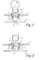
- Figure 1 is a vertical section through a first embodiment of the two-part connector; and
- Figure 2 is a vertical section through a second embodiment of the two-part connector.
- The mounting connector shown in Figure 1 comprises two
parts 1, 2 each of which is adapted to be fastened to one of the two bodies that are to be held together. The connector is especially suited for securing a blind or an auto visor (usually manufactured from a plastic sheet by vacuum forming) to the rear window of a motor car. The part 1 in the form of astud 7 is mounted on the window by gluing or alternatively to the bodywork of the car by means of selftapping screws. Theother part 2, in the form of a bushing is inserted through an opening in theplastic sheet 3, and has a collar adapted to engage the edge of the opening. Inside in the part 1 anannular projection 6 is provided which is able to slide onto part 1. The stud part 1 has an integral base plate 8, by means of which the part 1 is fastened to the body. The free end of the stud is rounded in order to facilitate insertion of thestud 7 in thepart 2. In an annular groove 9 around thestud 7 is inserted a slottedring 10 forming an undercut collar on the stud. The outer diameter of the slottedring 10 is larger than that of thestud 7, but its internal diameter is smaller than the diameter of the stud. Thering 10 is resilient and has a chamfer on the top of its outer edge, so that when thepart 2 is placed onto thestud 7, thering 10 is pressed into the groove 9 which is sufficiently deep to receive theentire ring 10, allowing theprojection 6 to pass the ring. Thereafter, the ring 9 snaps back and locks thepart 2. If it is desired to disassemble the twoparts 1 and 2, a tube shapedkey 12, the inner diameter of which corresponds to the outer diameter of thestud 7 and the outer diameter of which corresponds to the inner diameter of the tubular portion of thepart 2, is inserted into the annular gap between the two parts. Thekey 12 will then press thering 10 into the groove 9, allowing thepart 2 to be lifted off. - In the embodiment of Figure 2 parts corresponding to similar parts in Figure 1 bear the same reference numerals, and the description also covers these parts. In the embodiment of Figure 2 no ring is inserted into the groove 9 the upper portion of the
stud 7 in connection with the groove forming a undercut collar. On thepart 2 on the other hand a number of tongues 13 are arranged, which tongues have inwardly directedprojections 14 and a chamferedupper end 15. When thepart 2 is mounted on thestud 7, the tongues 13 will bend outwards resiliently until the projections snap into the groove 9, locking together the two parts. If thepart 2 is to be removed from the part 1, atubular key 12 is inserted_between the two parts, the key pressing the tongues outwards owing to the chamferedupper portion 15 of the tongues 13 into a recess 16 arranged behind the tongues. Thekey 12 and thepart 2 may then be removed from thestud 7.
Claims (7)
1. A two part connector comprising a bushing part and a stud part for insertion in the bushing part to engage one or more projections on one part behind one or more abutments on the other by resilient deformation of at least one the parts, the parts being resiliently deformable to disengage the projections and/or abutments'enabling separation of the two parts, by inserting a tubular key into an annular opening defined between the two parts.
2. A two part connector according to claim 1 in combination with a tubular key for enabling separation of the parts.
3. A connector according to claim 1 or claim 2 wherein the stud part is substantially cylindrical having an undercut annular collar and the bushing part has internal projections which are resiliently deformable to admit the stud and engage behind the collar.
4. A connector according to claim 1 in which the outer collar on the cylindrical stud is a slotted ring, the edge of the tubular key having an internal chamfer for cooperation with a corresponding chamfer on the slotted ring.
5. A connector according to any one of claims 1 to 3, in which the bushing has resilient tongues, carrying the projections and the tongues have a bevelled edge of the same width as the projections, the projection being arranged as an end stop for the inserted key.
6. A connector according to claim 5, wherein the tongues are fastened to an annular portion of the bushing, into which the stud is inserted, and which tongues are delimited by means of U-shaped cuttings in the side walls of the bushing.
7. A connector according to any one of claims 1 to 6 wherein the outer diameter of the key corresponds to the internal diameter of the bushing or the inner diameter of which corresponds to the outer diameter of the stud, and wherein the wall thickness of the tubular key is just greater than the relative resilient deformation effected during insertion of the stud part to engage the two parts.
Applications Claiming Priority (2)
| Application Number | Priority Date | Filing Date | Title |
|---|---|---|---|
| DK48984A DK149903C (en) | 1984-02-03 | 1984-02-03 | DECISION OF TWO OBJECTS TO THE OTHER AND KEY TO TRANSFER THE DECISION |
| DK489/84 | 1984-02-03 |
Publications (2)
| Publication Number | Publication Date |
|---|---|
| EP0163360A2 true EP0163360A2 (en) | 1985-12-04 |
| EP0163360A3 EP0163360A3 (en) | 1986-09-03 |
Family
ID=8094138
Family Applications (1)
| Application Number | Title | Priority Date | Filing Date |
|---|---|---|---|
| EP85300699A Withdrawn EP0163360A3 (en) | 1984-02-03 | 1985-02-01 | Two-part connector |
Country Status (4)
| Country | Link |
|---|---|
| EP (1) | EP0163360A3 (en) |
| JP (1) | JPS60184707A (en) |
| AU (1) | AU3828985A (en) |
| DK (1) | DK149903C (en) |
Cited By (5)
| Publication number | Priority date | Publication date | Assignee | Title |
|---|---|---|---|---|
| FR2594502A1 (en) * | 1986-02-17 | 1987-08-21 | Itw De France | FIXING DEVICE, IN PARTICULAR FOR PANELS |
| EP0754602A1 (en) * | 1995-07-21 | 1997-01-22 | Textron Inc. | Mounting assembly for air bag |
| GB2334298A (en) * | 1998-02-12 | 1999-08-18 | Piolax Inc | Trim clip with resilient latch |
| EP1209401A3 (en) * | 2000-11-23 | 2004-05-12 | Josef Kühlmann | Method of manufacturing a dimensionally stable tubular body from a strip of material and connector for manufacturing the tubular body |
| GB2413589A (en) * | 2004-04-28 | 2005-11-02 | Newfrey Llc | Fastener clamping member between two flanges |
Citations (8)
| Publication number | Priority date | Publication date | Assignee | Title |
|---|---|---|---|---|
| DE7721719U1 (en) * | N.V. Philips' Gloeilampenfabrieken, Eindhoven (Niederlande) | |||
| US3009381A (en) * | 1957-11-27 | 1961-11-21 | Illinois Tool Works | Stud and dished plastic fastening element |
| FR1363849A (en) * | 1963-07-23 | 1964-06-12 | Carr Fastener Co Ltd | Closing device and means for fixing it in an opening or cavity formed in a support |
| DE1475035A1 (en) * | 1965-12-01 | 1969-04-24 | Hellermann Gmbh P | Pair of fasteners |
| DE1400800A1 (en) * | 1961-10-13 | 1971-12-30 | Ft Products Ltd | Fasteners |
| DE2609094A1 (en) * | 1975-12-03 | 1977-09-08 | Raymond A Fa | Fastener for cables on sheet metal panels - has inward lugs for snap connection with stud on panel |
| FR2354470A1 (en) * | 1976-06-11 | 1978-01-06 | Itw Ateco Gmbh | FIXING DEVICE |
| DD158885A1 (en) * | 1981-05-18 | 1983-02-09 | Bernd Borrmann | SUNSCREEN WITH REAR VENTILATION |
-
1984
- 1984-02-03 DK DK48984A patent/DK149903C/en not_active IP Right Cessation
-
1985
- 1985-02-01 EP EP85300699A patent/EP0163360A3/en not_active Withdrawn
- 1985-02-01 AU AU38289/85A patent/AU3828985A/en not_active Abandoned
- 1985-02-02 JP JP1775585A patent/JPS60184707A/en active Pending
Patent Citations (8)
| Publication number | Priority date | Publication date | Assignee | Title |
|---|---|---|---|---|
| DE7721719U1 (en) * | N.V. Philips' Gloeilampenfabrieken, Eindhoven (Niederlande) | |||
| US3009381A (en) * | 1957-11-27 | 1961-11-21 | Illinois Tool Works | Stud and dished plastic fastening element |
| DE1400800A1 (en) * | 1961-10-13 | 1971-12-30 | Ft Products Ltd | Fasteners |
| FR1363849A (en) * | 1963-07-23 | 1964-06-12 | Carr Fastener Co Ltd | Closing device and means for fixing it in an opening or cavity formed in a support |
| DE1475035A1 (en) * | 1965-12-01 | 1969-04-24 | Hellermann Gmbh P | Pair of fasteners |
| DE2609094A1 (en) * | 1975-12-03 | 1977-09-08 | Raymond A Fa | Fastener for cables on sheet metal panels - has inward lugs for snap connection with stud on panel |
| FR2354470A1 (en) * | 1976-06-11 | 1978-01-06 | Itw Ateco Gmbh | FIXING DEVICE |
| DD158885A1 (en) * | 1981-05-18 | 1983-02-09 | Bernd Borrmann | SUNSCREEN WITH REAR VENTILATION |
Cited By (8)
| Publication number | Priority date | Publication date | Assignee | Title |
|---|---|---|---|---|
| FR2594502A1 (en) * | 1986-02-17 | 1987-08-21 | Itw De France | FIXING DEVICE, IN PARTICULAR FOR PANELS |
| EP0754602A1 (en) * | 1995-07-21 | 1997-01-22 | Textron Inc. | Mounting assembly for air bag |
| GB2334298A (en) * | 1998-02-12 | 1999-08-18 | Piolax Inc | Trim clip with resilient latch |
| GB2334298B (en) * | 1998-02-12 | 2000-01-19 | Piolax Inc | A part mounting structure |
| US6074150A (en) * | 1998-02-12 | 2000-06-13 | Piolax Inc. | Part mounting structure |
| EP1209401A3 (en) * | 2000-11-23 | 2004-05-12 | Josef Kühlmann | Method of manufacturing a dimensionally stable tubular body from a strip of material and connector for manufacturing the tubular body |
| GB2413589A (en) * | 2004-04-28 | 2005-11-02 | Newfrey Llc | Fastener clamping member between two flanges |
| US7257867B2 (en) | 2004-04-28 | 2007-08-21 | Newfrey Llc | Clip for attaching two members |
Also Published As
| Publication number | Publication date |
|---|---|
| DK48984D0 (en) | 1984-02-03 |
| DK149903B (en) | 1986-10-20 |
| DK149903C (en) | 1987-05-18 |
| DK48984A (en) | 1985-08-04 |
| EP0163360A3 (en) | 1986-09-03 |
| AU3828985A (en) | 1985-08-08 |
| JPS60184707A (en) | 1985-09-20 |
Similar Documents
| Publication | Publication Date | Title |
|---|---|---|
| US4668145A (en) | Fastener for coupling together two panels in face-to-face relation | |
| US5435159A (en) | Lock housing with flange for fitting in an aperture in a thin wall like a sheet metal cupboard door or sheet metal casing cover | |
| CA1077244A (en) | Fixing device | |
| US4828444A (en) | Plastic push-on nut | |
| US4542922A (en) | Fitting for connecting circumferentially ribbed insulating tubes of plastic | |
| US5931035A (en) | Cylinder type lock arrangement | |
| US7360964B2 (en) | Joint structure | |
| CA2040260A1 (en) | Vehicle trim assembly and fastener therefor | |
| KR101133305B1 (en) | Steering lock assembly | |
| US4932105A (en) | Self locking attaching system | |
| US6371619B1 (en) | Vehicle exterior mirror | |
| EP0616140A2 (en) | Structure for mounting mechanical element to shaft | |
| CN106979201B (en) | Fastener clip assembly with funnel guide | |
| US4819133A (en) | Replaceable headlamp assembly | |
| EP0163360A2 (en) | Two-part connector | |
| EP0557082B1 (en) | Vehicular sun visors | |
| US5069013A (en) | Casement window fastening system | |
| US6178605B1 (en) | System for coupling and fixing plastic material accessories to modular self-supporting elements and the latter to the vehicle bodywork | |
| EP0817328B1 (en) | L-shaped bulb connector | |
| US4586736A (en) | Flush mounting cup for cabinet latch | |
| JPH0942252A (en) | Fastener | |
| US6394814B2 (en) | Electrical plug-in connector for providing an electrical connection between two regions separated by a partition wall | |
| CA1156285A (en) | Antitheft device for motor vehicles | |
| EP0829929B1 (en) | Electrical connector for attachment in a panel opening | |
| US4375897A (en) | Coupling for joining a drive wire to a belt transfer member |
Legal Events
| Date | Code | Title | Description |
|---|---|---|---|
| PUAI | Public reference made under article 153(3) epc to a published international application that has entered the european phase |
Free format text: ORIGINAL CODE: 0009012 |
|
| AK | Designated contracting states |
Designated state(s): AT BE CH DE FR GB IT LI LU NL SE |
|
| PUAL | Search report despatched |
Free format text: ORIGINAL CODE: 0009013 |
|
| AK | Designated contracting states |
Kind code of ref document: A3 Designated state(s): AT BE CH DE FR GB IT LI LU NL SE |
|
| STAA | Information on the status of an ep patent application or granted ep patent |
Free format text: STATUS: THE APPLICATION IS DEEMED TO BE WITHDRAWN |
|
| 18D | Application deemed to be withdrawn |
Effective date: 19870504 |
|
| RIN1 | Information on inventor provided before grant (corrected) |
Inventor name: HANSEN, HELGE |