EP0162734B1 - Laser surveying equipment - Google Patents
Laser surveying equipment Download PDFInfo
- Publication number
- EP0162734B1 EP0162734B1 EP85400559A EP85400559A EP0162734B1 EP 0162734 B1 EP0162734 B1 EP 0162734B1 EP 85400559 A EP85400559 A EP 85400559A EP 85400559 A EP85400559 A EP 85400559A EP 0162734 B1 EP0162734 B1 EP 0162734B1
- Authority
- EP
- European Patent Office
- Prior art keywords
- laser
- laser beam
- light
- surveying equipment
- prism
- Prior art date
- Legal status (The legal status is an assumption and is not a legal conclusion. Google has not performed a legal analysis and makes no representation as to the accuracy of the status listed.)
- Expired
Links
- 230000004907 flux Effects 0.000 claims description 13
- 230000003287 optical effect Effects 0.000 claims description 9
- 239000004065 semiconductor Substances 0.000 claims description 9
- 239000000725 suspension Substances 0.000 claims description 4
- 239000011521 glass Substances 0.000 description 3
- 238000005286 illumination Methods 0.000 description 3
Images


Classifications
-
- G—PHYSICS
- G01—MEASURING; TESTING
- G01C—MEASURING DISTANCES, LEVELS OR BEARINGS; SURVEYING; NAVIGATION; GYROSCOPIC INSTRUMENTS; PHOTOGRAMMETRY OR VIDEOGRAMMETRY
- G01C15/00—Surveying instruments or accessories not provided for in groups G01C1/00 - G01C13/00
- G01C15/002—Active optical surveying means
- G01C15/004—Reference lines, planes or sectors
Definitions
- the present invention relates to an improvement of a laser surveying equipment of a type which carries out a survey by scanning laser beam radiated toward a surveying object within a horizontal plane, or directing the same in the perpendicular direction.
- a laser surveying equipment which is used for a leveling by radiating laser beam scanned within a horizontal plane toward a surveying object and detecting the height of position on a surveying object where the laser beam has reached either with surveyor's naked eyes or photoelectrically, or which is used to shiftingly set a datum point on the earth in the perpendicular direction by directing laser beam in the perpendicular direction.
- the laser beam since the laser beam is always required to be scanned within a genuin horizontal plane or to be directed in the perpendicular direction, when the equipment is to be installed, it must be adjusted with special care.
- a laser surveying equipment wherein an adjusting device is incorporated so that even in the case the equipment should be declined, the radiating direction of the laser beam would be directed toward a preset direction.
- DE-B-1208508 discloses that a two-faced reflection member is suspended for vertical inversion. This member allowed only an amendment of the luminous beam inclination in a surface parallel to the sheet. Therefore, it can not amend the inclination in a different direction, like on a surface perpendicular to the sheet, for instance.
- CH-A-310861 discloses that a one-faced reflection member is suspended. This member can only amend the inclination on the vertical surface, i.e. parallel to the sheet. But, it cannot carry out an amendment on an other surface, like on a surface perpendicular to the sheet.
- this equipment comprising feedback opto-electronical devices is systematically complicated and large sized.
- DE-A-2311907 discloses that a two-faced reflection member is suspended for horizontal inversion. This member can amend the luminous beam inclination on the sheet surface and not on an other surface like a surface perpendicular to the sheet.
- the present invention was accomplished in order to overcome the above mentioned disadvantages.
- the invention is set out in claim 1, scanning can be always carried out almost in any directions.
- Fig. 1 and Fig. 2 are schematic views for explaining the principle of the present invention.
- 1 denotes a laser surveying equipment, from which a mounting table 3 is suspended by four ribbons 2.
- a Porro prism 4 is firmly secured to said table 3.
- a light source 5 is arranged beneath the Porro prism 4.
- a projection lens 6 having a focal distance f o and adapted to form the light from said light source 5 into a parallel flux of light.
- the length l of the ribbons 2 is set to be one half of the focal distance f o .
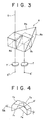
- FIG. 3 A specific example of the Porro prism 4 is illustrated in Fig. 3.
- the light emitted from a first light source 5' is directed toward the upward direction through a converging lens 7, reflected on first through fourth reflecting surfaces R1, R2, R3, and R4, and radiated upward.
- This radiating direction S is in agreement with the optical axis direction of the light (directed toward the upward direction through a converging lens 7') from a second light source 5'' provided beneath the fourth reflecting surface R4. That is to say, two different flux of light is brought to be duplicated one upon the other in the same radiating direction S.
- the reflecting surface R3 is formed into a reflecting surface having a wave length selecting property which reflects the infrared light and allows the visible light to penetrate therethrough, two flux of light of the infrared light and the visible light can be projected without producing a loss of the light amount.
- Fig. 4 illustrates an example of another Porro prism 4' for an erected normal image.
- the flux of light from a light source 5A is reflected on first through fourth reflecting surfaces r1, r2, r3 and r4 respectively, and the incoming light axis and the outgoing light axis are in agreement with respect to each other.
- Fig. 5 illustrates a laser surveying equipment constituted according to the principle as described in the foregoing.
- An equipment 11 is installed on an adjustable table 12.
- a holder 13 is secured to a generally central portion at the bottom of said equipment 11.
- a semiconductor laser 14 adapted to serve as a laser beam luminous section is arranged, and a projection lens 15 is arranged upward thereof.
- a light source of visible light is ommited from the figure, since the same is already described with respect to Fig. 3.
- a Porro prism 16 for an erected normal image constituting a suspending reflection member is secured to a suspension table 17 above the projection lens 15.
- Said suspension table 17 is suspended by a ribbon 19 formed of four plastic strings arranged symmetric with respect to a top board of a supporting frame 18 constituting a part of the equipment 11. Further, beneath the top board of said supporting frame 18, another supporting frame 20 is mounted. And a parallel plane glass 21 for adjustment is fitted to said supporting frame 20.
- a lens holder 22 is mounted to the top board of said supporting frame 18, and a projection lens 23 comprising two groups of lenses 231, 232 is secured to the lens holder 22.
- These two groups of lenses 231, 232 are constituted as such that they are adjustable for movement as a unit and that the distance between the lenses 231, 232 is adjustable.
- the laser beam radiated from the semiconductor laser 14 passes through the converging lens 15, the Porro prism 16, the parallel plane glass 21 and the projection lens 23, and finally radiated upward.
- the equipment 1 is provided at the upper portion thereof with a bearing 24, on which a rotary shaft 26 including a pulley 25 is carried. Said pulley 25 is wound around a belt 30 wound around another pulley 29 axially attached to a motor 28. Because of the foregoing arrangement, the rotary shaft 26 is driven for rotation. Also, at the upper end portion of the rotary shaft 26, a prism house 32 including a pentagonal prism 31 constituting a rotary reflection member is provided at the upper end portion of the rotary shaft 26, a prism house 32 including a pentagonal prism 31 constituting a rotary reflection member is provided. At the incoming light side of said pentagonal prism 31, a window 32A for the incoming light is provided, while at the outgoing light side thereof provided is a prism 33 for adjustment.
- Said prism house 32 is easily detachably attached to the equipment 1 by means of a simple securing means such as, for example, a machine screw. That is, when the prism house 32 is removed, it functions as an apparatus which projects laser beam upward in the perpendicular direction.
- the outgoing light reflected by means of said pentagonal prism 31 is radiated toward a surveying point as a surveying object, and scanned over the surveying object according to the rotation of the rotary shaft 26.
- a battery box 35 containing therein a battery 34 served as a power source is provided, so that the electric system is operated by a switch 36.
- the laser surveying equipment as shown in Fig. 5 is constituted based on the principle as shown in Fig. 1 and Fig. 2, even if the equipment 1 should be declined and the radiating direction of the laser beam from the semiconductor laser 14 should be displaced, since the length of the ribbon 19 is set to be one half of the focal distance of the projection lens 23, the optical axis of the laser beam radiated from the Porro prism 16 is directed toward the perpendicular direction. Accordingly, the flux of light radiated toward the surveying object from the pentagonal prism 31 is always scanned within a horizontal plane.
- an invisible infrared light is used as a laser beam radiated from the semiconductor laser 14.
- a detector adapted to photoelectrically detect the infrared laser light is vertically movably mounted on a staff erected at the surveying point in order to carry out a horizontal survey. Because of the foregoing, since the position of the laser beam entering into the detector is often difficult to be determined in a stage prior to the surveying, a visible light source is used in order to detect the approximate position with ease.
- the first light source 5' as shown in Fig. 3 may be used as the semiconductor laser, and the second light source 5'' may be used as the lamp for radiating a visible light.
- the projection lens 23 constituted with two groups of lenses can also be moved as a unit in order to form the incoming laser beam into a parallel flux of light. Furthermore, by changing the distance between the two groups of the lenses, the focal distance thereof can be adjusted, as well.
- the parallel plane glass 21 is arranged to be declinable, and the incoming laser beam is adjustable with respect to its outgoing direction.
- the Porro prism 16 as a suspending reflection member may be a prism for an erecting normal image, such as a combination of a plurality of rectangular prisms as shown in Fig. 3, or alternatively a combination of a roof prism and a trapezoidal prism as shown in Fig. 4.
Landscapes
- Physics & Mathematics (AREA)
- Engineering & Computer Science (AREA)
- General Physics & Mathematics (AREA)
- Radar, Positioning & Navigation (AREA)
- Remote Sensing (AREA)
- Measurement Of Optical Distance (AREA)
- Optical Radar Systems And Details Thereof (AREA)
- Photometry And Measurement Of Optical Pulse Characteristics (AREA)
- Mechanical Optical Scanning Systems (AREA)
Description
- The present invention relates to an improvement of a laser surveying equipment of a type which carries out a survey by scanning laser beam radiated toward a surveying object within a horizontal plane, or directing the same in the perpendicular direction.
- There is known a laser surveying equipment which is used for a leveling by radiating laser beam scanned within a horizontal plane toward a surveying object and detecting the height of position on a surveying object where the laser beam has reached either with surveyor's naked eyes or photoelectrically, or which is used to shiftingly set a datum point on the earth in the perpendicular direction by directing laser beam in the perpendicular direction. In this case, since the laser beam is always required to be scanned within a genuin horizontal plane or to be directed in the perpendicular direction, when the equipment is to be installed, it must be adjusted with special care.
- In view of the above, a laser surveying equipment is proposed, wherein an adjusting device is incorporated so that even in the case the equipment should be declined, the radiating direction of the laser beam would be directed toward a preset direction.
- As one of this kind of laser surveying equipment, there is known equipment which is constituted in such a manner as that an illumination tube having a radiating face of laser beam at the lower end thereof is suspended from the equipment thereby directing the radiating direction of laser beam in the perpendicular direction in order to scan within a horizontal plane through a rotary deflecting member provided beneath, or so that the laser beam can be directly directed toward the perpendicular direction.
- However, with the above constitution, an electric wire adapted to supply power for operating the laser illumination tube often disturbs the effective suspension of the laser illumination tube. Besides, highly accurate adjustment can not be obtained in this prior art.
- Also, there is known another conventional equipment, wherein laser beam is radiated from a semiconductor laser and beneath this semiconductor laser a projection lens for forming outgoing laser beam into a parallel flux of light is suspended thereby directing the laser beam from this projection lens directly in the perpendicular direction, or scanning it within a horizontal plane by a rotary pentagonal prism.
- However, with this constitution, there is such a disadvantage as that since the radiating direction of the laser beam is downward, when it is scanned by the rotary pentagonal prism, the laser beam directed in parallel is blocked by a framework of the equipment. Accordingly, surveying accuracy with respect to a certain direction is reduced, or otherwise it is practically impossible to make a survey.
- DE-B-1208508 discloses that a two-faced reflection member is suspended for vertical inversion. This member allowed only an amendment of the luminous beam inclination in a surface parallel to the sheet. Therefore, it can not amend the inclination in a different direction, like on a surface perpendicular to the sheet, for instance.
- CH-A-310861 discloses that a one-faced reflection member is suspended. This member can only amend the inclination on the vertical surface, i.e. parallel to the sheet. But, it cannot carry out an amendment on an other surface, like on a surface perpendicular to the sheet.
- Proceedings of the iEEE, Vol.70, No.6, June 1982, pp. 635-640 discloses that the equipment is autolevelled by inclining it with a motor, monitored by a levelsensor output signal. The equipment in the reference needs a level sensor a driving source and a driving system for inclining it, each of which our invention does not need.
- Further, this equipment comprising feedback opto-electronical devices is systematically complicated and large sized.
- DE-A-2311907 discloses that a two-faced reflection member is suspended for horizontal inversion. This member can amend the luminous beam inclination on the sheet surface and not on an other surface like a surface perpendicular to the sheet.
- The present invention was accomplished in order to overcome the above mentioned disadvantages.
- It is therefore an object of the present invention to provide a laser surveying equipment which can be adjusted in order to always scan the laser beam radiated toward a surveying object within a genuine horizontal plane or direct it toward a genuine perpendicular direction.
- The invention is set out in claim 1, scanning can be always carried out almost in any directions.
- The invention will become more apparent to those skilled in the art upon reading the following detailed description with reference to the accompanying drawings in which :
-
- Fig. 1 and Fig. 2 are schematic constitutional views of an optical system in order to explain the principle of the present invention, wherein Fig. 1 is a view showing when a laser surveying equipment according to the invention is not declined, Fig. 2 is a view similar to the above but showing when the equipment is declined;
- Fig. 3 is a perspective view for explaining a Porro prism;
- Fig. 4 is likewise a perspective view for explaining another Porro prism; and
- Fig. 5 is a vertical sectional view showing the laser surveying equipment according to one preferred embodiment of the present invention.
- Fig. 1 and Fig. 2 are schematic views for explaining the principle of the present invention. In the figures, 1 denotes a laser surveying equipment, from which a mounting table 3 is suspended by four
ribbons 2. A Porroprism 4 is firmly secured to said table 3. Alight source 5 is arranged beneath the Porroprism 4. While above the Porroprism 4, aprojection lens 6 having a focal distance fo and adapted to form the light from saidlight source 5 into a parallel flux of light. In this example, the length ℓ of theribbons 2 is set to be one half of the focal distance fo. - With the above constitution, when the equipment 1 is declined by angle ϑo with respect to perpendicular axis E, said Porro
prism 4 is moved by distance H₁,
i.e.,
projection lens 6. In this case, the ϑo is a microangle and such a relation as ϑo ≒ tan ϑo is obtained. On the other hand, since thelight source 5 is positioned on the optical axis L of theprojection lens 6, flux of light entered into thePorro prism 4 is reflected four times therein, and then directed toward the direction away by distance H₂, i.e., from the optical axis L. Accordingly, the flux of light entered into the
projection lens 6 is moved in parallel relation by foϑo before the equipment 1 is declined. Because of the foregoing, flux of light P passed through theprojection lens 6 is directed toward the angle ϑ₁ direction with respect to axial line L' parallel to the optical axis L. Such directed direction is on focal position F of theprojection lens 6. In other words, a relation
projection lens 6 becomes always parallel to the perpendicular direction E. Such a phenomenon is likewise produced, even when the equipment 1 is declined in the perpendicular direction with respect to a surface of paper. - A specific example of the Porro
prism 4 is illustrated in Fig. 3. The light emitted from a first light source 5' is directed toward the upward direction through a converginglens 7, reflected on first through fourth reflecting surfaces R₁, R₂, R₃, and R₄, and radiated upward. This radiating direction S is in agreement with the optical axis direction of the light (directed toward the upward direction through a converging lens 7') from a second light source 5'' provided beneath the fourth reflecting surface R₄. That is to say, two different flux of light is brought to be duplicated one upon the other in the same radiating direction S. When a semiconductor laser radiating infrared light is employed as the first light source 5' and a light source of visible light is employed as the second light source 5'', if the reflecting surface R₃ is formed into a reflecting surface having a wave length selecting property which reflects the infrared light and allows the visible light to penetrate therethrough, two flux of light of the infrared light and the visible light can be projected without producing a loss of the light amount. - Fig. 4 illustrates an example of another Porro prism 4' for an erected normal image. In the figure, the flux of light from a
light source 5A is reflected on first through fourth reflecting surfaces r1, r2, r3 and r4 respectively, and the incoming light axis and the outgoing light axis are in agreement with respect to each other. - Fig. 5 illustrates a laser surveying equipment constituted according to the principle as described in the foregoing. An equipment 11 is installed on an adjustable table 12. A
holder 13 is secured to a generally central portion at the bottom of said equipment 11. At the lower portion of saidholder 13, asemiconductor laser 14 adapted to serve as a laser beam luminous section is arranged, and aprojection lens 15 is arranged upward thereof. A light source of visible light is ommited from the figure, since the same is already described with respect to Fig. 3. A Porroprism 16 for an erected normal image constituting a suspending reflection member is secured to a suspension table 17 above theprojection lens 15. Said suspension table 17 is suspended by aribbon 19 formed of four plastic strings arranged symmetric with respect to a top board of a supportingframe 18 constituting a part of the equipment 11. Further, beneath the top board of said supportingframe 18, another supportingframe 20 is mounted. And aparallel plane glass 21 for adjustment is fitted to said supportingframe 20. - A
lens holder 22 is mounted to the top board of said supportingframe 18, and aprojection lens 23 comprising two groups oflenses 23₁, 23₂ is secured to thelens holder 22. These two groups oflenses 23₁, 23₂ are constituted as such that they are adjustable for movement as a unit and that the distance between thelenses 23₁, 23₂ is adjustable. - In this way, the laser beam radiated from the
semiconductor laser 14 passes through the converginglens 15, the Porroprism 16, theparallel plane glass 21 and theprojection lens 23, and finally radiated upward. - On the other hand, the equipment 1 is provided at the upper portion thereof with a
bearing 24, on which arotary shaft 26 including apulley 25 is carried. Saidpulley 25 is wound around abelt 30 wound around anotherpulley 29 axially attached to amotor 28. Because of the foregoing arrangement, therotary shaft 26 is driven for rotation. Also, at the upper end portion of therotary shaft 26, aprism house 32 including apentagonal prism 31 constituting a rotary reflection member is provided. At the incoming light side of saidpentagonal prism 31, a window 32A for the incoming light is provided, while at the outgoing light side thereof provided is aprism 33 for adjustment. Saidprism house 32 is easily detachably attached to the equipment 1 by means of a simple securing means such as, for example, a machine screw. That is, when theprism house 32 is removed, it functions as an apparatus which projects laser beam upward in the perpendicular direction. The outgoing light reflected by means of saidpentagonal prism 31 is radiated toward a surveying point as a surveying object, and scanned over the surveying object according to the rotation of therotary shaft 26. - At one side of the equipment 1, a
battery box 35 containing therein abattery 34 served as a power source is provided, so that the electric system is operated by aswitch 36. - As described in the foregoing, since the laser surveying equipment as shown in Fig. 5 is constituted based on the principle as shown in Fig. 1 and Fig. 2, even if the equipment 1 should be declined and the radiating direction of the laser beam from the
semiconductor laser 14 should be displaced, since the length of theribbon 19 is set to be one half of the focal distance of theprojection lens 23, the optical axis of the laser beam radiated from thePorro prism 16 is directed toward the perpendicular direction. Accordingly, the flux of light radiated toward the surveying object from thepentagonal prism 31 is always scanned within a horizontal plane. - Generally, an invisible infrared light is used as a laser beam radiated from the
semiconductor laser 14. A detector adapted to photoelectrically detect the infrared laser light is vertically movably mounted on a staff erected at the surveying point in order to carry out a horizontal survey. Because of the foregoing, since the position of the laser beam entering into the detector is often difficult to be determined in a stage prior to the surveying, a visible light source is used in order to detect the approximate position with ease. In other words, the first light source 5' as shown in Fig. 3 may be used as the semiconductor laser, and the second light source 5'' may be used as the lamp for radiating a visible light. - Also, the
projection lens 23 constituted with two groups of lenses can also be moved as a unit in order to form the incoming laser beam into a parallel flux of light. Furthermore, by changing the distance between the two groups of the lenses, the focal distance thereof can be adjusted, as well. In addition, theparallel plane glass 21 is arranged to be declinable, and the incoming laser beam is adjustable with respect to its outgoing direction. ThePorro prism 16 as a suspending reflection member may be a prism for an erecting normal image, such as a combination of a plurality of rectangular prisms as shown in Fig. 3, or alternatively a combination of a roof prism and a trapezoidal prism as shown in Fig. 4.
Claims (6)
- A laser surveying equipment comprising :
a laser beam luminous section ;
a four-faced reflection erected normal image prism suspended in such a manner so as to reflect laser beam radiated from said laser beam luminous section upward and always to direct optical axis of such reflected light in the perpendicular direction ; and
a projection lens system adapted to project the laser beam after forming it into a generally parallel flux of light. - A laser surveying equipment according to claim 1, characterized in that :
a parallel flux of light obtained from a projection lens system displaces an optical path toward a surveying object within a horizontal plane by approximately 90 degrees by the rotation of a rotable reflection member. - A laser surveying equipment according to claim 1 or claim 2, wherein said laser beam luminous section is a semiconductor laser.
- A laser surveying equipment according to claim 1 or claim 2, wherein said erected normal image prism is a Porro prism.
- A laser surveying equipment according to claim 1 or claim 2, wherein said erected normal image prism is suspended by a suspension wire formed lengthwise to be generally one half of focal distance of said projection lens system.
- A laser surveying equipment according to claim 1 or claim 2, wherein said erected normal image prism is suspended by four suspending wires.
Applications Claiming Priority (4)
| Application Number | Priority Date | Filing Date | Title |
|---|---|---|---|
| JP55288/84 | 1984-03-24 | ||
| JP5528884A JPS60200117A (en) | 1984-03-24 | 1984-03-24 | Laser surveying machine |
| JP59356/84 | 1984-03-29 | ||
| JP5935684A JPS60203807A (en) | 1984-03-29 | 1984-03-29 | Laser measuring machine |
Publications (3)
| Publication Number | Publication Date |
|---|---|
| EP0162734A2 EP0162734A2 (en) | 1985-11-27 |
| EP0162734A3 EP0162734A3 (en) | 1988-08-03 |
| EP0162734B1 true EP0162734B1 (en) | 1991-10-23 |
Family
ID=26396184
Family Applications (1)
| Application Number | Title | Priority Date | Filing Date |
|---|---|---|---|
| EP85400559A Expired EP0162734B1 (en) | 1984-03-24 | 1985-03-22 | Laser surveying equipment |
Country Status (3)
| Country | Link |
|---|---|
| US (1) | US4781457A (en) |
| EP (1) | EP0162734B1 (en) |
| DE (2) | DE3584470D1 (en) |
Families Citing this family (23)
| Publication number | Priority date | Publication date | Assignee | Title |
|---|---|---|---|---|
| US4662707A (en) * | 1985-09-27 | 1987-05-05 | Spectra-Physics, Inc. | Lighthouse structure and compensating lens in reference laser beam projecting apparatus |
| JPH0721411B2 (en) * | 1987-01-20 | 1995-03-08 | 株式会社ソキア | Optical leveling device |
| JPH02116708A (en) * | 1988-10-27 | 1990-05-01 | Asahi Seimitsu Kk | Device for emitting reference beam of measuring instrument |
| US4993161A (en) * | 1990-01-04 | 1991-02-19 | David White, Inc. | Laser beam level instrument |
| US5108177A (en) * | 1990-09-12 | 1992-04-28 | Laserline, Inc. | Two-axis levelling instrument with a single pendulum for projecting a level laser beam |
| US5182863A (en) * | 1990-10-22 | 1993-02-02 | Spectra-Physics Laserplane, Inc. | Automatic plumb and level tool with acoustic measuring capability |
| US5075977A (en) * | 1990-10-22 | 1991-12-31 | Spectra-Physics, Inc. | Automatic plumb and level tool |
| US5144487A (en) * | 1991-09-03 | 1992-09-01 | Pacific Laser | Portable laser device for alignment tasks |
| US5459932A (en) * | 1993-08-27 | 1995-10-24 | Levelite Technology, Inc. | Automatic level and plumb tool |
| US5617202A (en) * | 1994-05-24 | 1997-04-01 | Levelite Technology, Inc. | Diode laser co-linear and intersecting light beam generator |
| US5610711A (en) * | 1995-12-22 | 1997-03-11 | Levelite Technology Inc. | Remote pointing system for a self-leveling laser instrument |
| US6014211A (en) * | 1998-01-20 | 2000-01-11 | Laser Reference | Device and method for providing a laser level plane |
| US6209219B1 (en) | 1998-07-30 | 2001-04-03 | The Stanley Works | Measuring device with housing orientation indicator and position transferring focused light-beam source |
| AUPP656398A0 (en) * | 1998-10-19 | 1998-11-05 | Emtech Safety Products Pty Ltd | Safety/warning device |
| US6542304B2 (en) | 1999-05-17 | 2003-04-01 | Toolz, Ltd. | Laser beam device with apertured reflective element |
| US6332276B1 (en) | 2000-03-30 | 2001-12-25 | Ronnie L. Mangel | Articulate laser degree finder |
| JP3840119B2 (en) * | 2002-02-08 | 2006-11-01 | 株式会社ソキア | Laser centripetal device |
| CN2588326Y (en) * | 2002-12-27 | 2003-11-26 | 南京泉峰国际贸易有限公司 | Laser line marking device |
| CN101078623B (en) | 2006-05-26 | 2010-05-12 | 南京德朔实业有限公司 | Self-leveling laser marking device and control method thereof |
| US7497018B2 (en) | 2006-05-26 | 2009-03-03 | William Hersey | Laser-based alignment tool |
| USD571237S1 (en) | 2006-12-20 | 2008-06-17 | Pls-Pacific Laser Systems, Llc | Laser level detector |
| CN201035148Y (en) | 2007-01-19 | 2008-03-12 | 南京德朔实业有限公司 | laser range finder |
| CN201035149Y (en) | 2007-01-19 | 2008-03-12 | 南京德朔实业有限公司 | laser range finder |
Family Cites Families (7)
| Publication number | Priority date | Publication date | Assignee | Title |
|---|---|---|---|---|
| CH310861A (en) * | 1949-11-09 | 1955-11-15 | Zeiss Carl Fa | Device for monitoring small inclinations of a device in relation to a reference line. |
| DE1208508B (en) * | 1958-05-21 | 1966-01-05 | Jenoptik Jena Gmbh | Device for stabilizing the finish line of an optical device |
| JPS5225104B2 (en) * | 1972-03-09 | 1977-07-05 | ||
| US3936197A (en) * | 1974-05-06 | 1976-02-03 | Laser Alignment, Inc. | Self-leveling laser assembly |
| DE2549218A1 (en) * | 1974-11-05 | 1976-05-06 | Secretary Industry Brit | OPTICAL DEVICE FOR DETERMINING AXES |
| US4221483A (en) * | 1978-11-20 | 1980-09-09 | Spectra-Physics, Inc. | Laser beam level instrument |
| EP0185363A3 (en) * | 1984-09-14 | 1988-07-27 | Asahi Precision Co., Ltd. | Automatic compensator for compensating collimation error due to two-directional inclination in surveying instruments |
-
1985
- 1985-03-22 DE DE8585400559T patent/DE3584470D1/en not_active Expired - Lifetime
- 1985-03-22 DE DE198585400559T patent/DE162734T1/en active Pending
- 1985-03-22 EP EP85400559A patent/EP0162734B1/en not_active Expired
- 1985-03-25 US US06/715,571 patent/US4781457A/en not_active Expired - Lifetime
Also Published As
| Publication number | Publication date |
|---|---|
| DE3584470D1 (en) | 1991-11-28 |
| US4781457A (en) | 1988-11-01 |
| DE162734T1 (en) | 1986-08-14 |
| EP0162734A2 (en) | 1985-11-27 |
| EP0162734A3 (en) | 1988-08-03 |
Similar Documents
| Publication | Publication Date | Title |
|---|---|---|
| US4781457A (en) | Laser surveying equipment | |
| US5144486A (en) | Laser beam apparatus for providing multiple reference beams | |
| US5218770A (en) | Surveying machine for construction work | |
| US5610711A (en) | Remote pointing system for a self-leveling laser instrument | |
| US6295174B1 (en) | Reflective prism device | |
| US4955975A (en) | Rainbow forming device | |
| CA2116445A1 (en) | Portable laser device for alignment tasks | |
| JPH07198382A (en) | Laser survey system | |
| US3966328A (en) | Device for generating a spatial reference plane | |
| JP2793740B2 (en) | Surveying instrument | |
| US4770480A (en) | Apparatus and method for providing multiple reference laser beams | |
| EP0987517B1 (en) | Automatic survey instrument | |
| US4560866A (en) | Image pick-up apparatus with folding optics | |
| EP0366150B1 (en) | Datum beam projecting apparatus for use with surveying equipment | |
| US6088623A (en) | System and method for leveling an apparatus | |
| RU2089853C1 (en) | Device setting light plane and unit scanning laser light beam to plane | |
| JPH047809B2 (en) | ||
| US4142800A (en) | Automatic level | |
| JPH0432967B2 (en) | ||
| JPH047165B2 (en) | ||
| JPS61281914A (en) | surveying equipment | |
| JPS63279113A (en) | Horizontality/verticality measuring apparatus | |
| JP3454861B2 (en) | Reference plane setting device | |
| SE8605575D0 (en) | DEVICE FOR AN OPTICAL INSTRUMENT | |
| SU1573342A1 (en) | Arrangement for checking rectilinearity |
Legal Events
| Date | Code | Title | Description |
|---|---|---|---|
| PUAI | Public reference made under article 153(3) epc to a published international application that has entered the european phase |
Free format text: ORIGINAL CODE: 0009012 |
|
| AK | Designated contracting states |
Designated state(s): CH DE FR GB LI SE |
|
| EL | Fr: translation of claims filed | ||
| DET | De: translation of patent claims | ||
| PUAL | Search report despatched |
Free format text: ORIGINAL CODE: 0009013 |
|
| AK | Designated contracting states |
Kind code of ref document: A3 Designated state(s): CH DE FR GB LI SE |
|
| 17P | Request for examination filed |
Effective date: 19890107 |
|
| RAP1 | Party data changed (applicant data changed or rights of an application transferred) |
Owner name: KABUSHIKI KAISHA TOPCON |
|
| 17Q | First examination report despatched |
Effective date: 19900507 |
|
| GRAA | (expected) grant |
Free format text: ORIGINAL CODE: 0009210 |
|
| AK | Designated contracting states |
Kind code of ref document: B1 Designated state(s): CH DE FR GB LI SE |
|
| REF | Corresponds to: |
Ref document number: 3584470 Country of ref document: DE Date of ref document: 19911128 |
|
| ET | Fr: translation filed | ||
| PGFP | Annual fee paid to national office [announced via postgrant information from national office to epo] |
Ref country code: GB Payment date: 19920310 Year of fee payment: 8 |
|
| PGFP | Annual fee paid to national office [announced via postgrant information from national office to epo] |
Ref country code: FR Payment date: 19920326 Year of fee payment: 8 |
|
| PLBE | No opposition filed within time limit |
Free format text: ORIGINAL CODE: 0009261 |
|
| STAA | Information on the status of an ep patent application or granted ep patent |
Free format text: STATUS: NO OPPOSITION FILED WITHIN TIME LIMIT |
|
| 26N | No opposition filed | ||
| PG25 | Lapsed in a contracting state [announced via postgrant information from national office to epo] |
Ref country code: GB Effective date: 19930322 |
|
| GBPC | Gb: european patent ceased through non-payment of renewal fee |
Effective date: 19930322 |
|
| PG25 | Lapsed in a contracting state [announced via postgrant information from national office to epo] |
Ref country code: FR Effective date: 19931130 |
|
| REG | Reference to a national code |
Ref country code: FR Ref legal event code: ST |
|
| EAL | Se: european patent in force in sweden |
Ref document number: 85400559.2 |
|
| PGFP | Annual fee paid to national office [announced via postgrant information from national office to epo] |
Ref country code: SE Payment date: 20020225 Year of fee payment: 18 |
|
| PGFP | Annual fee paid to national office [announced via postgrant information from national office to epo] |
Ref country code: CH Payment date: 20020326 Year of fee payment: 18 |
|
| PGFP | Annual fee paid to national office [announced via postgrant information from national office to epo] |
Ref country code: DE Payment date: 20020516 Year of fee payment: 18 |
|
| PG25 | Lapsed in a contracting state [announced via postgrant information from national office to epo] |
Ref country code: SE Free format text: LAPSE BECAUSE OF NON-PAYMENT OF DUE FEES Effective date: 20030323 |
|
| PG25 | Lapsed in a contracting state [announced via postgrant information from national office to epo] |
Ref country code: LI Free format text: LAPSE BECAUSE OF NON-PAYMENT OF DUE FEES Effective date: 20030331 Ref country code: CH Free format text: LAPSE BECAUSE OF NON-PAYMENT OF DUE FEES Effective date: 20030331 |
|
| PG25 | Lapsed in a contracting state [announced via postgrant information from national office to epo] |
Ref country code: DE Free format text: LAPSE BECAUSE OF NON-PAYMENT OF DUE FEES Effective date: 20031001 |
|
| EUG | Se: european patent has lapsed | ||
| REG | Reference to a national code |
Ref country code: CH Ref legal event code: PL |