EP0162345B1 - Method of forming a chemical phosphate coating on the surface of steel - Google Patents
Method of forming a chemical phosphate coating on the surface of steel Download PDFInfo
- Publication number
- EP0162345B1 EP0162345B1 EP85105225A EP85105225A EP0162345B1 EP 0162345 B1 EP0162345 B1 EP 0162345B1 EP 85105225 A EP85105225 A EP 85105225A EP 85105225 A EP85105225 A EP 85105225A EP 0162345 B1 EP0162345 B1 EP 0162345B1
- Authority
- EP
- European Patent Office
- Prior art keywords
- bath
- reaction
- ions
- steel
- orp
- Prior art date
- Legal status (The legal status is an assumption and is not a legal conclusion. Google has not performed a legal analysis and makes no representation as to the accuracy of the status listed.)
- Expired - Lifetime
Links
Images
Classifications
-
- C—CHEMISTRY; METALLURGY
- C23—COATING METALLIC MATERIAL; COATING MATERIAL WITH METALLIC MATERIAL; CHEMICAL SURFACE TREATMENT; DIFFUSION TREATMENT OF METALLIC MATERIAL; COATING BY VACUUM EVAPORATION, BY SPUTTERING, BY ION IMPLANTATION OR BY CHEMICAL VAPOUR DEPOSITION, IN GENERAL; INHIBITING CORROSION OF METALLIC MATERIAL OR INCRUSTATION IN GENERAL
- C23C—COATING METALLIC MATERIAL; COATING MATERIAL WITH METALLIC MATERIAL; SURFACE TREATMENT OF METALLIC MATERIAL BY DIFFUSION INTO THE SURFACE, BY CHEMICAL CONVERSION OR SUBSTITUTION; COATING BY VACUUM EVAPORATION, BY SPUTTERING, BY ION IMPLANTATION OR BY CHEMICAL VAPOUR DEPOSITION, IN GENERAL
- C23C22/00—Chemical surface treatment of metallic material by reaction of the surface with a reactive liquid, leaving reaction products of surface material in the coating, e.g. conversion coatings, passivation of metals
- C23C22/05—Chemical surface treatment of metallic material by reaction of the surface with a reactive liquid, leaving reaction products of surface material in the coating, e.g. conversion coatings, passivation of metals using aqueous solutions
- C23C22/06—Chemical surface treatment of metallic material by reaction of the surface with a reactive liquid, leaving reaction products of surface material in the coating, e.g. conversion coatings, passivation of metals using aqueous solutions using aqueous acidic solutions with pH less than 6
- C23C22/07—Chemical surface treatment of metallic material by reaction of the surface with a reactive liquid, leaving reaction products of surface material in the coating, e.g. conversion coatings, passivation of metals using aqueous solutions using aqueous acidic solutions with pH less than 6 containing phosphates
- C23C22/08—Orthophosphates
- C23C22/12—Orthophosphates containing zinc cations
- C23C22/13—Orthophosphates containing zinc cations containing also nitrate or nitrite anions
-
- C—CHEMISTRY; METALLURGY
- C23—COATING METALLIC MATERIAL; COATING MATERIAL WITH METALLIC MATERIAL; CHEMICAL SURFACE TREATMENT; DIFFUSION TREATMENT OF METALLIC MATERIAL; COATING BY VACUUM EVAPORATION, BY SPUTTERING, BY ION IMPLANTATION OR BY CHEMICAL VAPOUR DEPOSITION, IN GENERAL; INHIBITING CORROSION OF METALLIC MATERIAL OR INCRUSTATION IN GENERAL
- C23C—COATING METALLIC MATERIAL; COATING MATERIAL WITH METALLIC MATERIAL; SURFACE TREATMENT OF METALLIC MATERIAL BY DIFFUSION INTO THE SURFACE, BY CHEMICAL CONVERSION OR SUBSTITUTION; COATING BY VACUUM EVAPORATION, BY SPUTTERING, BY ION IMPLANTATION OR BY CHEMICAL VAPOUR DEPOSITION, IN GENERAL
- C23C22/00—Chemical surface treatment of metallic material by reaction of the surface with a reactive liquid, leaving reaction products of surface material in the coating, e.g. conversion coatings, passivation of metals
- C23C22/73—Chemical surface treatment of metallic material by reaction of the surface with a reactive liquid, leaving reaction products of surface material in the coating, e.g. conversion coatings, passivation of metals characterised by the process
- C23C22/77—Controlling or regulating of the coating process
Definitions
- This invention relates to a method of forming a chemical phosphate coating, such as of zinc phosphate, on the surface of steel.
- a chemical phosphate coating is used, for example, as an undercoat for rustproofing a steel plate or improving the adhesion of a paint thereto, or for improving the lubricating property of a frictionally slidable structural steel member.
- a chemical phosphate coating has hitherto been formed by employing a treatment bath having a temperature of at least 40°C and supplying it with those quantities of a principal component containing phosphoric acid ions and zinc or other metal ions and an auxiliary component containing nitrite ions which are determined by the chemical volumetric analysis of the total acid, free acid and oxidizing agent in the bath with the aid of the worker's experience.
- the inventor of this invention has studied the reaction and had a new recognition as will hereinafter be set forth.
- the bath has a high temperature (at least 40°C)
- the components therein always have the energy which activates their reaction.
- Even a slight change in temperature concentration, etc. affects the bath and causes the reactions between its components, such as (1) the formation of a sludge and (2) decomposition of the oxidizing agent, resulting in an unbalance between the components in the bath. This makes abnormal the reaction between the components in the bath and the steel to be treated, which is the most important reaction.
- a treatment bath having no oxidizing agent such as nitrite ions or hydrogen peroxide, and which maintains its temperature in a range not exceeding 40°C, its pH in the range of 2.5 to 4.5 and its oxidation-reduction potential (ORP in terms of the normal hydrogen electrode potential unless otherwise noted) in the range of 150 to 550 mV.
- the bath is formed from two components (agents) as will hereinafter be described.
- the first component is an acidic solution consisting mainly of H 2 P0 4 -, (H 3 P0 4 ), and oxo acid ions, such as N0 3 -, and metal ions, such as Zn 2+ . It will hereinafter be called the principal component.
- the second component is an alkaline solution containing hydroxide ions (OH-) and will hereinafter be called the auxiliary component.
- the bath is an aqueous solution of the principal and auxiliary components. According to this invention, the bath preferably has a temperature of 20°C to 30°C, a pH value of 3.0 to 4.0 and an ORP of 350 to 450 mV.
- oxidizing agent such as nitrite ions (N02-)
- N02- nitrite ions
- oxidizing agent such as N02 as herein used means an agent which reacts very actively if added directly to the principal component, and exhibits so strong an oxidizing action that it cannot retain for a long time (at least an hour) the chemical formula representing it prior to its mixture with the principal component. Therefore, the oxo acid (e.g. N0 3 -) which can be mixed with the principal component beforehand is not an oxidizing agent in the context of this invention.
- the zinc ions are not the only metal ions that the principal component can contain. It is equally possible to use manganese, calcium, magnesium or other metal which forms a hydrogenphosphate which is stable in an aqueous solution, and which shows a great reduction in solubility as a result of dehydrogenation as represented by formula (1):
- the bath may further contain in its principal component nickel or like metal ions, other than zinc ions, as is usually the case with the bath employed by the conventional method.
- This invention is characterized by the electrochemical general corrosion reaction which takes place on the steel surface to form a phosphate coating thereon.
- the electrochemical general corrosion reaction is featured by the simultaneous occurrence on the metal surface of an anode reaction (oxidizing reaction such as the melting of the metal) and a cathode reaction (reducing reaction). This reaction enables the uniform erosion (dissolving) of steel and the product of corrosion forms a uniform film on the steel surface to inhibit any further dissolving of the steel when the composition of the negative ions, the concentration of components and other conditions are appropriately selected.
- the cathode reaction employs the NO 2 - which is formed by the electrochemical reaction of N0 3 -, as shown by formulas (6) and (7), when the auxiliary component (alkali) is added to the bath.
- the potential (V) shown for each of reactions (2), (5), (6) and (7) is the potential of a normal hydrogen electrode (NHE).
- the reactions of formulas (6) and (7) take place electrochemically to form the N02 required for causing the reaction of formula (5) in the bath only when the auxiliary component is added to the bath. It is in a very small quantity (10 ppm or less) that the NO 2 - ions formed by the reactions of formulas (6) and (7) stay free in the bath. This is obvious from the fact that no N 2 gas indicating the presence of free NO 2 - is detected by a method which is widely employed for measuring the concentration of free N02 by using sulfamic acid. Therefore, the NO 2 - ions formed by reactions (6) and (7) are believed to exist in the bath in a state other than free (i.e., forming a coordinate bond with metal ions).
- the chemical reaction proceeds in a direction which brings about a reduction in the Gibbs free energy (AG) of the whole reaction system.
- AG Gibbs free energy
- Formulas (2) to (5) can be regarded as defining an electrochemical reaction system for forming a phosphate coating on the metal surface.
- This invention enables the formation of a phosphate coating on the steel surface at an ambient temperature by controlling the reaction, which is basically understood as an electrochemical reaction defined by formulas (2) to (5), in such a way that the reaction system may not contain any reaction inhibitor, such as sludge Zn 3 (PO 4 ) 2 .
- the method of this invention employs a bath temperature of 0°C to 40°C for suppressing the nonelectrochemical (thermal) reaction which takes place in the bath according to the conventional method, and causing the electrochemical general corrosion reaction to form a chemical coating.
- the use of a high bath temperature facilitates the progress of thermal decomposition reaction.
- the resulting chemical reaction is usually endothermic and increases the entropy (AS) of the reaction system.
- the reaction of formula (8) consumes nitrite ions and produces N0 2 gas and the reaction of formula (10) produces H 2 gas.
- the reaction of formula (11) produces sludge Zn 3 (PO 4 ) 2 .
- the components of the hot bath decompose themselves under heat and are consumed to form N0 2 gas, H 2 gas and sludge. An additional supply of the components is, therefore, required for the bath to form a phosphate coating.
- the method of this invention makes it possible to inhibit the reactions of formulas (8) and (9), since the bath has a temperature not exceeding 40°C and no oxidizing agent (free N02 is directly added to the bath. This enables the presence of stable positive and negative ions in the bath. It is further possible to suppress the reactions of formulas (10) and (11) and thereby reduce the generation of H 2 gas and sludge greatly.
- the method of this invention thus, restricts the inhibiting reactions and the formation of the inhibiting substances and permits the reactions of formulas (2) to (5) to take place only when the steel to be treated has been placed in the bath, thereby enabling them to proceed efficiently at an ambient temperature.
- the concentration of the reaction substance for the dissolving reaction of iron represented by formula (2) it is preferable to employ both the oxidizing agent, such as N02 , and the hydrogen ions-at high concentrations, but for the film forming reaction of formulas (3) and (4), it is necessary to maintain the concentration of hydrogen ions at or below a certain level.
- the electrode potential it is necessary to ensure at least that the potential of reaction of the oxidizing agent (potential of the cathode reaction) be higher than the potential of dissolving reaction of steel (anode potential).
- the requirement (a) is satisfied by a bath containing phosporic acid ions, nitrate ions, zinc ions and the others as its principal component and an alkali, e.g. caustic soda, as its auxiliary component and having a pH range of 2.5 to 4.5 and an ORP range of 150 to 550 mV.
- the requirement (b) is satisfied by a bath (1) containing at least 2 g of phosphoric acid ions per liter, (2) having a sufficiently low sludge content and (3) having a pH range of 2.5 to 4.5 and an ORP range of 150 to 550 mV.
- auxiliary component containing OH- which is one of the salient features of this invention, is necessary for converting N0 3 - to N02 in the bath.
- a bath having an ambient temperature is hardly affected by thermal energy, it is more necessary to keep a proper balance of its components than in a high temperature bath. More specifically, it is necessary to keep a certain balance in the concentrations of H 2 PO 4 ⁇ , NO 3 ⁇ , Zn 2+ , NO 2 ⁇ , sludge Zn 3 (P0 4 ) 2 , etc. in the bath.
- the H 2 P0 4 - and Zn 2+ show a positive decrease with the formation of a film.
- the bath has a pH range of 2.5 to 4.5. If the pH of the bath has exceeded a particular level between 2.5 and 4.5, the principal component, which is an acidic solution, is added to the bath, and if it has dropped below that level, the auxiliary component (alkali) is added to the bath, so that its pH may be maintained within the specific range. (The addition of the principal component raises the ORP of the bath).
- the reaction of formula (6) is an anode reaction, while that of formula (7) is a cathode reaction, and the N0 3 - ions in the bath are thereby converted to NO 2 ⁇ .
- the NO 2 ⁇ ions are a strong "ligand" according to the chemistry of complex salts.
- the reaction of formula (7), etc. removes N03 from a bath having a high temperature (40°C or above), as from a bath at an ambient temperature. This is, however, not as a result of electrochemical reaction, but mainly due to a reduction in the heat content (AH) of the reaction system.
- the alkali which can be used as the auxiliary component is not only sodium or potassium hydroxide, but also sodium carbonate or any other salt that forms an alkaline aqueous solution. It is also possible to use ZnO 2 2 ⁇ .
- the pH and ORP of the bath change in accordance with formula (12). Its pH increases and its ORP decreases, whereby the sludge is formed in the bath and inhibits the formation of a film.
- the supply of the principal agent (acidic solution) and the auxiliary component (alkali) is controlled automatically in accordance with pH and ORP control as hereinabove described. Therefore, no sludge is formed in the bath, but it is maintained in proper conditions for forming a coating on the steel surface.
- the method of this invention employs a wider pH range, though a narrower ORP range, than that of JP-A-152150/1983. A brief discussion of these differences will hereinafter be made.
- the narrower ORP range is due to the fact that the method of this invention does not use free NO 2 ⁇ .
- the ORP of the bath is affected more easily by the pressence of free radicals than by any other factor. According to the method of this invention, the bath hardly contains any free NO 2 ⁇ and its ORP can, therefore, be kept in a low and narrow range.
- This invention enables a higher and wider pH range than the method of JP-A-152150/ 1983. This is also due to the absence of free N0 2 - in the bath.
- the solubility of the 'phosphoric acid-zinc compound' shows not a small reduction resulting in a relative increase of the sludge of zinc phosphate [Zn 3 (PO 4 ) 2 ] (and still more at a high temperature).
- metal (mainly zinc) ions, dihydrogenphosphate ions (H 2 PO 4 ⁇ ) and NO 2 ⁇ form a complex salt having a higher degree of solubility. It is, therefore, possible to prepare a bath containing a relatively large quantity of H 2 PO 4 ⁇ and Zn 2+ which are reactive even at a pH level of 3.5 or above.
- the conventional high temperature bath has usually a pH range of 3.0 to 3.4 if it is used for treatment by spraying, or a pH range of 1.0 to 3.0 if it is used for dipping treatment.
- the bath temperature not exceeding 40°C makes it difficult for sludge to form in the bath and the reactions of formulas (3) and (4) take place mainly on the steel surface. This enables the bath to have a wider pH range of 2.5 to 4.5. If its pH is lower than 2.5, the film forming reactions of formulas (3) and (4) are restricted.
- the temperature of a phosphate treatment bath is lowered when its pH and ORP are measured, a change occurs to the equilibrium reactions in the bath, as is obvious from, for example, an increase in 'free acid concentration'. This change gives the results of measurement which differ from what would be obtained if the temperature were not lowered.
- the pH and ORP values appearing in this specification are those obtained at the temperature at which the bath is used.
- the bath employed by the method of this invention has an ORP range of 150 to 550 mV. It is low as compared with the oxidation-reduction potential of about 500 mV or higher of the bath which has hitherto been used at a high temperature.
- the high ORP of the conventional bath is apparently due to the synergism of two factors, i.e., that the self-decomposition of the bath components is promoted by heat and necessitates the constant supply of a large amount of oxidizing agent in addition to the principal component such as phosphoric acid, and that the bath is held at a high temperature.
- the method of this invention it is possible to promote the electrochemical film-forming reaction with an ideally high degree of efficiency in a wider pH range and a lower oxidation-reduction potential range (not exceeding 550 mV) than those of the conventional bath, since the bath is substantially free from any sludge and has a low temperature, and since no oxidizing agent, such as N02-, is added directly to the bath.
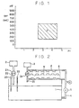
- Figure 1 shows the pH and oxidation-reduction potential ranges of the bath which is employed by this invention.
- the rectangle marked "A" in Figure 1 indicates the pH and ORP ranges defined by this invention.
- Iron and steel are the metal materials which can be treated by the method of this invention.
- the term "iron and steel” does not simply mean ordinary iron and steel, but also covers alloy steel and surface-treated steel such as galvanized steel plate.
- the concentration control of the bath can be effected automatically in accordance with the results of measurement of its pH and ORP, as the film forming reaction proceeds electrochemically. If steel is placed in the bath, its principal component (H 2 PO 4 ⁇ , Zn 2+ and NO 2 ⁇ forming a coordinate bond with Zn 2+ ) reacts with the steel and is removed from the bath by forming a coating on the steel.
- the pH and ORP of the bath are correlated to.the concentration of the principal component.
- valve for supplying the principal component so that it may, for example, open when the pH of the bath has risen above 3.2 and close when it has dropped below 3.2.
- auxiliary component alkali
- the supply of the auxiliary component can likewise be controlled. It is, for example, effective to adapt a valve for supplying it so that it may open when the oxidation-reduction potential of the bath has risen above 430 mV and close when it has dropped below 430 mV. Both of the pH and ORP are very easy to determine electrically without requiring any chemical analysis. It is, therefore, easy to realize the automatic control of the bath.
- Examples of the bath are a bath containing the principal component A [3800 mg/l of Zn 2+ , 10,000 mg/i of H 2 PO 4 -, 2600 mg/l of NO 3 - (containing NO 2 - forming a coordinate bond), 10 to 15 mg/l of Ni 2+ , etc.] and having a pH range of 3.0 to 3.4, and a bath containing the principal compoennt B [1600 mg/i of Zn 2+ , 4800 mg/l of H 2 PO 4 - , 960 mg/1 of NO 3 - (containing NO 2 - forming a coordinate bond), 4 to 5 mg/I of Ni 2+ , etc. and having a pH range of 3.8 to 4.1.
- the auxiliary component may be an aqueous solution containing 1 to 10% by weight of sodium hydroxide (NaOH) and added to the bath containing the principal component A or B.
- the phosphate coating obtained by the method of this invention is higher in density than the coating formed by the conventional method.
- the higher density means the improved corrosion resistance of the paint applied to the coating and the improved stretchability of the coating during, for example, cold forming.
- the excellent coating owes itself to a reason which can be explained by the experience relating to the electrochemical reaction taking place on the metal surface which is, for example, plated. It is known from experience that an increase in the overvoltage of the metal (electrode) surface gives a higher density and a higher stability to the electrodeposit (coating) formed thereon if the anions in the solution are of the same composition and concentration.
- the method of this invention is superior to the conventional method not only in the density and stability of the phosphate coating which it forms, but also in the ease of bath control and even its automatic control, since it enables the bath control based on the measurement of its pH and oxidation-reduction potential. Moreover, it employs a bath at an ambient temperature not exceeding 40°C and does not require the heating of the bath, as opposed to the conventional method. This means a reduction in the consumption of energy. Moreover, it enables a reduction in the self-decomposition of the bath components and thereby the efficient use thereof. It reduces to a half or less the quantity of the bath components which has hitherto been required. This enables a drastic reduction in the sludge formed in the bath. The method of this invention can be carried out by a simpler apparatus, as it does not require any settling tank that has been essential for the conventional bath.
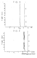
- a principal component supply pipe 22 extending from a principal component tank 2 and having a solenoid valve 21 and an auxiliary component supply pipe 25 extending from an auxiliary component tank 3 and having a solenoid valve 24 were connected to a treatment tank 1 holding 0.8 m 3 of a bath containing 3800 mg/I of zinc ions, 10,000 mg/I of phosphoric acid ions, 2600 mg/I of nitric acid ions (containing N0 2 - forming a coordinate bond) and 10 to 15 mg/I of nickel, as shown schematically in Figure 3.
- the solenoid valves 21 and 24 were electrically connected to each other by an electric circuit (not shown) adapted for opening or closing by a pH meter 23 and an oxidation-reduction potential meter 33, which were immersed in the bath, so that the valve 21 might open to supply the principal component from the tank 2 to the tank 1 with an increase in the pH of the bath to 3.2 or above and close with a drop in the pH of the bath to 3.2 or below, and so that the valve 24 might open and supply the auxiliary component from the tank 3 to the tank 1 with a drop in the pH of the bath to below 3.2 and close with its rise to 3.2 or above.
- the solenoid valve 24 was also adapted to open and supply the auxiliary component from the tank 3 to the tank 1 if the oxidation-reductin potential meter (silver chloride electrode, 33 indicated a potential of 230 mV or above (AgCI electrode potential), and close if it indicated a potential of 230 mV or below (AgCI electrode potential).
- a spray pipe 4 was provided on the sidewall of the tank 1 and connected through a pump 5 to two vertically spaced apart rows 6 of spray nozzles disposed above the tank 1 to spray the bath against the surface of the work-piece W.
- the principal component used for replenishing purposes was an acidic aqueous solution supplying 1.4 g of zinc, 4.0 g of phosphoric acid, 0.8 g of nitric acid and 0.05 g of nickel per minute, and the auxiliary component was an aqueous solution supplying 0.14 g of OH- per minute.
- the work-piece was a pulley for an AC generator for an automobile made by press forming cold rolled steel plate or cutting casting steel (FC-15) and having a diameter of about 6 to 9 cm.
- the work was degreased by spraying an aqueous alkali solution at 55°C for two minutes, washed in water at 45°C for 0.5 minute, washed by spraying water at an ambient temperature (20°C to 30°C) for 0.5 minute, subjected to phosphate coating treatment by spraying the bath at an ambient temperature (20°C to 30°C) for two minutes by the apparatus of Figure 3, washed by spraying water at an ambient temperature for 0.5 minute, washed by spraying water at an ambient temperature for 0.5 minute and dried by hot air at 80°C to 90°C for two minutes, whereby a phosphate coating consisting mainly of zinc phosphate was formed on the work-piece surface. Two thousand pieces of work were treated per hour by this apparatus, while the bath was controlled fully automatically. The treatment was continued for 100 days and nothing abnormal was found in the bath.
- FIG. 3 The records of automatic control of the bath are shown in Figures 3 and 4.
- a BHC-76-6045 pH electrode and an HBR-92 controlling recorder which were the_products of Denkikagaku Keiki K.K., were used for controlling the pH of the bath.
- Figure 3 is a typical representation of a part of the pH recorder.
- the abscissas denote the pH value and the ordinates denote time. The ordinates are graduated in hours.
- the area marked (c) in Figure 3 represents the records of control achieved by supplying the principal component when the pH of the bath rose to 3.2 or above and discontinuing its supply when the pH dropped to 3.2 or below.
- the pH values were always 3.2 or higher despite the constant supply of the principal component consisting of an acidic solution, because the ORP control of the bath maintained a constant supply of the auxiliary component (sodium hydroxide solution) in the bath by adding it if the pH of the bath dropped below 3.2.
- the auxiliary component sodium hydroxide solution
- the bath was used for treatment for 16 hours a day). The bath was at a temperature of 23°C to 35°C.
- the pH of the bath did not show any appreciable change irrespective of the presence of the steel to be treated therein. This is obviously due to the fact that the ions in the bath, such as Zn 2+ , HzP04' and NO z * , formed coordinate bonds with one another, as hereinbefore stated. (The ratio of N0 3 - to NO 2 ⁇ forming a coordinate bond is not clear, nor is its clarification required).
- the pH range shown at [D] in Figure 3 is of the bath in which no steel was present, and hardly differs from the range shown at [C].
- Figure 4 shows a part of the ORP recorder.
- the abscissas denote the oxidation-reduction potential and the ordinates denote time. The ordinates are graduated in hours.
- the silver chloride electrode is of the type which is widely used, and its potential is converted to the potential of a normal hydrogen electrode by formula (13): where
- pH and ORP values herein shown are those as measured at the temperature at which the bath was used, as hereinbefore stated, and do not take the temperature coefficient of formula (13) into consideration.
- the auxiliary component (alkali) was supplied to the bath when its ORP had risen to a level of 230 mV or above (AgCI electrode potential), and its supply was discontinued when the ORP had dropped to 230 mV or below (AgCl electrode potential).
- the ORP of the bath was maintained in the range of 230 ⁇ 10 mV (AgCI electrode potential).
- the stability of the potential shown at [G] was due to the interruption of supply of the material to be treated (steel). It returned to the state shown at [F] when the supply of the material was started again.
- the method of this invention enables the fully automatic electrochemical control of the bath as hereinabove described. It is, however, necessasry to prevent any electrochemical reaction between the bath and the material of the treatment tank. It is, therefore, desirable to make the tank of highly insulated construction (for example, by lining it with rubber).
- a black urethane-epoxy resin paint was sprayed onto the material on which a phosphate coating had been formed as hereinabove described.
- the paint was allowed to set for three minutes and baked for six minutes in a baking furnace having a temperature of 180°C to yield a coated film having a thickness of 8 to 12-p.
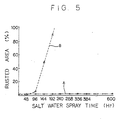
- a salt spray test was conducted in accordance with the procedure of JIS k-5400-7.8 to examine the corrosion resistance of the coated film. The results are shown in Figure 5.
- Curve A in Figure 5 shows the rusted area of the coated material treated according to the method of this invention in relation to the salt spray time.
- Curve B shows the results obtained on the coated material treated according to the conventional method.
- the material on which the phosphate coating had been formed by the method of this invention showed a drastic improvement in corrosion resistance over the material which had been treated with the conventional bath having a high temperature exceeding 40°C (i.e. having a temperature of 50°C to 55°C, a pH range of 3.1 to 3.3 and an ORP range of 730 to 750 mV, its principal component being equal in composition to that of the bath employed by the method of this invention).
Description
- This invention relates to a method of forming a chemical phosphate coating, such as of zinc phosphate, on the surface of steel.
- A chemical phosphate coating is used, for example, as an undercoat for rustproofing a steel plate or improving the adhesion of a paint thereto, or for improving the lubricating property of a frictionally slidable structural steel member. A chemical phosphate coating has hitherto been formed by employing a treatment bath having a temperature of at least 40°C and supplying it with those quantities of a principal component containing phosphoric acid ions and zinc or other metal ions and an auxiliary component containing nitrite ions which are determined by the chemical volumetric analysis of the total acid, free acid and oxidizing agent in the bath with the aid of the worker's experience. It has, however, been difficult to control the bath properly even with the aid of the worker's experience, as the chemical volumetric analysis requires a lot of time and gives rise to a certain change, which is apparently due to an abnormal reaction, in the bath. It has been difficult to always form a coating of equally good quality which is, for example, useful for rustproofing a steel plate. These problems have been due to the fact that the reaction by which a phosphate coating is formed is not clear in detail and cannot, therefore, be controlled efficiently.
- Therefore, the inventor of this invention has studied the reaction and had a new recognition as will hereinafter be set forth. As the bath has a high temperature (at least 40°C), the components therein always have the energy which activates their reaction. Even a slight change in temperature concentration, etc. affects the bath and causes the reactions between its components, such as (1) the formation of a sludge and (2) decomposition of the oxidizing agent, resulting in an unbalance between the components in the bath. This makes abnormal the reaction between the components in the bath and the steel to be treated, which is the most important reaction. In the process of chemical conversion phosphating, if the bath is held at an ambient temperature (20°C to 30°C), however, the stability of the components balance in the bath is maintained and the reaction takes place only between the bath components and the steel surface if certain conditions are satisfied. It is possible to control the reaction from an electrochemical standpoint, since the reaction occurs mainly as an electrochemical general corrosion reaction. The reaction occurs only when the steel surface contacts the bath. When the steel to be treated is not put into the bath, it remains stable and is, therefore, easy to control.
- The method of this invention is characterized by the features in
claim 1. A treatment bath is used having no oxidizing agent such as nitrite ions or hydrogen peroxide, and which maintains its temperature in a range not exceeding 40°C, its pH in the range of 2.5 to 4.5 and its oxidation-reduction potential (ORP in terms of the normal hydrogen electrode potential unless otherwise noted) in the range of 150 to 550 mV. The bath is formed from two components (agents) as will hereinafter be described. The first component is an acidic solution consisting mainly of H2P04-, (H3P04), and oxo acid ions, such as N03-, and metal ions, such as Zn2+. It will hereinafter be called the principal component. The second component is an alkaline solution containing hydroxide ions (OH-) and will hereinafter be called the auxiliary component. The bath is an aqueous solution of the principal and auxiliary components. According to this invention, the bath preferably has a temperature of 20°C to 30°C, a pH value of 3.0 to 4.0 and an ORP of 350 to 450 mV. - According to this invention, no oxidizing agent, such as nitrite ions (N02-), is used to prepare the bath or maintain its concentration, as opposed to the conventional method. This is an important feature of this invention. The term "oxidizing agent such as N02 as herein used means an agent which reacts very actively if added directly to the principal component, and exhibits so strong an oxidizing action that it cannot retain for a long time (at least an hour) the chemical formula representing it prior to its mixture with the principal component. Therefore, the oxo acid (e.g. N03-) which can be mixed with the principal component beforehand is not an oxidizing agent in the context of this invention.
- The zinc ions are not the only metal ions that the principal component can contain. It is equally possible to use manganese, calcium, magnesium or other metal which forms a hydrogenphosphate which is stable in an aqueous solution, and which shows a great reduction in solubility as a result of dehydrogenation as represented by formula (1):

- According to this invention, the bath may further contain in its principal component nickel or like metal ions, other than zinc ions, as is usually the case with the bath employed by the conventional method.
- The negative oxo acid ions which the principal component contains, such as N03- and ClO3―, serve to dissolve the film-forming constituents, such as H2PO4 - and Zn2-, in water in the bath and also promote a cathode reaction in the electrochemical reaction on the metal surface to thereby assist the formation of a coated film. The constituents of the auxiliary component undergo an electrochemical reaction with the oxo acid ions in the principal component to assist the formation of a coated film by the principal component.
- This invention is characterized by the electrochemical general corrosion reaction which takes place on the steel surface to form a phosphate coating thereon. The electrochemical general corrosion reaction is featured by the simultaneous occurrence on the metal surface of an anode reaction (oxidizing reaction such as the melting of the metal) and a cathode reaction (reducing reaction). This reaction enables the uniform erosion (dissolving) of steel and the product of corrosion forms a uniform film on the steel surface to inhibit any further dissolving of the steel when the composition of the negative ions, the concentration of components and other conditions are appropriately selected.
- In case the oxo acid ions, the principal component, are N03-, the anode reaction in the general corrosion reaction on the surface of steel is represented by formulas (2) to (4)


- Although no NO2- is supplied to the bath, the cathode reaction employs the NO2- which is formed by the electrochemical reaction of N03-, as shown by formulas (6) and (7), when the auxiliary component (alkali) is added to the bath. The potential (V) shown for each of reactions (2), (5), (6) and (7) is the potential of a normal hydrogen electrode (NHE).


- If the pH of the bath is maintained in the range of 2.5 to 4.5 and its ORP in the range of 150 to 550 mV, the reactions of formulas (6) and (7) take place electrochemically to form the N02 required for causing the reaction of formula (5) in the bath only when the auxiliary component is added to the bath. It is in a very small quantity (10 ppm or less) that the NO2- ions formed by the reactions of formulas (6) and (7) stay free in the bath. This is obvious from the fact that no N2 gas indicating the presence of free NO2- is detected by a method which is widely employed for measuring the concentration of free N02 by using sulfamic acid. Therefore, the NO2- ions formed by reactions (6) and (7) are believed to exist in the bath in a state other than free (i.e., forming a coordinate bond with metal ions).
- The chemical reaction proceeds in a direction which brings about a reduction in the Gibbs free energy (AG) of the whole reaction system.
- Formulas (2) to (5) can be regarded as defining an electrochemical reaction system for forming a phosphate coating on the metal surface.
- If the AG of the reaction system is reduced at an ambient temperature, it is possible to form a coating without applying any heat.
- It has hitherto been impossible to have the phosphate coating forming reaction take place at an ambient temperature, since it has been impossible to control properly the reaction system defined by formulas (2) to (5). This invention enables the formation of a phosphate coating on the steel surface at an ambient temperature by controlling the reaction, which is basically understood as an electrochemical reaction defined by formulas (2) to (5), in such a way that the reaction system may not contain any reaction inhibitor, such as sludge Zn3(PO4)2.
- Thus, this invention has, among others, the following three advantages:
- (1) It enables the formation of a phosphate coating at an ambient temperature (not exceeding 40°C);
- (2) It enables the automatic control of the reaction for forming a phosphate coating; and
- (3) It enables the reaction, though no oxidizing agent, such as NO2-, is directly added to the bath.
- The method of this invention employs a bath temperature of 0°C to 40°C for suppressing the nonelectrochemical (thermal) reaction which takes place in the bath according to the conventional method, and causing the electrochemical general corrosion reaction to form a chemical coating. The use of a high bath temperature, as by the conventional method, facilitates the progress of thermal decomposition reaction. When thermal energy has been supplied from an external source to a reaction system, the resulting chemical reaction is usually endothermic and increases the entropy (AS) of the reaction system.
- This results in a thermal decomposition reaction which forms hydrogen ions (H+) and electrons (e) in the bath. The high temperature of the bath does not permit the hydrogen ions and electrons to exist separately from each other. It is, therefore, difficult to control electrochemically the reaction in a bath heated to a temperature of at least 40°C.
- In addition to the electrochemical reactions of formulas (2) to (5), the thermal decomposition reactions of formulas (8) and (9) are considered to proceed actively in a hot phosphate treatment bath:


- In the hot bath, therefore, the reaction of formula (8) consumes nitrite ions and produces N02 gas and the reaction of formula (10) produces H2 gas. The reaction of formula (11) produces sludge Zn3(PO4)2. The components of the hot bath decompose themselves under heat and are consumed to form N02 gas, H2 gas and sludge. An additional supply of the components is, therefore, required for the bath to form a phosphate coating.
- The method of this invention makes it possible to inhibit the reactions of formulas (8) and (9), since the bath has a temperature not exceeding 40°C and no oxidizing agent (free N02 is directly added to the bath. This enables the presence of stable positive and negative ions in the bath. It is further possible to suppress the reactions of formulas (10) and (11) and thereby reduce the generation of H2 gas and sludge greatly.
- The method of this invention thus, restricts the inhibiting reactions and the formation of the inhibiting substances and permits the reactions of formulas (2) to (5) to take place only when the steel to be treated has been placed in the bath, thereby enabling them to proceed efficiently at an ambient temperature.
-
- Fig. 1 is a graph showing the pH and oxidation-reduction potential ranges of the bath according to this invention, Fig. 2 is a schematic view of the apparatus used for carrying out this invention, Fig. 3 is a chart showing the record of the pH value obtained as a result of automatic control according to the method of this invention, Fig. 4 is a chart showing the record of the ORP value obtained as a result of automatic control according to the method of this invention, and Fig. 5 is a graph comparing the materials treated by the method of this invention and by the conventional method with respect to the rusted area in relation to the salt water spray time.
- In order to enable the use of an ordinary production line for the phosphate coating forming reaction at an ambient temperature, it is necessary to employ a sufficiently high reaction rate. The factors affecting the rate of a chemical reaction at an electrode are (a) a sufficiently high concentration of the substances to be reacted, (b) a sufficiently low concentration of the substances inhibiting the reaction, (c) temperature, (d) pressure and (e) electrode potential. Although an increase in temperature accelerates the reaction, it is necessary to employ a low temperature in order to prevent the generation of gases inhibiting the reaction as shown by formulas (8), (10) and (11). In case treatment is effected by dipping, the pressure is usually maintained at an atmospheric level, but in the case of treatment by spraying, it is preferable to employ a somewhat higher pressure. As regards the concentration of the reaction substance for the dissolving reaction of iron represented by formula (2), it is preferable to employ both the oxidizing agent, such as N02 , and the hydrogen ions-at high concentrations, but for the film forming reaction of formulas (3) and (4), it is necessary to maintain the concentration of hydrogen ions at or below a certain level. As regards the electrode potential, it is necessary to ensure at least that the potential of reaction of the oxidizing agent (potential of the cathode reaction) be higher than the potential of dissolving reaction of steel (anode potential).
- It follows that in order to cause the reaction for forming a phosphate coating on the steel surface to proceed electrochemically at a specific rate at a temperature of 0°C to 40°C, it is necessary to:
- (a) employ a combination of the material which dissolves at a sufficiently high speed at the ambient temperature and the bath; and
- (b) maintain the concentrations of the film forming agent, oxidizing agent, hydrogen ions and other reactants in the bath in a range enabling the formation of a phosphate film at the ambient temperature.
- In case the material to be treated is steel, the requirement (a) is satisfied by a bath containing phosporic acid ions, nitrate ions, zinc ions and the others as its principal component and an alkali, e.g. caustic soda, as its auxiliary component and having a pH range of 2.5 to 4.5 and an ORP range of 150 to 550 mV. The requirement (b) is satisfied by a bath (1) containing at least 2 g of phosphoric acid ions per liter, (2) having a sufficiently low sludge content and (3) having a pH range of 2.5 to 4.5 and an ORP range of 150 to 550 mV.
- The addition of the auxiliary component containing OH-, which is one of the salient features of this invention, is necessary for converting N03- to N02 in the bath. Insofar as a bath having an ambient temperature is hardly affected by thermal energy, it is more necessary to keep a proper balance of its components than in a high temperature bath. More specifically, it is necessary to keep a certain balance in the concentrations of H2PO4― , NO3―, Zn2+, NO2― , sludge Zn3(P04)2, etc. in the bath. The H2P04- and Zn2+ show a positive decrease with the formation of a film. This means a relative increase in NO3- if the bath is used continuously at an ambient temperature. It is well known from experience that N03 - interferes with the film forming reaction. It is, therefore, necessary to remove N03 - from the bath by some method or other in order to keep a proper balance of the components in the bath. It is evident from basic chemistry that the increase in NO3- alone raises the ORP of the bath and lowers its pH. According to this invention, the bath has an ORP range of 150 to 550 mV. If its ORP has increased, the auxiliary component (alkali) is added to the bath so that the anode reaction of formula (6) may take place to lower its ORP.
- According to this invention, the bath has a pH range of 2.5 to 4.5. If the pH of the bath has exceeded a particular level between 2.5 and 4.5, the principal component, which is an acidic solution, is added to the bath, and if it has dropped below that level, the auxiliary component (alkali) is added to the bath, so that its pH may be maintained within the specific range. (The addition of the principal component raises the ORP of the bath). The reaction of formula (6) is an anode reaction, while that of formula (7) is a cathode reaction, and the N03 - ions in the bath are thereby converted to NO2― . The NO2― ions are a strong "ligand" according to the chemistry of complex salts. As they form a coordinate bond with metal ions in the bath, its ORP and pH are both stable (free from any substantial fluctuation). The bath at an ambient temperature (not exceeding 40°C) is, therefore, stable. The reaction of formula (7), etc. removes N03 from a bath having a high temperature (40°C or above), as from a bath at an ambient temperature. This is, however, not as a result of electrochemical reaction, but mainly due to a reduction in the heat content (AH) of the reaction system. The alkali which can be used as the auxiliary component is not only sodium or potassium hydroxide, but also sodium carbonate or any other salt that forms an alkaline aqueous solution. It is also possible to use ZnO2 2―. The appropriate addition of the alkali to the bath causes the removal of N03- therefrom with the addition of OH- as shown by formulas (6) and (7). The excessive addition of OH-, however, results not only in the removal of N03-, but also in the reaction of OH- with H2PO4― forming sludge as shown by the following formula:

- The pH and ORP of the bath change in accordance with formula (12). Its pH increases and its ORP decreases, whereby the sludge is formed in the bath and inhibits the formation of a film. According to the method of this invention, however, the supply of the principal agent (acidic solution) and the auxiliary component (alkali) is controlled automatically in accordance with pH and ORP control as hereinabove described. Therefore, no sludge is formed in the bath, but it is maintained in proper conditions for forming a coating on the steel surface.
- The method disclosed in a prior patent application JP-A-152150/1983) enables the film forming reaction even in the presence of a large amount of sludge. It, however, involves the addition of free NO2― to the bath and differs from the method of this invention which does not involve the addition of free NO2―. A similar prior art is known from Patent Abstracts of Japan, Vol. 7, no. 263 (c-196) [1408], 24th Nov. 83.
- The method of this invention employs a wider pH range, though a narrower ORP range, than that of JP-A-152150/1983. A brief discussion of these differences will hereinafter be made. The narrower ORP range is due to the fact that the method of this invention does not use free NO2― . The ORP of the bath is affected more easily by the pressence of free radicals than by any other factor. According to the method of this invention, the bath hardly contains any free NO2― and its ORP can, therefore, be kept in a low and narrow range. This invention enables a higher and wider pH range than the method of JP-A-152150/ 1983. This is also due to the absence of free N02- in the bath. In a pH range of 3.5 and above, the solubility of the 'phosphoric acid-zinc compound' shows not a small reduction resulting in a relative increase of the sludge of zinc phosphate [Zn3(PO4)2] (and still more at a high temperature). At an ambient temperature and if N02 forms a coordinate bond with metal, however, metal (mainly zinc) ions, dihydrogenphosphate ions (H2PO4―) and NO2― form a complex salt having a higher degree of solubility. It is, therefore, possible to prepare a bath containing a relatively large quantity of H2PO4― and Zn2+ which are reactive even at a pH level of 3.5 or above. Although the method of JP-A-152150/1983 is also carried out at an ambient temperature, the addition of free N02- to the bath results in the formation of a large amount of sludge in the bath, as opposed to the method of this invention, and thereby the inhibition of the film forming reaction.
- The conventional high temperature bath has usually a pH range of 3.0 to 3.4 if it is used for treatment by spraying, or a pH range of 1.0 to 3.0 if it is used for dipping treatment. According to the method of this invention, the bath temperature not exceeding 40°C makes it difficult for sludge to form in the bath and the reactions of formulas (3) and (4) take place mainly on the steel surface. This enables the bath to have a wider pH range of 2.5 to 4.5. If its pH is lower than 2.5, the film forming reactions of formulas (3) and (4) are restricted. If the temperature of a phosphate treatment bath is lowered when its pH and ORP are measured, a change occurs to the equilibrium reactions in the bath, as is obvious from, for example, an increase in 'free acid concentration'. This change gives the results of measurement which differ from what would be obtained if the temperature were not lowered. The pH and ORP values appearing in this specification are those obtained at the temperature at which the bath is used.
- The bath employed by the method of this invention has an ORP range of 150 to 550 mV. It is low as compared with the oxidation-reduction potential of about 500 mV or higher of the bath which has hitherto been used at a high temperature. The high ORP of the conventional bath is apparently due to the synergism of two factors, i.e., that the self-decomposition of the bath components is promoted by heat and necessitates the constant supply of a large amount of oxidizing agent in addition to the principal component such as phosphoric acid, and that the bath is held at a high temperature. It is also true that the presence of a large amount of sludge of zinc phosphate, from which the coating is also formed, makes it necessary to provide a large force for promoting the film forming reaction on the steel surface. It is, therefore, necessary to heat the bath and add a large amount of oxidizing agent, such as free NO2― , as well as the principal component (acidic solution), to promote the reaction. These factors raise the ORP of the bath.
- According to the method of this invention, it is possible to promote the electrochemical film-forming reaction with an ideally high degree of efficiency in a wider pH range and a lower oxidation-reduction potential range (not exceeding 550 mV) than those of the conventional bath, since the bath is substantially free from any sludge and has a low temperature, and since no oxidizing agent, such as N02-, is added directly to the bath.
- Figure 1 shows the pH and oxidation-reduction potential ranges of the bath which is employed by this invention. The rectangle marked "A" in Figure 1 indicates the pH and ORP ranges defined by this invention.
- Iron and steel are the metal materials which can be treated by the method of this invention. The term "iron and steel" does not simply mean ordinary iron and steel, but also covers alloy steel and surface-treated steel such as galvanized steel plate. According to the method of this invention, the concentration control of the bath can be effected automatically in accordance with the results of measurement of its pH and ORP, as the film forming reaction proceeds electrochemically. If steel is placed in the bath, its principal component (H2PO4― , Zn2+ and NO2― forming a coordinate bond with Zn2+) reacts with the steel and is removed from the bath by forming a coating on the steel. The pH and ORP of the bath are correlated to.the concentration of the principal component. As the H2PO4― and Zn2+ in the principal component are consumed for the film forming reaction, the bath now contains a relatively large amount of NO3―. Accordingly, the pH of the bath decreases and its ORP increases. If the auxiliary component (alkali) is added to the bath, the reactions of formulas (6) and (7) take place to convert NO3- to NO2- (NO2- forming a coordinate bond) to thereby raise the pH of the bath and lower its ORP.
- Thus, it is convenient to adapt a valve for supplying the principal component so that it may, for example, open when the pH of the bath has risen above 3.2 and close when it has dropped below 3.2. (It is also effective to add the auxiliary component (alkali) to the bath when its pH has dropped).
- The supply of the auxiliary component can likewise be controlled. It is, for example, effective to adapt a valve for supplying it so that it may open when the oxidation-reduction potential of the bath has risen above 430 mV and close when it has dropped below 430 mV. Both of the pH and ORP are very easy to determine electrically without requiring any chemical analysis. It is, therefore, easy to realize the automatic control of the bath. Examples of the bath are a bath containing the principal component A [3800 mg/l of Zn2+, 10,000 mg/i of H2PO4-, 2600 mg/l of NO3- (containing NO2- forming a coordinate bond), 10 to 15 mg/l of Ni2+, etc.] and having a pH range of 3.0 to 3.4, and a bath containing the principal compoennt B [1600 mg/i of Zn2+, 4800 mg/l of H2PO4- , 960 mg/1 of NO3- (containing NO2- forming a coordinate bond), 4 to 5 mg/I of Ni2+, etc. and having a pH range of 3.8 to 4.1.
- When the principal component is supplied to the bath, it is appropriate to supply a concentrated solution having a concentration which is 10 to 40 times higher than what has hereinabove been set forth. The auxiliary component may be an aqueous solution containing 1 to 10% by weight of sodium hydroxide (NaOH) and added to the bath containing the principal component A or B.
- The phosphate coating obtained by the method of this invention is higher in density than the coating formed by the conventional method. The higher density means the improved corrosion resistance of the paint applied to the coating and the improved stretchability of the coating during, for example, cold forming. The excellent coating owes itself to a reason which can be explained by the experience relating to the electrochemical reaction taking place on the metal surface which is, for example, plated. It is known from experience that an increase in the overvoltage of the metal (electrode) surface gives a higher density and a higher stability to the electrodeposit (coating) formed thereon if the anions in the solution are of the same composition and concentration. It is also known that the overvoltage of the metal surface shows a sharp reduction with a rise in temperature and that a rise in temperature results in a less stable coating having a coarser crystal structure. These facts are believed to explain the high density and stability of the coating obtained by the method of this invention which employs a lower bath temperature than the conventional method and, therefore, forms the coating on the metal surface having a high overvoltage.
- The method of this invention is superior to the conventional method not only in the density and stability of the phosphate coating which it forms, but also in the ease of bath control and even its automatic control, since it enables the bath control based on the measurement of its pH and oxidation-reduction potential. Moreover, it employs a bath at an ambient temperature not exceeding 40°C and does not require the heating of the bath, as opposed to the conventional method. This means a reduction in the consumption of energy. Moreover, it enables a reduction in the self-decomposition of the bath components and thereby the efficient use thereof. It reduces to a half or less the quantity of the bath components which has hitherto been required. This enables a drastic reduction in the sludge formed in the bath. The method of this invention can be carried out by a simpler apparatus, as it does not require any settling tank that has been essential for the conventional bath.
- The invention will now be described by way of example.
- A principal
component supply pipe 22 extending from aprincipal component tank 2 and having asolenoid valve 21 and an auxiliarycomponent supply pipe 25 extending from anauxiliary component tank 3 and having asolenoid valve 24 were connected to atreatment tank 1 holding 0.8 m3 of a bath containing 3800 mg/I of zinc ions, 10,000 mg/I of phosphoric acid ions, 2600 mg/I of nitric acid ions (containing N02- forming a coordinate bond) and 10 to 15 mg/I of nickel, as shown schematically in Figure 3. Thesolenoid valves pH meter 23 and an oxidation-reductionpotential meter 33, which were immersed in the bath, so that thevalve 21 might open to supply the principal component from thetank 2 to thetank 1 with an increase in the pH of the bath to 3.2 or above and close with a drop in the pH of the bath to 3.2 or below, and so that thevalve 24 might open and supply the auxiliary component from thetank 3 to thetank 1 with a drop in the pH of the bath to below 3.2 and close with its rise to 3.2 or above. Thesolenoid valve 24 was also adapted to open and supply the auxiliary component from thetank 3 to thetank 1 if the oxidation-reductin potential meter (silver chloride electrode, 33 indicated a potential of 230 mV or above (AgCI electrode potential), and close if it indicated a potential of 230 mV or below (AgCI electrode potential). Aspray pipe 4 was provided on the sidewall of thetank 1 and connected through apump 5 to two vertically spaced apartrows 6 of spray nozzles disposed above thetank 1 to spray the bath against the surface of the work-piece W. The principal component used for replenishing purposes was an acidic aqueous solution supplying 1.4 g of zinc, 4.0 g of phosphoric acid, 0.8 g of nitric acid and 0.05 g of nickel per minute, and the auxiliary component was an aqueous solution supplying 0.14 g of OH- per minute. The work-piece was a pulley for an AC generator for an automobile made by press forming cold rolled steel plate or cutting casting steel (FC-15) and having a diameter of about 6 to 9 cm. - The work was degreased by spraying an aqueous alkali solution at 55°C for two minutes, washed in water at 45°C for 0.5 minute, washed by spraying water at an ambient temperature (20°C to 30°C) for 0.5 minute, subjected to phosphate coating treatment by spraying the bath at an ambient temperature (20°C to 30°C) for two minutes by the apparatus of Figure 3, washed by spraying water at an ambient temperature for 0.5 minute, washed by spraying water at an ambient temperature for 0.5 minute and dried by hot air at 80°C to 90°C for two minutes, whereby a phosphate coating consisting mainly of zinc phosphate was formed on the work-piece surface. Two thousand pieces of work were treated per hour by this apparatus, while the bath was controlled fully automatically. The treatment was continued for 100 days and nothing abnormal was found in the bath.
- The records of automatic control of the bath are shown in Figures 3 and 4. A BHC-76-6045 pH electrode and an HBR-92 controlling recorder, which were the_products of Denkikagaku Keiki K.K., were used for controlling the pH of the bath. Figure 3 is a typical representation of a part of the pH recorder. In Figure 3, the abscissas denote the pH value and the ordinates denote time. The ordinates are graduated in hours. The area marked (c) in Figure 3 represents the records of control achieved by supplying the principal component when the pH of the bath rose to 3.2 or above and discontinuing its supply when the pH dropped to 3.2 or below. The pH values were always 3.2 or higher despite the constant supply of the principal component consisting of an acidic solution, because the ORP control of the bath maintained a constant supply of the auxiliary component (sodium hydroxide solution) in the bath by adding it if the pH of the bath dropped below 3.2. Although a constant supply of the principal component was maintained for the bath, its pH remained unchanged as shown in Figure 3 and its composition also remained unchanged as shown in Table 1 below. (The bath was used for treatment for 16 hours a day). The bath was at a temperature of 23°C to 35°C.


- The pH of the bath did not show any appreciable change irrespective of the presence of the steel to be treated therein. This is obviously due to the fact that the ions in the bath, such as Zn2+, HzP04' and NOz *, formed coordinate bonds with one another, as hereinbefore stated. (The ratio of N03- to NO2― forming a coordinate bond is not clear, nor is its clarification required). The pH range shown at [D] in Figure 3 is of the bath in which no steel was present, and hardly differs from the range shown at [C].
- Figure 4 shows a part of the ORP recorder. The abscissas denote the oxidation-reduction potential and the ordinates denote time. The ordinates are graduated in hours. A BHC-76-6026 metal electrode (silver chloride electrode) and an HBR-94 controlling recorder, which were the products of Denkikagaku Keiki K.K., were used for controlling the ORP. The silver chloride electrode is of the type which is widely used, and its potential is converted to the potential of a normal hydrogen electrode by formula (13):

- E(NHE): Potential of a normal hydrogen electrode
- E(AgCI): 3.33 MKCI=Potential of AgCI electrode
- t: Temperature (°C).
- The pH and ORP values herein shown are those as measured at the temperature at which the bath was used, as hereinbefore stated, and do not take the temperature coefficient of formula (13) into consideration.
- The results shown at (E) in Figure 5 are those which were obtained during the beginning of operation before the material to be treated (steel) was placed in the bath. The ORP values of the bath were, however, only slightly higher than the results which were obtained after the material to be treated had been placed in the bath, and which are shown at [F].
- The small difference between the ORP values shown at [E] and [F] is attributable to the coordinate linkage of the ions in the bath. The coordinate linkage of NO2― and other ions prevents the ORP of the bath from rising to such a high level (700 mV or above) as it would show if they (NOz and the other) existed independently of each other. The results shown at [E] and [F] were all obtained when the supply of the auxiliary component (alkali) was automatically controlled in accordance with the ORP of the bath. More specifically, the auxiliary component (alkali) was supplied to the bath when its ORP had risen to a level of 230 mV or above (AgCI electrode potential), and its supply was discontinued when the ORP had dropped to 230 mV or below (AgCl electrode potential). As a result, the ORP of the bath was maintained in the range of 230±10 mV (AgCI electrode potential).
- The stability of the potential shown at [G] was due to the interruption of supply of the material to be treated (steel). It returned to the state shown at [F] when the supply of the material was started again. The method of this invention enables the fully automatic electrochemical control of the bath as hereinabove described. It is, however, necessasry to prevent any electrochemical reaction between the bath and the material of the treatment tank. It is, therefore, desirable to make the tank of highly insulated construction (for example, by lining it with rubber).
- A black urethane-epoxy resin paint was sprayed onto the material on which a phosphate coating had been formed as hereinabove described. The paint was allowed to set for three minutes and baked for six minutes in a baking furnace having a temperature of 180°C to yield a coated film having a thickness of 8 to 12-p. A salt spray test was conducted in accordance with the procedure of JIS k-5400-7.8 to examine the corrosion resistance of the coated film. The results are shown in Figure 5. Curve A in Figure 5 shows the rusted area of the coated material treated according to the method of this invention in relation to the salt spray time. Curve B shows the results obtained on the coated material treated according to the conventional method. The material on which the phosphate coating had been formed by the method of this invention showed a drastic improvement in corrosion resistance over the material which had been treated with the conventional bath having a high temperature exceeding 40°C (i.e. having a temperature of 50°C to 55°C, a pH range of 3.1 to 3.3 and an ORP range of 730 to 750 mV, its principal component being equal in composition to that of the bath employed by the method of this invention).
Claims (2)
Applications Claiming Priority (2)
| Application Number | Priority Date | Filing Date | Title |
|---|---|---|---|
| JP59093643A JPS60238486A (en) | 1984-05-09 | 1984-05-09 | Formation of phosphate conversion coating on steel surface |
| JP93643/84 | 1984-05-09 |
Publications (3)
| Publication Number | Publication Date |
|---|---|
| EP0162345A2 EP0162345A2 (en) | 1985-11-27 |
| EP0162345A3 EP0162345A3 (en) | 1987-12-16 |
| EP0162345B1 true EP0162345B1 (en) | 1990-04-18 |
Family
ID=14088044
Family Applications (1)
| Application Number | Title | Priority Date | Filing Date |
|---|---|---|---|
| EP85105225A Expired - Lifetime EP0162345B1 (en) | 1984-05-09 | 1985-04-29 | Method of forming a chemical phosphate coating on the surface of steel |
Country Status (5)
| Country | Link |
|---|---|
| US (1) | US4657600A (en) |
| EP (1) | EP0162345B1 (en) |
| JP (1) | JPS60238486A (en) |
| KR (1) | KR890004789B1 (en) |
| DE (1) | DE3577216D1 (en) |
Families Citing this family (7)
| Publication number | Priority date | Publication date | Assignee | Title |
|---|---|---|---|---|
| US4774145A (en) * | 1985-11-07 | 1988-09-27 | Nippondenso Co., Ltd. | Zinc phosphate chemical conversion film and method for forming the same |
| JPS63270478A (en) * | 1986-12-09 | 1988-11-08 | Nippon Denso Co Ltd | Phosphating method |
| US5236565A (en) * | 1987-04-11 | 1993-08-17 | Metallgesellschaft Aktiengesellschaft | Process of phosphating before electroimmersion painting |
| JP2739864B2 (en) * | 1991-05-01 | 1998-04-15 | 株式会社デンソー | Phosphate conversion treatment method |
| US5645706A (en) * | 1992-04-30 | 1997-07-08 | Nippondenso Co., Ltd. | Phosphate chemical treatment method |
| DE19703641B4 (en) * | 1997-01-31 | 2006-10-19 | Marx, Joachim, Dr. | Process for producing welded hollow bodies with improved corrosion protection and hollow bodies produced in this way |
| CN102094195B (en) * | 2011-01-14 | 2012-07-18 | 中国科学院宁波材料技术与工程研究所 | Phosphating method of surface of metal material |
Family Cites Families (10)
| Publication number | Priority date | Publication date | Assignee | Title |
|---|---|---|---|---|
| DE872298C (en) * | 1943-07-01 | 1953-03-30 | Metallgesellschaft Ag | Phosphating process |
| AT282285B (en) * | 1965-12-22 | 1970-06-25 | Plaut Fa J | Zinc phosphate coatings |
| US3939014A (en) * | 1974-11-20 | 1976-02-17 | Amchem Products, Inc. | Aqueous zinc phosphating solution and method of rapid coating of steel for deforming |
| AU507110B2 (en) * | 1975-04-23 | 1980-02-07 | Ici Ltd. | Phosphating process |
| JPS52141439A (en) * | 1976-04-27 | 1977-11-25 | Nippon Paint Co Ltd | Method of managing chemicallconversion treating liquid for acidic phosphate coating |
| JPS5456038A (en) * | 1977-10-12 | 1979-05-04 | Nippon Paint Co Ltd | Controlling method for acidic phosphate film forming liquid |
| JPS58144478A (en) * | 1982-02-20 | 1983-08-27 | Nippon Denso Co Ltd | Formation of chemically converted phosphate film on surface of steel |
| JPS58199874A (en) * | 1982-05-18 | 1983-11-21 | Nippon Denso Co Ltd | Formation of phosphated film on steel surface by chemical conversion treatment |
| DE3244715A1 (en) * | 1982-12-03 | 1984-06-07 | Gerhard Collardin GmbH, 5000 Köln | METHOD FOR PHOSPHATING METAL SURFACES, AND BATH SOLUTIONS SUITABLE FOR THIS |
| JPS6043491A (en) * | 1983-08-19 | 1985-03-08 | Nippon Denso Co Ltd | Formation of phosphate film on iron and steel surfaces |
-
1984
- 1984-05-09 JP JP59093643A patent/JPS60238486A/en active Granted
-
1985
- 1985-04-24 KR KR1019850002765A patent/KR890004789B1/en not_active IP Right Cessation
- 1985-04-29 DE DE8585105225T patent/DE3577216D1/en not_active Expired - Lifetime
- 1985-04-29 EP EP85105225A patent/EP0162345B1/en not_active Expired - Lifetime
- 1985-05-07 US US06/731,523 patent/US4657600A/en not_active Expired - Lifetime
Also Published As
| Publication number | Publication date |
|---|---|
| JPH0442472B2 (en) | 1992-07-13 |
| EP0162345A3 (en) | 1987-12-16 |
| JPS60238486A (en) | 1985-11-27 |
| EP0162345A2 (en) | 1985-11-27 |
| US4657600A (en) | 1987-04-14 |
| KR850008504A (en) | 1985-12-18 |
| DE3577216D1 (en) | 1990-05-23 |
| KR890004789B1 (en) | 1989-11-27 |
Similar Documents
| Publication | Publication Date | Title |
|---|---|---|
| US4565585A (en) | Method for forming a chemical conversion phosphate film on the surface of steel | |
| Abrantes et al. | On the mechanism of electroless Ni‐P plating | |
| US4927472A (en) | Conversion coating solution for treating metal surfaces | |
| JP3063920B2 (en) | How to treat metal surfaces with phosphate | |
| US4668347A (en) | Anticorrosive coated rectifier metals and their alloys | |
| CA1183430A (en) | Process for the phosphatising of metals | |
| US4717431A (en) | Nickel-free metal phosphating composition and method for use | |
| RU2510431C2 (en) | Liquid for chemical conversion treatment of metallic material and treatment method | |
| US4824490A (en) | Process of producing phosphate coatings on metals | |
| EP0162345B1 (en) | Method of forming a chemical phosphate coating on the surface of steel | |
| US4363708A (en) | Process for exposing silicon crystals on the surface of a component of an aluminum alloy of high silicon content | |
| JPH041073B2 (en) | ||
| US2326309A (en) | Method of producing phosphate coatings on ferrous metal articles | |
| US4089710A (en) | Phosphating method with control in response to conductivity change | |
| US3333988A (en) | Phosphate coating process | |
| WO1995027809A1 (en) | Method of pre-treating metal substrates prior to painting | |
| US4086103A (en) | Accelerator for phosphating solutions | |
| US4443273A (en) | Method for replenishing chemical in zinc phosphate treatment | |
| KR900000302B1 (en) | Method for forming a chemical conversion phosphate film on the surface of steel | |
| CA2236512C (en) | Process of phosphatizing metal surfaces | |
| US4774145A (en) | Zinc phosphate chemical conversion film and method for forming the same | |
| JP3256009B2 (en) | Tinplate surface treatment liquid and surface treatment method | |
| US4071379A (en) | Phosphating method | |
| KR930007924B1 (en) | Conversion coating compound in normal temperature | |
| JPH0411630B2 (en) |
Legal Events
| Date | Code | Title | Description |
|---|---|---|---|
| PUAI | Public reference made under article 153(3) epc to a published international application that has entered the european phase |
Free format text: ORIGINAL CODE: 0009012 |
|
| AK | Designated contracting states |
Designated state(s): DE FR GB IT |
|
| PUAL | Search report despatched |
Free format text: ORIGINAL CODE: 0009013 |
|
| AK | Designated contracting states |
Kind code of ref document: A3 Designated state(s): DE FR GB IT |
|
| 17P | Request for examination filed |
Effective date: 19871211 |
|
| 17Q | First examination report despatched |
Effective date: 19890216 |
|
| GRAA | (expected) grant |
Free format text: ORIGINAL CODE: 0009210 |
|
| AK | Designated contracting states |
Kind code of ref document: B1 Designated state(s): DE FR GB IT |
|
| REF | Corresponds to: |
Ref document number: 3577216 Country of ref document: DE Date of ref document: 19900523 |
|
| ITF | It: translation for a ep patent filed |
Owner name: DR. ING. A. RACHELI & C. |
|
| ET | Fr: translation filed | ||
| REG | Reference to a national code |
Ref country code: GB Ref legal event code: 746 |
|
| PLBE | No opposition filed within time limit |
Free format text: ORIGINAL CODE: 0009261 |
|
| STAA | Information on the status of an ep patent application or granted ep patent |
Free format text: STATUS: NO OPPOSITION FILED WITHIN TIME LIMIT |
|
| ITPR | It: changes in ownership of a european patent |
Owner name: OFFERTA DI LICENZA AL PUBBLICO |
|
| 26N | No opposition filed | ||
| ITTA | It: last paid annual fee | ||
| REG | Reference to a national code |
Ref country code: FR Ref legal event code: DL |
|
| PGFP | Annual fee paid to national office [announced via postgrant information from national office to epo] |
Ref country code: FR Payment date: 20010409 Year of fee payment: 17 |
|
| PGFP | Annual fee paid to national office [announced via postgrant information from national office to epo] |
Ref country code: DE Payment date: 20010423 Year of fee payment: 17 |
|
| PGFP | Annual fee paid to national office [announced via postgrant information from national office to epo] |
Ref country code: GB Payment date: 20010425 Year of fee payment: 17 |
|
| REG | Reference to a national code |
Ref country code: GB Ref legal event code: IF02 |
|
| PG25 | Lapsed in a contracting state [announced via postgrant information from national office to epo] |
Ref country code: GB Free format text: LAPSE BECAUSE OF NON-PAYMENT OF DUE FEES Effective date: 20020429 |
|
| PG25 | Lapsed in a contracting state [announced via postgrant information from national office to epo] |
Ref country code: DE Free format text: LAPSE BECAUSE OF NON-PAYMENT OF DUE FEES Effective date: 20021101 |
|
| GBPC | Gb: european patent ceased through non-payment of renewal fee |
Effective date: 20020429 |
|
| PG25 | Lapsed in a contracting state [announced via postgrant information from national office to epo] |
Ref country code: FR Free format text: LAPSE BECAUSE OF NON-PAYMENT OF DUE FEES Effective date: 20021231 |
|
| REG | Reference to a national code |
Ref country code: FR Ref legal event code: ST |