EP0162073B1 - Introduction of samples into a mass spectrometer - Google Patents
Introduction of samples into a mass spectrometer Download PDFInfo
- Publication number
- EP0162073B1 EP0162073B1 EP84904152A EP84904152A EP0162073B1 EP 0162073 B1 EP0162073 B1 EP 0162073B1 EP 84904152 A EP84904152 A EP 84904152A EP 84904152 A EP84904152 A EP 84904152A EP 0162073 B1 EP0162073 B1 EP 0162073B1
- Authority
- EP
- European Patent Office
- Prior art keywords
- magazine
- sample
- tube
- movement
- mass spectrometer
- Prior art date
- Legal status (The legal status is an assumption and is not a legal conclusion. Google has not performed a legal analysis and makes no representation as to the accuracy of the status listed.)
- Expired
Links
- 238000004458 analytical method Methods 0.000 claims abstract description 19
- 230000000284 resting effect Effects 0.000 claims description 6
- 239000002184 metal Substances 0.000 description 3
- 238000001228 spectrum Methods 0.000 description 3
- 238000010276 construction Methods 0.000 description 2
- 238000000034 method Methods 0.000 description 2
- 238000004891 communication Methods 0.000 description 1
- 230000008878 coupling Effects 0.000 description 1
- 238000010168 coupling process Methods 0.000 description 1
- 238000005859 coupling reaction Methods 0.000 description 1
- CVSVTCORWBXHQV-UHFFFAOYSA-N creatine Chemical compound NC(=[NH2+])N(C)CC([O-])=O CVSVTCORWBXHQV-UHFFFAOYSA-N 0.000 description 1
- 238000006073 displacement reaction Methods 0.000 description 1
- 230000000694 effects Effects 0.000 description 1
- 239000013013 elastic material Substances 0.000 description 1
- 238000010438 heat treatment Methods 0.000 description 1
- 230000006698 induction Effects 0.000 description 1
- 238000004949 mass spectrometry Methods 0.000 description 1
- 238000004806 packaging method and process Methods 0.000 description 1
- 238000000197 pyrolysis Methods 0.000 description 1
- 238000003908 quality control method Methods 0.000 description 1
- 238000007789 sealing Methods 0.000 description 1
Images
Classifications
-
- H—ELECTRICITY
- H01—ELECTRIC ELEMENTS
- H01J—ELECTRIC DISCHARGE TUBES OR DISCHARGE LAMPS
- H01J49/00—Particle spectrometers or separator tubes
- H01J49/02—Details
- H01J49/04—Arrangements for introducing or extracting samples to be analysed, e.g. vacuum locks; Arrangements for external adjustment of electron- or ion-optical components
- H01J49/0409—Sample holders or containers
- H01J49/0413—Sample holders or containers for automated handling
-
- H—ELECTRICITY
- H01—ELECTRIC ELEMENTS
- H01J—ELECTRIC DISCHARGE TUBES OR DISCHARGE LAMPS
- H01J49/00—Particle spectrometers or separator tubes
- H01J49/02—Details
- H01J49/04—Arrangements for introducing or extracting samples to be analysed, e.g. vacuum locks; Arrangements for external adjustment of electron- or ion-optical components
- H01J49/0468—Arrangements for introducing or extracting samples to be analysed, e.g. vacuum locks; Arrangements for external adjustment of electron- or ion-optical components with means for heating or cooling the sample
- H01J49/0472—Arrangements for introducing or extracting samples to be analysed, e.g. vacuum locks; Arrangements for external adjustment of electron- or ion-optical components with means for heating or cooling the sample with means for pyrolysis
Definitions
- the present invention relates to the introduction of samples into the inlet system of a mass spectrometer.
- a sample container is offered to an aperture in the inlet system.
- the inlet system rapidly evacuates the container, pyrolyses the sample and establishes communication between the container and the vacuum chamber of the mass spectrometer to enable the sample to be analysed.
- the present invention is concerned with the feeding of samples to such an inlet system in such a manner as to take advantage of the inherent speed of operation of the mass spectrometer and enable the process of analysis to be further automated.
- a magazine for introducing samples into the inlet system of a mass spectrometer which magazine comprises a flat plate having upper and lower surfaces which are generally horizontal during use, a zig-zag groove in the lower surface engageable by a reciprocable indexing pin to advance the magazine by increments relative to an aperture of the inlet system of the mass spectrometer and recesses in the upper surface of the magazine for receiving tubes containing samples for analysis, the recesses being in the form of grooves lying substantially parallel to the plane of the plate which extend transversely to the direction of movement of the magazine and are arranged at a regular pitch equal to that of the zig-zag groove in the lower surface.
- each recess in the upper surface comprises an enlarged diameter portion for receiving an O-ring placed over the outer surface of the sample tube.
- each recess in the upper surface is formed at its end remote from the inlet system of the mass spectrometer with an enlarged diameter portion such that a pick-up tube may be slipped over the end of the sample tube while the latter is resting in the recess.
- the zig-zag groove has first portions extending parallel to the recesses in the upper surface and parallel to the direction of movement of the indexing pin such that the movement of the pin, in use, in the first portions causes no movement of the magazine, and second portions each connecting one end of a first portion with the opposite end of an adjacent first portion, the second portions being inclined relative to the direction of movement of the magazine during use and cooperating with the pin to move the magazine.
- the magazine may conveniently be packaged in combination with a plurality of tubes resting in the recesses, each fitted with an O-ring and a sample boat.
- the packaging may consist of a sealing wrapper serving to retain the sample tubes in position within the recesses. If the boats project from the sample tubes when the wrapper is opened the placing of the samples on the boats is considerably facilitated. In order to avoid accidental displacement the boats should not project beyond the edge of the magazine.
- FIG 1 there is shown at 10 part of the inlet system of the mass spectrometer.
- the inlet system 10 is not shown in detail but is preferably as described in GB-A-2,141,230.
- the inlet system 10 has an aperture 12 with a conical mouth 14 against which a tube 16 containing a sample to be analysed is sealed, the sample resting on a metal boat within the tube 16.
- the inlet system of the mass spectrometer evacuates the interior of the tube 16 and pyrolyses the sample by means of an induction coil 20 surrounding the tube 16.
- the coil 20 heats the boat in the tube 16 to a predetermined temperature (its Curie temperature) and thus pyrolyses the sample, the pyrolysate entering the vacuum chamber for analysis.
- the tube 16 is withdrawn and replaced by a new tube.
- the tubes 16, which are to contain the analysis samples, are arranged in a magazine 22 which is advanced automatically by the feed system.
- the magazine 22 has parallel recesses 24 on its top face for receiving the tubes 16.
- Each recess is in the form of a semi-cylindrical trough which is enlarged at one end (left end as viewed). Because of this enlargement 26, the end of each sample tube 16 is surrounded by a gap while resting in the recess 24 thereby enabling a pick-up tube to be slipped over the end of the sample tube 16 so that it may be picked up from the magazine 22.
- Each recess also has a further enlarged diameter portion 28 which serves to accommodate an 0-ring 30 surrounding each of the sample tubes 16.
- the magazine 22 complete with the sample tubes 16 each fitted with an 0- ring and a metal boat may be sold in sealed packages ready for the samples to be placed on the metal boats by the operator.
- the ends of the sample tubes are inset from the edge of the magazine 22 and the boats project from the sample tubes 16 but not beyond the edge of the magazine 22.
- each boat 80 is V-shaped in cross section, as shown in Figure 3, and makes contact with the tube 16 at the upper edges of its limbs but not at its base where the sample rests, the boat being wedged within the tube 16 by its own resilience.
- Such construction of the boats is also advantageous in that it reduces manufactuing costs.
- the lower side of the magazine 22 is formed with a groove 32 (shown in dotted lines in Figure 2) which is engaged by a spring biassed indexing pin 34 and acts as part of an indexing mechanism for advancing the magazine automatically, as described in more detail below.
- the groove 32 is in the form of a cpntinuous zig - zag formed of portions 32a which are parallel to and aligned with the recesses 24 and relatively inclined portions 32b connecting one end of each portion 32a with the opposite end of the adjacent portion 32a.
- the portions 32a of the groove 32 slope downwards from left to right whereas the portions 32b slope upwards from left to right.
- the indexing pin 34 is mounted on an indexing bar 36 which reciprocates from left to right in Figure 1. As the pin 34 moves to the right, as viewed, it slides along one of the portions 32a without moving the magazine 22 but is itself deflected downwards. Oh reaching the end of its travel, the pin 34 engages the end of the contiguous portion 32b and is clicked upwards into the portion 32b by its spring. When now the indexing bar 36 is retracted, the pin slides along the portion 32b and simultaneously moves the magazine to align the next sample tube 16 with the feed system and the aperture 12. Once again, on reaching the end of its travel the pin clicks into the next contiguous portion 32a of the tube.
- An advantage of the above construction of the indexing system is that the movement of the pin 34 is aligned with the inlet aperture and the portion 32a of the groove are all aligned with recesses 24.
- the movement of the magazine occurs on the return stroke of the indexing pin rather than its forward stroke.
- the pin 34 as will be described below, is moved with the mechanism feeding the tubes 16 into the inlet system 10, and as a result the tube aligned with the inlet aperture 12 when the magazine is brought to rest on the index pin 34 will be the tube first fed into the inlet system for analysis.
- the indexing bar 36 is provided on its upper surface with an elongated slot in which engages a pin 38 mounted on a carriage 40, the slot and pin 38 together constituting a lost motion coupling.
- the total stroke of the indexing bar 36 is therefore shorter than the stroke of the carriage 40 by the length of the slot in the upper surface of the indexing bar and the latter only follows the movement of the carriage at the end of the forward and return strokes.
- the carriage 40 is guided between two vertical lateral guide plates 42 of which only one is seen in Figure 1.
- the upper surface of the carriage is in the form of a rack 44 engaged by a motor driven pinion 46.
- the carriage 40 rides on rollers 48 which follow a cam track 50.
- the motor driving the pinion 46 is also mounted to move vertically with movement of the carriage 40 and is conveniently mounted on an arm pivotably supported on the outer surface of one of the guide plates 42.
- the carriage 40 has projecting from its front end a pick-up tube 52 which is split longitudinally at its forward end (the right end as viewed).
- An ejector pin 54 is received within the pick-up tube 52 at its forward end, the pin 54 having arms 56 which project laterally through the slits in the pick-up tube 52 and move in slots 58 formed in the two guide plates 42.
- a ring of an elastic material encircles the forward end of the pick-up tube 52 so that the halves of the tubes are urged resiliently towards each other.
- the feed system is shown in Figure 1 at the commencement of a feed cycle.
- the magazine 22 is positioned as earlier described such that one of the sample tubes 16 is aligned with the aperture 12.
- the motor driving the pinion 46 is now energised and moves the carriage 40 to the right, as viewed,
- the pick-up tube 52 is moved until its end engages the rear of the sample tube and grips it by virtue of the resilience of the surrounding band.
- the rollers 48 ride on the cam track ramps and raise the carriage while the sample tube 16 is maintained horizontal.
- the arms 56 of the ejector pin at this time are aligned with the ends of the slots 58 and move up the vertical section of the slots.
- the ejector pin 54 is retracted down the pick-up tube 52.
- the ramps on the cam track 50 are dimensioned to raise the sample tube to the level of the aperture 12 of the inlet system of the mass spectrometer.
- the carriage 40 continues to move forward until first the end of the sample tube 16 abuts the conical surface 14.
- the pick-up tube 52 engages the 0-ring 30 and slides it over the outer surface of the sample tube 16.
- the 0-ring 30 abuts the conical surface 14 it is compressed by the pick-up tube 52 and forms a seal.
- the motor remains energised even after a seal is made to keep a constant pressure on the 0-ring 30.
- the mass spectrometer now evacuates the sample tube 16 and performs its analysis. After the analysis is complete, the motor driving the pinion 46 is reversed and the carriage 40 moves back towards its illustrated retracted positions.
- the vacuum seal is first broken by the inlet system so that the sample tube 16 may move freely with the pick-up tube 52.
- the ejector pin 54 is prevented from moving with it by abutment of its arms with the slots 58.
- the pin 54 thus forms a stop limiting the movement of the sample tube 16 and after it has been pulled clear of the coil 20 it drops back into its own recess 24 in the magazine 22. It is noted that the magazine 22 has still not been moved until this point in the cycle.
- the carriage 40 now rides down the ramps of the cam track 50 so that the arms of the ejector pin 54 are freed by the slots 58 and ejector pin moves back with the tube 52.
- the pin 38 at this stage abuts the rear end of the slot in the upper surface of the indexing bar 36 so that the latter is moved to the left and, as earlier described, advances the magazine so that the next sample tube is aligned with the aperture 12.
- the control of the feed system and the evacuation system is performed by a micro-computer which may also serve to correlate the spectrum of the sample, as evaluated by the spectrometer, with a library of stored spectra as as to analyse the spectrum automatically.
- the entire analysis of a batch of samples may thus be performed rapidly and automatically.
- the magazine offers the advantage that the indexing movement is performed automatically without undue complication of the feed system.
- the magazine may be furthermore inserted and withdrawn in any position and alignment of the sample tubes is always assured.
- the magazine has been described as a flat rectangular block, it will be clear that it may alternatively be formed as a large diameter carousel unit rotating about a vertical axis.
Landscapes
- Chemical & Material Sciences (AREA)
- Analytical Chemistry (AREA)
- Other Investigation Or Analysis Of Materials By Electrical Means (AREA)
- Sampling And Sample Adjustment (AREA)
- Electron Tubes For Measurement (AREA)
Abstract
Description
- The present invention relates to the introduction of samples into the inlet system of a mass spectrometer.
- The usefulness of mass spectrometry in analysis has long been recognised but the technique has hitherto suffered from the severe drawback that each analysis took a considerable time because the introduction of each sample called for the vacuum chamber to be opened. Before analysis could commence, the vacuum conditions needed to be re-established and in order to reduce the quantity of air entering the system with each sample, a series of locks was employed at the inlet system. The analysis therefore needed to be performed by skilled technicians with the result that mass spectrometers were regarded as specialised laboratory equipment rather than, for .example, as apparatus to be used in quality control of mass produced products, where analyses need to be performed on a frequent and regular basis.
- In GB-A-2,141,230, there is described in inlet system for a pyrolysis mass spectrometer in which the above disadvantage is considerably mitigated allowing a complete analysis of a sample to be performed in only a very few minutes.
- In the above Application, a sample container is offered to an aperture in the inlet system. The inlet system rapidly evacuates the container, pyrolyses the sample and establishes communication between the container and the vacuum chamber of the mass spectrometer to enable the sample to be analysed.
- The present invention is concerned with the feeding of samples to such an inlet system in such a manner as to take advantage of the inherent speed of operation of the mass spectrometer and enable the process of analysis to be further automated.
- According to the present invention, there is provided a magazine for introducing samples into the inlet system of a mass spectrometer, which magazine comprises a flat plate having upper and lower surfaces which are generally horizontal during use, a zig-zag groove in the lower surface engageable by a reciprocable indexing pin to advance the magazine by increments relative to an aperture of the inlet system of the mass spectrometer and recesses in the upper surface of the magazine for receiving tubes containing samples for analysis, the recesses being in the form of grooves lying substantially parallel to the plane of the plate which extend transversely to the direction of movement of the magazine and are arranged at a regular pitch equal to that of the zig-zag groove in the lower surface.
- Preferably, each recess in the upper surface comprises an enlarged diameter portion for receiving an O-ring placed over the outer surface of the sample tube.
- Conveniently, each recess in the upper surface is formed at its end remote from the inlet system of the mass spectrometer with an enlarged diameter portion such that a pick-up tube may be slipped over the end of the sample tube while the latter is resting in the recess.
- In the preferred embodiment of the invention, the zig-zag groove has first portions extending parallel to the recesses in the upper surface and parallel to the direction of movement of the indexing pin such that the movement of the pin, in use, in the first portions causes no movement of the magazine, and second portions each connecting one end of a first portion with the opposite end of an adjacent first portion, the second portions being inclined relative to the direction of movement of the magazine during use and cooperating with the pin to move the magazine.
- The magazine may conveniently be packaged in combination with a plurality of tubes resting in the recesses, each fitted with an O-ring and a sample boat. The packaging may consist of a sealing wrapper serving to retain the sample tubes in position within the recesses. If the boats project from the sample tubes when the wrapper is opened the placing of the samples on the boats is considerably facilitated. In order to avoid accidental displacement the boats should not project beyond the edge of the magazine.
- The invention will now be described further, by way of example, with reference to the accompanying drawings, in which:
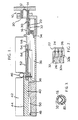
- Figure 1 is a section through a sample feed system for a mass spectrometer, and
- Figure 2 is a partial plan view of the sample magazine used in the feed system of Figure 1, and
- Figure 3 is a section through a sample tube containing boat, the section being taken through a plane passing through the surrounding O-ring.
- In Figure 1, there is shown at 10 part of the inlet system of the mass spectrometer. The
inlet system 10 is not shown in detail but is preferably as described in GB-A-2,141,230. For the purposes of the present application, it suffices to know that theinlet system 10 has anaperture 12 with aconical mouth 14 against which atube 16 containing a sample to be analysed is sealed, the sample resting on a metal boat within thetube 16. - After the
tube 16 has been sealed against theaperture 12, the inlet system of the mass spectrometer evacuates the interior of thetube 16 and pyrolyses the sample by means of aninduction coil 20 surrounding thetube 16. Thecoil 20 heats the boat in thetube 16 to a predetermined temperature (its Curie temperature) and thus pyrolyses the sample, the pyrolysate entering the vacuum chamber for analysis. After completion of the analysis, thetube 16 is withdrawn and replaced by a new tube. - The
tubes 16, which are to contain the analysis samples, are arranged in amagazine 22 which is advanced automatically by the feed system. As seen in the plan view of Figure 2, themagazine 22 hasparallel recesses 24 on its top face for receiving thetubes 16. Each recess is in the form of a semi-cylindrical trough which is enlarged at one end (left end as viewed). Because of thisenlargement 26, the end of eachsample tube 16 is surrounded by a gap while resting in therecess 24 thereby enabling a pick-up tube to be slipped over the end of thesample tube 16 so that it may be picked up from themagazine 22. Each recess also has a further enlargeddiameter portion 28 which serves to accommodate an 0-ring 30 surrounding each of thesample tubes 16. - It is envisaged that the
magazine 22 complete with thesample tubes 16 each fitted with an 0- ring and a metal boat may be sold in sealed packages ready for the samples to be placed on the metal boats by the operator. To assist in loading the boats with samples, the ends of the sample tubes are inset from the edge of themagazine 22 and the boats project from thesample tubes 16 but not beyond the edge of themagazine 22. - Because the samples are pyrolysed by the heating of the boats rather than the
tubes 16, it is preferred to ensure that the samples are not cooled by contact with tubes. To achieve this, eachboat 80 is V-shaped in cross section, as shown in Figure 3, and makes contact with thetube 16 at the upper edges of its limbs but not at its base where the sample rests, the boat being wedged within thetube 16 by its own resilience. Such construction of the boats is also advantageous in that it reduces manufactuing costs. - The lower side of the
magazine 22 is formed with a groove 32 (shown in dotted lines in Figure 2) which is engaged by a spring biassed indexingpin 34 and acts as part of an indexing mechanism for advancing the magazine automatically, as described in more detail below. - The
groove 32 is in the form of a cpntinuous zig- zag formed ofportions 32a which are parallel to and aligned with therecesses 24 and relativelyinclined portions 32b connecting one end of eachportion 32a with the opposite end of theadjacent portion 32a. Viewed in the vertical section of Figure 1, theportions 32a of thegroove 32 slope downwards from left to right whereas theportions 32b slope upwards from left to right. - The indexing
pin 34 is mounted on anindexing bar 36 which reciprocates from left to right in Figure 1. As thepin 34 moves to the right, as viewed, it slides along one of theportions 32a without moving themagazine 22 but is itself deflected downwards. Oh reaching the end of its travel, thepin 34 engages the end of thecontiguous portion 32b and is clicked upwards into theportion 32b by its spring. When now theindexing bar 36 is retracted, the pin slides along theportion 32b and simultaneously moves the magazine to align thenext sample tube 16 with the feed system and theaperture 12. Once again, on reaching the end of its travel the pin clicks into the nextcontiguous portion 32a of the tube. - An advantage of the above construction of the indexing system is that the movement of the
pin 34 is aligned with the inlet aperture and theportion 32a of the groove are all aligned withrecesses 24. As a result, when themagazine 22 is first placed with the indexingpin 34 engaged in any one of theportions 32a, one of the sample tubes will always be correctly aligned for introduction into the inlet system of the mass spectrometer. The magazine need not therefore always be fed in at its start and one may commence analysis at any desired tube on the magazine, Futhermore, the magazine merely rests by its own weight on the indexingpin 34 so that there is no obstruction to raising and lowering themagazine 22 in any of its positions. - It will also be noticed that the movement of the magazine occurs on the return stroke of the indexing pin rather than its forward stroke. The
pin 34, as will be described below, is moved with the mechanism feeding thetubes 16 into theinlet system 10, and as a result the tube aligned with theinlet aperture 12 when the magazine is brought to rest on theindex pin 34 will be the tube first fed into the inlet system for analysis. - The
indexing bar 36 is provided on its upper surface with an elongated slot in which engages apin 38 mounted on acarriage 40, the slot andpin 38 together constituting a lost motion coupling. The total stroke of theindexing bar 36 is therefore shorter than the stroke of thecarriage 40 by the length of the slot in the upper surface of the indexing bar and the latter only follows the movement of the carriage at the end of the forward and return strokes. - The
carriage 40 is guided between two verticallateral guide plates 42 of which only one is seen in Figure 1. The upper surface of the carriage is in the form of arack 44 engaged by a motor drivenpinion 46. Thecarriage 40 rides onrollers 48 which follow acam track 50. As the carriage is moved from left to right, as viewed, the effect of the cam track is to raise and lower thecarriage 40 while enabling it to maintain a horizontal attitude. The motor driving thepinion 46 is also mounted to move vertically with movement of thecarriage 40 and is conveniently mounted on an arm pivotably supported on the outer surface of one of theguide plates 42. - The
carriage 40 has projecting from its front end a pick-up tube 52 which is split longitudinally at its forward end (the right end as viewed). An ejector pin 54 is received within the pick-up tube 52 at its forward end, the pin 54 havingarms 56 which project laterally through the slits in the pick-uptube 52 and move in slots 58 formed in the twoguide plates 42. A ring of an elastic material encircles the forward end of the pick-up tube 52 so that the halves of the tubes are urged resiliently towards each other. - The feed system is shown in Figure 1 at the commencement of a feed cycle. The
magazine 22 is positioned as earlier described such that one of thesample tubes 16 is aligned with theaperture 12. The motor driving thepinion 46 is now energised and moves thecarriage 40 to the right, as viewed, The pick-uptube 52 is moved until its end engages the rear of the sample tube and grips it by virtue of the resilience of the surrounding band. - After this has occurred, the
rollers 48 ride on the cam track ramps and raise the carriage while thesample tube 16 is maintained horizontal. Thearms 56 of the ejector pin at this time are aligned with the ends of the slots 58 and move up the vertical section of the slots. As the pick-up tube 52 continues its forward motion the ejector pin 54 is retracted down the pick-up tube 52. - The ramps on the
cam track 50 are dimensioned to raise the sample tube to the level of theaperture 12 of the inlet system of the mass spectrometer. Thecarriage 40 continues to move forward until first the end of thesample tube 16 abuts theconical surface 14. As thecarriage 40 moves still further the pick-uptube 52 engages the 0-ring 30 and slides it over the outer surface of thesample tube 16. Finally, when the 0-ring 30 abuts theconical surface 14 it is compressed by the pick-uptube 52 and forms a seal. The motor remains energised even after a seal is made to keep a constant pressure on the 0-ring 30. - The mass spectrometer now evacuates the
sample tube 16 and performs its analysis. After the analysis is complete, the motor driving thepinion 46 is reversed and thecarriage 40 moves back towards its illustrated retracted positions. The vacuum seal is first broken by the inlet system so that thesample tube 16 may move freely with the pick-uptube 52. As the pick-up tube is withdrawn, the ejector pin 54 is prevented from moving with it by abutment of its arms with the slots 58. The pin 54 thus forms a stop limiting the movement of thesample tube 16 and after it has been pulled clear of thecoil 20 it drops back into itsown recess 24 in themagazine 22. It is noted that themagazine 22 has still not been moved until this point in the cycle. - The
carriage 40 now rides down the ramps of thecam track 50 so that the arms of the ejector pin 54 are freed by the slots 58 and ejector pin moves back with thetube 52. Thepin 38 at this stage abuts the rear end of the slot in the upper surface of theindexing bar 36 so that the latter is moved to the left and, as earlier described, advances the magazine so that the next sample tube is aligned with theaperture 12. - The control of the feed system and the evacuation system is performed by a micro-computer which may also serve to correlate the spectrum of the sample, as evaluated by the spectrometer, with a library of stored spectra as as to analyse the spectrum automatically. The entire analysis of a batch of samples may thus be performed rapidly and automatically.
- The magazine offers the advantage that the indexing movement is performed automatically without undue complication of the feed system. The magazine may be furthermore inserted and withdrawn in any position and alignment of the sample tubes is always assured.
- Though the magazine has been described as a flat rectangular block, it will be clear that it may alternatively be formed as a large diameter carousel unit rotating about a vertical axis.
Claims (6)
Priority Applications (1)
| Application Number | Priority Date | Filing Date | Title |
|---|---|---|---|
| AT84904152T ATE34880T1 (en) | 1983-11-22 | 1984-11-20 | SAMPLE INLET INTO A MASS SPECTROMETER. |
Applications Claiming Priority (2)
| Application Number | Priority Date | Filing Date | Title |
|---|---|---|---|
| GB08331094A GB2150290A (en) | 1983-11-22 | 1983-11-22 | Introduction of samples into a mass spectrometer |
| GB8331094 | 1983-11-22 |
Publications (2)
| Publication Number | Publication Date |
|---|---|
| EP0162073A1 EP0162073A1 (en) | 1985-11-27 |
| EP0162073B1 true EP0162073B1 (en) | 1988-06-01 |
Family
ID=10552140
Family Applications (1)
| Application Number | Title | Priority Date | Filing Date |
|---|---|---|---|
| EP84904152A Expired EP0162073B1 (en) | 1983-11-22 | 1984-11-20 | Introduction of samples into a mass spectrometer |
Country Status (7)
| Country | Link |
|---|---|
| US (1) | US4634865A (en) |
| EP (1) | EP0162073B1 (en) |
| JP (1) | JPS61500463A (en) |
| AU (1) | AU577556B2 (en) |
| DE (1) | DE3471821D1 (en) |
| GB (1) | GB2150290A (en) |
| WO (1) | WO1985002491A1 (en) |
Families Citing this family (8)
| Publication number | Priority date | Publication date | Assignee | Title |
|---|---|---|---|---|
| DE3800189A1 (en) * | 1988-01-07 | 1989-07-20 | Leybold Ag | DEVICE FOR SUPPLYING AND DELIVERING THE SAMPLE IN AN ANALYZING OVEN |
| US5232775A (en) * | 1990-10-23 | 1993-08-03 | Minnesota Mining And Manufacturing Company | Semi-conducting static-dissipative polymeric composites |
| US5409968A (en) * | 1992-11-06 | 1995-04-25 | Minnesota Mining And Manufacturing Company | Controlled conductivity antistatic articles |
| US5609969A (en) * | 1995-06-30 | 1997-03-11 | Minnesota Mining And Manufacturing Company | Static dissipative electronic packaging article |
| US6465776B1 (en) | 2000-06-02 | 2002-10-15 | Board Of Regents, The University Of Texas System | Mass spectrometer apparatus for analyzing multiple fluid samples concurrently |
| US7041374B1 (en) | 2001-03-30 | 2006-05-09 | Nelson Gordon L | Polymer materials with electrostatic dissipative properties |
| JP2005518530A (en) * | 2002-02-26 | 2005-06-23 | サイファージェン バイオシステムズ, インコーポレイテッド | Device and method for automating the transfer of multiple samples to an analytical instrument |
| US8246862B2 (en) * | 2009-07-30 | 2012-08-21 | Eastman Kodak Company | Static dissipative polymeric composition having controlled conductivity |
Family Cites Families (2)
| Publication number | Priority date | Publication date | Assignee | Title |
|---|---|---|---|---|
| DE2548891C3 (en) * | 1975-10-31 | 1983-04-28 | Finnigan MAT GmbH, 2800 Bremen | Sample changer for mass spectrometers |
| DE3002575C2 (en) * | 1980-01-25 | 1983-12-29 | Finnigan MAT GmbH, 2800 Bremen | Device for automatically controllable sample transport into a room of an analyzer that is under high vacuum |
-
1983
- 1983-11-22 GB GB08331094A patent/GB2150290A/en not_active Withdrawn
-
1984
- 1984-11-20 WO PCT/GB1984/000399 patent/WO1985002491A1/en not_active Ceased
- 1984-11-20 JP JP59504311A patent/JPS61500463A/en active Pending
- 1984-11-20 DE DE8484904152T patent/DE3471821D1/en not_active Expired
- 1984-11-20 US US06/760,736 patent/US4634865A/en not_active Expired - Fee Related
- 1984-11-20 AU AU36704/84A patent/AU577556B2/en not_active Withdrawn - After Issue
- 1984-11-20 EP EP84904152A patent/EP0162073B1/en not_active Expired
Also Published As
| Publication number | Publication date |
|---|---|
| DE3471821D1 (en) | 1988-07-07 |
| GB2150290A (en) | 1985-06-26 |
| US4634865A (en) | 1987-01-06 |
| JPS61500463A (en) | 1986-03-13 |
| EP0162073A1 (en) | 1985-11-27 |
| GB8331094D0 (en) | 1983-12-29 |
| AU3670484A (en) | 1985-06-13 |
| WO1985002491A1 (en) | 1985-06-06 |
| AU577556B2 (en) | 1988-09-29 |
Similar Documents
| Publication | Publication Date | Title |
|---|---|---|
| US4076982A (en) | Automatic sample-changer for mass spectrometers | |
| AU577556B2 (en) | Introduction of samples into a mass spectrometer | |
| EP0162072B1 (en) | Introduction of samples into a mass spectrometer | |
| EP0162881B1 (en) | Introduction of samples into a mass spectrometer | |
| CA1170435A (en) | Method and apparatus for manufacturing a wiring harness | |
| EP0418789B1 (en) | Wire processing apparatus and method | |
| JPH0320707B2 (en) | ||
| US4405860A (en) | Automatically controllable loading apparatus for mass spectrometers or the like | |
| CN115139104B (en) | Press pump integrated automatic assembling machine adopting multiple mechanical arms to work cooperatively | |
| US4395818A (en) | Block loader | |
| US4649636A (en) | Wire deploying apparatus and method of using | |
| US3510933A (en) | Apparatus and method for continuously forming intracutaneous injectors | |
| EP0019396B1 (en) | Apparatus for, and a method of, inserting tape mounted terminals into apertures in a workpiece | |
| US3754434A (en) | Chemical analysis | |
| US4652200A (en) | Handling apparatus and method | |
| JPS60120600A (en) | Inserting device | |
| DE2410529A1 (en) | SAMPLE INJECTION SYSTEM | |
| EP0280457B1 (en) | Apparatus for feeding rigid spacers into travellers for a venetian blind | |
| US3334403A (en) | Apparatus for making electrical detonators | |
| CN111715477A (en) | Workpiece conversion device of dispensing conveying platform | |
| CA1126770A (en) | Electrical lead transfer apparatus | |
| GB2178534A (en) | Device and process for the direct introduction of samples into a mass spectrometer | |
| SU983771A1 (en) | Device for stuffing magnetic cores | |
| SU641565A1 (en) | Semi-automatic apparatus for assembling electric machine carbon brushes | |
| SU780351A1 (en) | Resistance spot-welding machine |
Legal Events
| Date | Code | Title | Description |
|---|---|---|---|
| PUAI | Public reference made under article 153(3) epc to a published international application that has entered the european phase |
Free format text: ORIGINAL CODE: 0009012 |
|
| 17P | Request for examination filed |
Effective date: 19850730 |
|
| AK | Designated contracting states |
Designated state(s): AT BE CH DE FR GB LI LU NL SE |
|
| 17Q | First examination report despatched |
Effective date: 19870602 |
|
| GRAA | (expected) grant |
Free format text: ORIGINAL CODE: 0009210 |
|
| AK | Designated contracting states |
Kind code of ref document: B1 Designated state(s): AT BE CH DE FR GB LI LU NL SE |
|
| REF | Corresponds to: |
Ref document number: 34880 Country of ref document: AT Date of ref document: 19880615 Kind code of ref document: T |
|
| REF | Corresponds to: |
Ref document number: 3471821 Country of ref document: DE Date of ref document: 19880707 |
|
| ET | Fr: translation filed | ||
| PG25 | Lapsed in a contracting state [announced via postgrant information from national office to epo] |
Ref country code: AT Effective date: 19881120 |
|
| PG25 | Lapsed in a contracting state [announced via postgrant information from national office to epo] |
Ref country code: SE Effective date: 19881121 |
|
| PG25 | Lapsed in a contracting state [announced via postgrant information from national office to epo] |
Ref country code: LU Free format text: LAPSE BECAUSE OF NON-PAYMENT OF DUE FEES Effective date: 19881130 Ref country code: LI Effective date: 19881130 Ref country code: CH Effective date: 19881130 Ref country code: BE Effective date: 19881130 |
|
| PLBE | No opposition filed within time limit |
Free format text: ORIGINAL CODE: 0009261 |
|
| STAA | Information on the status of an ep patent application or granted ep patent |
Free format text: STATUS: NO OPPOSITION FILED WITHIN TIME LIMIT |
|
| 26N | No opposition filed | ||
| BERE | Be: lapsed |
Owner name: PRUTEC LTD Effective date: 19881130 |
|
| PG25 | Lapsed in a contracting state [announced via postgrant information from national office to epo] |
Ref country code: NL Effective date: 19890601 |
|
| NLV4 | Nl: lapsed or anulled due to non-payment of the annual fee | ||
| PG25 | Lapsed in a contracting state [announced via postgrant information from national office to epo] |
Ref country code: FR Free format text: LAPSE BECAUSE OF NON-PAYMENT OF DUE FEES Effective date: 19890731 |
|
| REG | Reference to a national code |
Ref country code: CH Ref legal event code: PL |
|
| PG25 | Lapsed in a contracting state [announced via postgrant information from national office to epo] |
Ref country code: DE Effective date: 19890801 |
|
| REG | Reference to a national code |
Ref country code: FR Ref legal event code: ST |
|
| PGFP | Annual fee paid to national office [announced via postgrant information from national office to epo] |
Ref country code: GB Payment date: 19891130 Year of fee payment: 6 |
|
| PG25 | Lapsed in a contracting state [announced via postgrant information from national office to epo] |
Ref country code: GB Effective date: 19901120 |
|
| GBPC | Gb: european patent ceased through non-payment of renewal fee | ||
| EUG | Se: european patent has lapsed |
Ref document number: 84904152.0 Effective date: 19890728 |