EP0161878A2 - Dachaufbau - Google Patents
Dachaufbau Download PDFInfo
- Publication number
- EP0161878A2 EP0161878A2 EP85303148A EP85303148A EP0161878A2 EP 0161878 A2 EP0161878 A2 EP 0161878A2 EP 85303148 A EP85303148 A EP 85303148A EP 85303148 A EP85303148 A EP 85303148A EP 0161878 A2 EP0161878 A2 EP 0161878A2
- Authority
- EP
- European Patent Office
- Prior art keywords
- tension
- members
- chords
- diagonal
- roof structure
- Prior art date
- Legal status (The legal status is an assumption and is not a legal conclusion. Google has not performed a legal analysis and makes no representation as to the accuracy of the status listed.)
- Granted
Links
Images


Classifications
-
- E—FIXED CONSTRUCTIONS
- E04—BUILDING
- E04B—GENERAL BUILDING CONSTRUCTIONS; WALLS, e.g. PARTITIONS; ROOFS; FLOORS; CEILINGS; INSULATION OR OTHER PROTECTION OF BUILDINGS
- E04B1/00—Constructions in general; Structures which are not restricted either to walls, e.g. partitions, or floors or ceilings or roofs
- E04B1/342—Structures covering a large free area, whether open-sided or not, e.g. hangars, halls
-
- E—FIXED CONSTRUCTIONS
- E04—BUILDING
- E04B—GENERAL BUILDING CONSTRUCTIONS; WALLS, e.g. PARTITIONS; ROOFS; FLOORS; CEILINGS; INSULATION OR OTHER PROTECTION OF BUILDINGS
- E04B7/00—Roofs; Roof construction with regard to insulation
- E04B7/14—Suspended roofs
Definitions
- the present invention relates to a roof structure constructed of tension members and compression members and suitable for spanning delineated areas of various size for providing a protective roof thereover for stadiums, arenas, and the like.
- dome and roof structures have been constructed of light weight membranes in order to achieve lower cost and to improve their performance. These structures have been constructed of either synclastic surfaces held-up and stiffened by air pressure or anticlastic surfaces formed by ridged arches, masts, and/or cables against which the membrane has been pre-stressed.
- the synclastic surface may have a low aspect ratio, that is, the ratio of surface area to delineated plan area.
- the resulting low aspect ratio has an important advantage for permanent membrane roofs, such as low profile air structures, since the membrane cost is as much as 70% of the roof cost, the balance being cables, clamps, and compression ring.
- the disadvantage of the air structure has been its dependence on mechanical systems for keeping the roof up and the resulting requirement for providing air tight buildings, snow melting systems, emergency generators, revolving doors, and the like.
- the anticlastic surface has a very high aspect ratio resulting in higher roof costs per unit of delineated plan area.
- those anticlastic surfaces employing masts and cables have high aspect ratios in order to provide sufficiently low membrane stress, while those utilizing arches have high aspect ratios due to design considerations such as arch buckling.
- a tension structural system such as a cable truss dome, which is suitable for spanning large areas where the tension elements support a light weight membrane, which provides a low aspect ratio eliminating the need for supporting air pressure, and which can be erected easily.
- the invention provides a roof structure for spanning a delineated area, said structure comprising support members spanning said delineated area for supporting a roof thereon, characterised in that said support members comprise tension members and compression members said tension members forming top chords spanning a portion of said delineated area and diagonal chords extending therefrom, said compression members attached between said top chords and said diagonal chords, and lower tension members connected to the bottom of said compression members.
- the invention provides a method of erecting a roof structure comprising tension members and compression members for spanning a delineated area, said method comprising the steps of spanning said delineated area with said tension members, attaching one end of said compression members to said tension members at predetermined locations, attaching the other end of said compression members to said tension members to form diagonal chords therefrom, and tensioning said tension members spanning said delineated area to form said roof structure.
- the roof structure preferably comprises a flexible membrane as the roof, held down on the support members by means of tensioning means such as valley cables extending between adjacent support members. This has the advantage of resisting wind-induced uplift forces which sometimes exceed the deadweight of the roof structure.
- Fig. 1 is a plan view of a roof structure 100 in the form of a cable truss dome.
- the cable truss dome 100 forms an undulating supporting surface and is constructed of a plurality of arched support members 102 arranged radially to a delineated area thereby to form a dome covering a space such as a stadium or arena.
- the support members 102 are constructed of a plurality of stranded cables 104 constituting a single, compound tension member and a plurality of rigid struts 106 forming compression members.
- the cables 104 are attached to a continuous compression ring 108 which is arranged to circumscribe the delineated area to be covered.
- the compression ring 108 acts as a foundation to the roof structure, and consists of several chords joined end-to-end.
- the cables 104 may be secured to a plurality of individual anchorage blocks (not shown) buried in the ground at locations spaced around the perimeter of the delineated area.
- the compression ring 108 can be constructed as a portion of the perimeter wall defining the stadium or arena to be covered.
- the cables 104 extend radially from the compression ring 108 overlying a portion of the delineated area.
- Some cables 104 have their other inner ends secured to a central tension ring 110; others have their inner ends secured to the top or bottom of struts 106, as shown in greater detail in Figs. 3 and 4.
- Cables 104 extending from the compression ring 108 to the central tension ring 110 form upper tension chords 112 or ridge cables of the support members 102.
- a number of these cables 104 initiating from the compression ring 108 diverge from the upper chords and constitute diagonal tension chords 114 extending downwardly at an angle from successive predetermined locations along the support members 102.
- a plurality of cables 104 are secured to the compression ring 108 and extend radially towards the tension ring 110.
- a number (one or more) of cables 104 are peeled away from the remaining cables and are arranged extending downwardly from those remaining cables forming the upper tension chord 112, to provide a first diagonal tension chord 114.
- a number of cables 104 are again peeled away from the remaining cables 104 and extend at an angle downwardly from those remaining cables forming the next upper chord 112 to provide the next diagonal chord 114.
- the upper chords 112 and underlying diagonal chords 114 form two adjacent sides of a triangle.
- Struts 106 are connected between the upper chords 112 and diagonal chords 114 to complete the third side of each triangle by means of the structure shown in Figs.
- Each support member 102 comprises a discrete series of such triangles each connected to one or two neighbouring triangles only at respective vertices, so that the triangles do not share common sides.
- the strut 106 of one triangle has its upper end attached to the cables 104 at the intersection of the upper chord 112 and diagonal chord 114 of an adjacent triangle nearer the centre of the structure.
- the number of cables 104 forming successive upper chords 112 successively decreases towards the centre of the structure, as a corresponding number of these cables are peeled away to provide the diagonal chords 114.
- the number of cables 104 contained within each diagonal chord 114 is preferably the same, although it may vary.
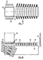
- a plurality of concentric tension rings 116 each constructed of stranded cables 118 are secured to the lower ends of corresponding struts 106 of adjacent support members 102 as best shown in Figs. 7 and 8.
- a flexible membrane 120 serving as a roof over the delineated area.
- the membrane 120 may be formed of a woven synthetic fabric, although it is contemplated that other materials such as canvas or thin metallic formed membranes may also be utilized.
- the membrane 120 is constructed to be weather resistant and preferably of a non-combustible composition. Coated fabrics may be employed for the membrane 120 such as Teflon (Registered Trade Mark) coated glass fibre, silicon-coated glass fibre, silicon-coated polyester, and the like.
- the membrane 120 can be translucent to allow light into the enclosed volume, and may be adapted to provide good acoustic properties.
- a plurality of valley cables 122 are positioned between adjacent support members 102 and extend between the compression ring 108 and tension ring 110.
- the flexible membrane 120 is maintained under tension by prestressing the valley cables 122, for example, as disclosed in U.S. Patent No. 3,807,421. That portion of the flexible membrane 120 extending in V-shaped cross-section between adjacent support members 102 can be in the form of rectangles, trapezoids, triangles, wedge shapes, and the like.
- the flexible membrane 120 can be constructed of a plurality of triangular shaped panels radiating outwardly from the central tension ring 110 such that the joints between adjacent panels can be continuously heat-sealed or adhered in place during field installation so that there are no joints intersecting with those of adjacent panels.
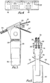
- each strut 106 is attached to the cables 104 at a predetermined location by means of a hanger 124.
- the upper end of the hanger 124 is provided with a pivotable U-shaped bracket 126 through which the cables 104 extend.
- a number of cables may be terminated and secured to the hanger by means of a fixture 128.
- a number of cables 104 extend through the U-shaped bracket 126 and are displaced at an angle downwards to provide the diagonal chords 114.
- supplemental diagonal chords 114 1 may be employed by securing same between the hanger 124 and the lower end of an adjacent strut 106 as shown.
- Bracing between adjacent support members 102 is not required due to the fact that the cables 104 forming the upper chords 112 and diagonal chords 114 are under tension.
- trussing or cross-bracing between adjacent support members I02 can be provided for the purpose of load redistribution and facilitating the erection of the cable truss dome 100.
- the trussing or bracing can be achieved by providing cross-bracing in the form of diagonal cables 130 secured between corresponding struts 106 of adjacent support members 102.
- the diagonal cables 130 are secured at one end to the hangers 124 and attached at their other ends to the lower ends of corresponding struts 106, as shown in Figs. 7 and 8.
- the diagonal cables 130 are shown seven in number, it is expected that only two or three such diagonal cables would be required. To facilitate load redistribution, these diagonal cables are clamped at their crossing point.
- the cables 104 continuing through the hangers 124 within a support member 102 are secured to the central tension ring 110 in the manner shown in Figs. 3 and 4.
- the valley cables 122 are also secured to the central tension ring 110 between adjacent cables 104.
- the support members 102 have one end attached to the tension ring 110 and extend radially outward therefrom, while having their other ends attached to the compression ring 108.
- the lower ends of the struts 106 are provided with a support 132 arranged generally transverse to the strut and extending outwardly along the direction of the support members 102.
- the support 132 is adapted for securing the cables 118 of the individual concentric tension rings 116 thereto.
- a platform 134 is disposed overlying the cables 118 to provide a catwalk for maintenance and installation personnel.
- the platform 134 overlies the concentric tension rings 116 between adjacent struts 106, and a safety handrail 136 is provided on either side of the platform.
- the cable truss dome 100 incorporates a structural system that uses trusses that have upper chords 112 made of tension members comprising a plurality of prestressed cables 104.
- the cables 104 are anchored to the compression ring 108 or buried anchorage blocks (not shown).
- the diagonal chords 114 are discontinuous from one another, are attached to the nested, concentric tension rings 116.
- the rise of the dome can be made as shallow as possible consistent with water drainage and the functions required of the enclosed space.
- the aspect ratio i.e. the ratio of dome surface area to delineated plan area, can be made a minimum.
- the anticlastic membrane surface can be prestressed by the valley cables 122 that pull the flexible membrane 120 down against the upper chords 112 of each of the support members 102.
- these elements can be combined with rigid elements such as beams or trusses in such a manner so as to impart additional stiffness to these elements without introducing compression forces.
- the uniqueness of the cable truss dome 100 is demonstrated by the fact that it is not triangulated.
- the rigidity of a triangular structure is not required of the cables truss dome 100 as structural roof membranes, i.e., architectural fabrics, permit the membrane to act as both a deck and a weathering membrane.
- This membrane if properly shaped and prestressed, can accommodate the large displacements of a structural system that is not triangulated.
- non-linear large displacement structural analysis is possible using digital computers.
- the cable truss dome 100 can be formed with either circular or non-circular plan configurations based on skewed symmetric principles, for example as in U.S. Patent No. 3,841,038.
- the prestressed flexible membrane 120 covering the cable truss dome 100 has shallow undulations permitting the aspect ratio to be a minimum thus allowing maximum economy in the flexible membrane.
- the use of the cable truss dome 100 is a practical consideration because of the efficiency with which the cable end forces can be resisted through the use of skewed symmetric compression rings or anchorage blocks. Given the flexibility of the cable truss dome 100, and the fact that it is not triangulated, such facts are advantages because the cable truss dome can be largely assembled on the ground or in a hanging position, with or without the flexible membrane 120, and then hoisted into position using simple cable tensioning devices that are used to put the final tension into the cables 104, as described below.
- the method for erection of the cable truss dome 100 uses the natural propensity for cables to drape in a concave upward position between anchor points under gravity.
- the tension ring 110 is supported on a scaffolding 138 or alternatively may be positioned on the ground and hoisted in place by jacking of the ridge cables.
- a bundle of cables 104, including the upper chords 112 and diagonal chords 114 for the support members 102, are positioned radially about the delineated area to be covered.
- the perimeter ends of the cables 104 are secured to the compression ring 108 while the other ends of those cables providing the upper chords 112 are secured to the tension ring 110.
- Those cables 104 providing the diagonal chords 114 are allowed to drape downwardly from the remaining cables at successive locations corresponding to the positions for the struts 106 along each support member 102.
- the lengths of some of the diagonal chords 114 are greater than required in the erected cable truss dome 100, in order to facilitate the erection, as described below.
- the struts 106 having attached hangers 124 and supports 132, are positioned on the ground, scaffolding and/or stadium seating as shown in Fig. 6.
- the struts 106 are securely set so that their plan position relative to each other is maintained during the attachment of the concentric tension rings 116.
- the cables 118 are spun overlying the supports 132 of corresponding 106 to provide the plurality of concentric tension rings 116.
- the tension rings 116 are slightly tensioned as they are attached to the supports 132 of each of the struts 106.
- the struts 106 having attached hangers 124, supports 132 and tension rings 116 are lifted vertically upward and secured to those cables 104 forming the upper chords 112.
- the hangers 124 may be attached to the cables 104 first and the struts 106 can be attached later to the hangers during final erection of the cable truss dome 100.
- the attachment of the hangers 124, to the cables 104 is achieved by pivotally attaching the U-shaped bracket 126 over the cables 104 to the upper end of the hangers 124, and securing the cables thereto by means of the fixture 128.
- the cables 104 providing the diagonal chords 114 are inserted through the lower end of the struts 106. This procedure is repeated for all concentric rings formed by corresponding struts 106 and the tension rings 116.
- cables 104 may then be arranged spanning the delineated area by successively attaching them to the top of one strut and then to the bottom of an adjacent strut, so as to form the diagonal chords 114 therebetween.
- This alternative method allows the cable truss dome 100 to be easily assembled and erected from a ground level position.
- the interior tension rings 116 are spun at grade level or on a support structure such as stadium seating and lifted with the struts 106 for attaching same to the cables 104 providing the upper chords 112.
- the cables 104 forming the upper chords 112 are in an inverted position and are subsequently made to assume a concave downward position by simultaneous shortening of the diagonal chords 114, one concentric ring at a time, so as to cause the support members 102 to reverse their curvature one ring at a time.
- the flexible membrane 120 may be attached to the cables 104 and valley cables 122 for inflating the roof structure using mechanical blowers.
- the upward movement of the flexible membrane 120 by means of mechanical blowers causes the reversing of the curvature of the support members 102 and brings the struts 106 approximately into their final positions, at which the diagonal chords 114 are then attached.
- the struts 106 are then brought into their final position in which the support members 102 assume a concave downward position, at which time the internal pressure created by the mechanical blowers is no longer required to hold the cable truss dome 100 up.
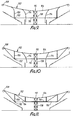
- the cable truss 140 is constructed of a plurality of tension members 142 arranged to span the delineated area, to be covered with, for example, a flexible member 120 of the type illustrated in Fig. 1.
- the tension members 142 are constructed of stranded cables of the type described and illustrated with respect to the previous embodiment, and are anchored in the same way to buried blocks or to a compression ring 108.
- the tension members 142 each overlie a portion of the delineated area and have their other ends secured to a central tension ring 144 in the manner to be described, or, in the case of a linear truss, secured to the other side.
- the cable truss 140 also includes a plurality of rigid struts 146, which may be of varying length, and which form compression members similar in function to the struts 106 as shown in Fig. 2.
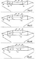
- the tension members 142 are arranged in the cable truss 140 to form upper chords 148, diagonal chords 150 and lower chords 152. As shown, the number of cables within the upper chords 148 decreases from the compression ring I08 to the tension ring 144, while the number of cables within the lower chords 152 increases from the compression ring to the tension ring.
- a plurality of continuous tension members 142 are secured to the top of a first strut 146, thereby forming an upper chord 148 between the compression ring 108 and first strut 146.
- a tension member 142 is attached to the bottom end of an adjacent second strut 146' to form a diagonal chord 150 therebetween.
- the tension member 142 forming the diagonal chord 150 is then attached to the bottom end of the remaining strut 146" and has its free end attached to the lower end of the tension ring 144.
- the remainder of the tension members 142 attached to the top end of the first strut 146, are secured to the top end of the adjacent second strut 146' to form an upper chord 148.
- the number of cables in the upper chord 148 running between the adjacent first and second struts 146, 146' is less than the number of cables in the upper chord running between the compression ring 108 and first strut 146.
- a tension member 142 connected to the top of the second strut 146' is attached to the lower end of the adjacent third strut 146" to form diagonal chord 150, and ultimately to the lower end of the tension ring 144 to form a lower chord 152.
- the remaining tension members 142 attached to the upper end of the second strut 146' are attached to the upper end of the adjacent third strut 146" in the previous manner described.
- the tension members 142 extend continuously from the compression ring 108 to the tension ring 144 in the form of an upper chord 148, a diagonal chord 150 and a lower chord 152.
- the struts 146, 146', 146" are secured between the upper chords 148 and lower chords 152 to maintain the tension members 142 under tension upon application of a load.
- the struts 146 are secured to the tension members 142 by means of saddle-type brackets 154, 154 t .
- the upper and lower brackets 154, 154' are secured to the ends of the strut 146.
- the upper bracket 154 is provided with a pair of spaced ears 156 between which the tension members 142 are retained.
- the lower bracket 154' is in turn provided with a U-shaped retainer plate 158 to sandwich the tension members 142 therebetween, which tension members are also confined between spaced bushes 160. In this manner, the struts 146 are attached between the tension members 142, so as to maintain the tension members under tension during an applied load.
- a bundle of tension members 142 is arranged overlying the delineated area between the compression ring 108 and tension ring 144.
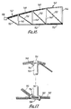
- a plurality of struts a46 are attached to the tension members 142 at intermediate locations between the compression ring 108 and tension ring 144, so that the tension members are divided into upper chords 148, diagonal chords 150 and lower chords 152, as shown in Fig. 16.
- the tension members 142 and struts 146 may be assembled on the ground or using a scaffolding 138 in the manner previously described.
- the cable truss 100 is erected by tensioning the tension members 142 by engaging their free ends at their location at the compression ring 108.
- the tension members 142 are respectively tensioned by shortening their length between the compression ring 108 and tension ring 144, so that the tension members forming the upper chords 148, diagonal chords 150 and lower chords 152 are placed under tension, which then lifts the outer portion of the cable truss 140 upwardly.
- tension members 142 which form the next adjacent inward diagonal chord 150, all tension members within the cable truss 140 are placed under tension, thereby causing the cable truss to be raised into its tensioned self-supporting position, as shown in Fig. 16.
- cross-bracing 130 may be provided between adjacent corresponding struts 146.
- the cable truss 140 can then be covered with a flexible member 120 which may be pre-stressed by the tensioning of valley cables 122 attached between the tension ring 144 and compression ring 108.
Landscapes
- Engineering & Computer Science (AREA)
- Architecture (AREA)
- Electromagnetism (AREA)
- Civil Engineering (AREA)
- Structural Engineering (AREA)
- Physics & Mathematics (AREA)
- Tents Or Canopies (AREA)
- Superconductors And Manufacturing Methods Therefor (AREA)
- Buildings Adapted To Withstand Abnormal External Influences (AREA)
- Paper (AREA)
- Roof Covering Using Slabs Or Stiff Sheets (AREA)
- Vehicle Interior And Exterior Ornaments, Soundproofing, And Insulation (AREA)
- Residential Or Office Buildings (AREA)
- Building Environments (AREA)
Priority Applications (1)
| Application Number | Priority Date | Filing Date | Title |
|---|---|---|---|
| AT85303148T ATE55441T1 (de) | 1984-05-04 | 1985-05-02 | Dachaufbau. |
Applications Claiming Priority (2)
| Application Number | Priority Date | Filing Date | Title |
|---|---|---|---|
| US60842484A | 1984-05-04 | 1984-05-04 | |
| US608424 | 1984-05-04 |
Publications (3)
| Publication Number | Publication Date |
|---|---|
| EP0161878A2 true EP0161878A2 (de) | 1985-11-21 |
| EP0161878A3 EP0161878A3 (en) | 1986-12-17 |
| EP0161878B1 EP0161878B1 (de) | 1990-08-08 |
Family
ID=24436450
Family Applications (1)
| Application Number | Title | Priority Date | Filing Date |
|---|---|---|---|
| EP85303148A Expired - Lifetime EP0161878B1 (de) | 1984-05-04 | 1985-05-02 | Dachaufbau |
Country Status (8)
| Country | Link |
|---|---|
| EP (1) | EP0161878B1 (de) |
| JP (1) | JPS60238556A (de) |
| KR (1) | KR920002118B1 (de) |
| AT (1) | ATE55441T1 (de) |
| AU (1) | AU555924B2 (de) |
| BR (1) | BR8502033A (de) |
| CA (1) | CA1234269A (de) |
| DE (1) | DE3579034D1 (de) |
Cited By (8)
| Publication number | Priority date | Publication date | Assignee | Title |
|---|---|---|---|---|
| WO1999041473A1 (en) * | 1998-02-13 | 1999-08-19 | Tentnology Ltd. | Multiple peak cable tent |
| US6345638B1 (en) | 1999-02-15 | 2002-02-12 | Tentnology Ltd. | Multiple peak cable tent |
| CZ303990B6 (cs) * | 2012-06-07 | 2013-07-31 | Stráský, Hustý a partneri s.r.o. | Visutá lanová strecha |
| CN103967125A (zh) * | 2014-05-22 | 2014-08-06 | 中国建筑西南设计研究院有限公司 | 大开口车辐式索承网格结构 |
| CN107419806A (zh) * | 2017-09-18 | 2017-12-01 | 华南理工大学建筑设计研究院 | 一种大跨x型网格立体张弦结构体系及其施工方法 |
| CN109750779A (zh) * | 2019-01-17 | 2019-05-14 | 上海海事大学 | 一种旋转锥面肋环型索穹顶 |
| CN112520254A (zh) * | 2019-09-18 | 2021-03-19 | 中国石油天然气股份有限公司 | 采用正交索梁结构制造罐顶的储罐结构及其施工方法 |
| CN113047440A (zh) * | 2021-05-06 | 2021-06-29 | 上海大学 | 一种带抗风索的双层辐射式张弦梁结构及其施工方法 |
Families Citing this family (7)
| Publication number | Priority date | Publication date | Assignee | Title |
|---|---|---|---|---|
| JP5722856B2 (ja) * | 2012-09-27 | 2015-05-27 | 株式会社アールシーコア | ドーム状構造物 |
| CN103953115B (zh) * | 2014-05-22 | 2016-06-15 | 中国建筑西南设计研究院有限公司 | 大开口葵花型索承网格结构 |
| CN105464213B (zh) * | 2015-10-30 | 2018-08-17 | 北京城建集团有限责任公司 | 一种大跨度预应力圆顶结构及其制作方法 |
| CN105926850A (zh) * | 2016-07-03 | 2016-09-07 | 山东建筑大学 | 一种环形交叉索桁架结构 |
| CN108532758B (zh) * | 2018-06-12 | 2024-04-09 | 江南大学 | 一种双层网壳大跨度环向耗能结构体系 |
| CN111441477B (zh) * | 2020-04-28 | 2024-10-29 | 北京市建筑设计研究院股份有限公司 | 一种碳纤维索加强的轮辐式索桁架结构 |
| CN114575464B (zh) * | 2022-05-07 | 2022-07-22 | 清华大学 | 建筑屋顶构造及施工方法 |
Family Cites Families (6)
| Publication number | Priority date | Publication date | Assignee | Title |
|---|---|---|---|---|
| FR1056325A (fr) * | 1951-02-21 | 1954-02-25 | Système de suspension pour ponts, halles de grande portée, toits et analogues | |
| DE1256863B (de) * | 1964-10-15 | 1967-12-21 | Krug & Co Heinrich | Spanndach |
| FR1446326A (fr) * | 1965-03-31 | 1966-07-22 | Perfectionnements aux structures prétendues, notamment aux structures tridimensionnelles prétendues | |
| DE2146029B1 (de) * | 1971-09-15 | 1973-05-17 | Dachkonstruktion fuer hallen, stadien od. dgl | |
| US3807421A (en) * | 1972-03-13 | 1974-04-30 | David Geiger Horst Berger P C | Prestressed membrane structure |
| FR2207228B1 (de) * | 1972-11-20 | 1975-01-03 | Hillerin Charles De |
-
1985
- 1985-01-30 JP JP60014595A patent/JPS60238556A/ja active Granted
- 1985-04-10 CA CA000478723A patent/CA1234269A/en not_active Expired
- 1985-04-30 BR BR8502033A patent/BR8502033A/pt unknown
- 1985-05-01 AU AU41863/85A patent/AU555924B2/en not_active Ceased
- 1985-05-02 EP EP85303148A patent/EP0161878B1/de not_active Expired - Lifetime
- 1985-05-02 AT AT85303148T patent/ATE55441T1/de not_active IP Right Cessation
- 1985-05-02 DE DE8585303148T patent/DE3579034D1/de not_active Expired - Lifetime
- 1985-05-03 KR KR1019850003023A patent/KR920002118B1/ko not_active Expired
Cited By (12)
| Publication number | Priority date | Publication date | Assignee | Title |
|---|---|---|---|---|
| WO1999041473A1 (en) * | 1998-02-13 | 1999-08-19 | Tentnology Ltd. | Multiple peak cable tent |
| US6345638B1 (en) | 1999-02-15 | 2002-02-12 | Tentnology Ltd. | Multiple peak cable tent |
| CZ303990B6 (cs) * | 2012-06-07 | 2013-07-31 | Stráský, Hustý a partneri s.r.o. | Visutá lanová strecha |
| CN103967125A (zh) * | 2014-05-22 | 2014-08-06 | 中国建筑西南设计研究院有限公司 | 大开口车辐式索承网格结构 |
| CN103967125B (zh) * | 2014-05-22 | 2016-07-20 | 中国建筑西南设计研究院有限公司 | 大开口车辐式索承网格结构 |
| CN107419806A (zh) * | 2017-09-18 | 2017-12-01 | 华南理工大学建筑设计研究院 | 一种大跨x型网格立体张弦结构体系及其施工方法 |
| CN109750779A (zh) * | 2019-01-17 | 2019-05-14 | 上海海事大学 | 一种旋转锥面肋环型索穹顶 |
| CN109750779B (zh) * | 2019-01-17 | 2023-10-31 | 上海海事大学 | 一种旋转锥面肋环型索穹顶 |
| CN112520254A (zh) * | 2019-09-18 | 2021-03-19 | 中国石油天然气股份有限公司 | 采用正交索梁结构制造罐顶的储罐结构及其施工方法 |
| CN112520254B (zh) * | 2019-09-18 | 2022-06-03 | 中国石油天然气股份有限公司 | 采用正交索梁结构制造罐顶的储罐结构及其施工方法 |
| CN113047440A (zh) * | 2021-05-06 | 2021-06-29 | 上海大学 | 一种带抗风索的双层辐射式张弦梁结构及其施工方法 |
| CN113047440B (zh) * | 2021-05-06 | 2023-08-11 | 盐城市建筑设计研究院有限公司 | 一种带抗风索的双层辐射式张弦梁结构及其施工方法 |
Also Published As
| Publication number | Publication date |
|---|---|
| JPS60238556A (ja) | 1985-11-27 |
| EP0161878A3 (en) | 1986-12-17 |
| EP0161878B1 (de) | 1990-08-08 |
| KR920002118B1 (ko) | 1992-03-12 |
| BR8502033A (pt) | 1985-12-31 |
| KR850008105A (ko) | 1985-12-13 |
| AU555924B2 (en) | 1986-10-16 |
| AU4186385A (en) | 1985-11-07 |
| JPH0520536B2 (de) | 1993-03-19 |
| DE3579034D1 (de) | 1990-09-13 |
| CA1234269A (en) | 1988-03-22 |
| ATE55441T1 (de) | 1990-08-15 |
Similar Documents
| Publication | Publication Date | Title |
|---|---|---|
| US4736553A (en) | Roof structure | |
| EP0161878B1 (de) | Dachaufbau | |
| US5146719A (en) | Space tension chord arch dome reinforced with tension members and method for building same | |
| US4757650A (en) | Cable dome system with main cables oriented along chords | |
| US6282842B1 (en) | Inflatable roof support systems | |
| US4680901A (en) | Precast concrete dome system | |
| US4676045A (en) | Post-tensioned steel structure | |
| EP0555396B1 (de) | Dreiecksdachkonstruktion | |
| US5440840A (en) | Triangulated roof structure | |
| US7726078B2 (en) | Roof arches without bending moments | |
| Berger | Form and function of tensile structures for permanent buildings | |
| US5502928A (en) | Tension braced dome structure | |
| EP1257715B1 (de) | Bogenförmige struktur | |
| US4611442A (en) | Large span dome | |
| Levy | Floating fabric over Georgia dome | |
| US4276733A (en) | Method of constructing and erecting a dome-shaped structure | |
| WO1996025572A2 (en) | Inflatable roof support systems | |
| US4651496A (en) | Method of erecting a cable stay roof over an existing structure | |
| US4711063A (en) | Large span dome | |
| CA1240470A (en) | Roof structure | |
| US6026614A (en) | Cable braced, open air chapel/meeting hall | |
| CA1245877A (en) | Precast concrete dome system | |
| EP0081609B1 (de) | Aufgehängtes Dach | |
| Mollaert | Membrane structures: understanding their forms | |
| Butler | LONG SPAN CABLE ROOF STRUCTURES. |
Legal Events
| Date | Code | Title | Description |
|---|---|---|---|
| PUAI | Public reference made under article 153(3) epc to a published international application that has entered the european phase |
Free format text: ORIGINAL CODE: 0009012 |
|
| AK | Designated contracting states |
Designated state(s): AT BE CH DE FR GB IT LI LU NL SE |
|
| PUAL | Search report despatched |
Free format text: ORIGINAL CODE: 0009013 |
|
| AK | Designated contracting states |
Kind code of ref document: A3 Designated state(s): AT BE CH DE FR GB IT LI LU NL SE |
|
| 17P | Request for examination filed |
Effective date: 19870413 |
|
| 17Q | First examination report despatched |
Effective date: 19880708 |
|
| GRAA | (expected) grant |
Free format text: ORIGINAL CODE: 0009210 |
|
| AK | Designated contracting states |
Kind code of ref document: B1 Designated state(s): AT BE CH DE FR GB IT LI LU NL SE |
|
| PG25 | Lapsed in a contracting state [announced via postgrant information from national office to epo] |
Ref country code: SE Free format text: THE PATENT HAS BEEN ANNULLED BY A DECISION OF A NATIONAL AUTHORITY Effective date: 19900808 Ref country code: NL Effective date: 19900808 Ref country code: LI Effective date: 19900808 Ref country code: IT Free format text: LAPSE BECAUSE OF FAILURE TO SUBMIT A TRANSLATION OF THE DESCRIPTION OR TO PAY THE FEE WITHIN THE PRESCRIBED TIME-LIMIT;WARNING: LAPSES OF ITALIAN PATENTS WITH EFFECTIVE DATE BEFORE 2007 MAY HAVE OCCURRED AT ANY TIME BEFORE 2007. THE CORRECT EFFECTIVE DATE MAY BE DIFFERENT FROM THE ONE RECORDED. Effective date: 19900808 Ref country code: CH Effective date: 19900808 Ref country code: BE Effective date: 19900808 Ref country code: AT Effective date: 19900808 |
|
| REF | Corresponds to: |
Ref document number: 55441 Country of ref document: AT Date of ref document: 19900815 Kind code of ref document: T |
|
| REF | Corresponds to: |
Ref document number: 3579034 Country of ref document: DE Date of ref document: 19900913 |
|
| ET | Fr: translation filed | ||
| REG | Reference to a national code |
Ref country code: CH Ref legal event code: PL |
|
| NLV1 | Nl: lapsed or annulled due to failure to fulfill the requirements of art. 29p and 29m of the patents act | ||
| PG25 | Lapsed in a contracting state [announced via postgrant information from national office to epo] |
Ref country code: LU Free format text: LAPSE BECAUSE OF NON-PAYMENT OF DUE FEES Effective date: 19910531 |
|
| PLBE | No opposition filed within time limit |
Free format text: ORIGINAL CODE: 0009261 |
|
| STAA | Information on the status of an ep patent application or granted ep patent |
Free format text: STATUS: NO OPPOSITION FILED WITHIN TIME LIMIT |
|
| 26N | No opposition filed | ||
| REG | Reference to a national code |
Ref country code: GB Ref legal event code: IF02 |
|
| PGFP | Annual fee paid to national office [announced via postgrant information from national office to epo] |
Ref country code: GB Payment date: 20030430 Year of fee payment: 19 |
|
| PGFP | Annual fee paid to national office [announced via postgrant information from national office to epo] |
Ref country code: FR Payment date: 20030508 Year of fee payment: 19 |
|
| PGFP | Annual fee paid to national office [announced via postgrant information from national office to epo] |
Ref country code: DE Payment date: 20030515 Year of fee payment: 19 |
|
| PG25 | Lapsed in a contracting state [announced via postgrant information from national office to epo] |
Ref country code: GB Free format text: LAPSE BECAUSE OF NON-PAYMENT OF DUE FEES Effective date: 20040502 |
|
| PG25 | Lapsed in a contracting state [announced via postgrant information from national office to epo] |
Ref country code: DE Free format text: LAPSE BECAUSE OF NON-PAYMENT OF DUE FEES Effective date: 20041201 |
|
| GBPC | Gb: european patent ceased through non-payment of renewal fee |
Effective date: 20040502 |
|
| PG25 | Lapsed in a contracting state [announced via postgrant information from national office to epo] |
Ref country code: FR Free format text: LAPSE BECAUSE OF NON-PAYMENT OF DUE FEES Effective date: 20050131 |
|
| REG | Reference to a national code |
Ref country code: FR Ref legal event code: ST |