EP0161746B1 - Vented nestable pouring spout - Google Patents
Vented nestable pouring spout Download PDFInfo
- Publication number
- EP0161746B1 EP0161746B1 EP85301396A EP85301396A EP0161746B1 EP 0161746 B1 EP0161746 B1 EP 0161746B1 EP 85301396 A EP85301396 A EP 85301396A EP 85301396 A EP85301396 A EP 85301396A EP 0161746 B1 EP0161746 B1 EP 0161746B1
- Authority
- EP
- European Patent Office
- Prior art keywords
- spout
- ears
- orientation
- container
- pouring
- Prior art date
- Legal status (The legal status is an assumption and is not a legal conclusion. Google has not performed a legal analysis and makes no representation as to the accuracy of the status listed.)
- Expired
Links
- 210000005069 ears Anatomy 0.000 claims description 30
- 239000007788 liquid Substances 0.000 claims description 18
- 230000002093 peripheral effect Effects 0.000 claims description 14
- 238000010276 construction Methods 0.000 claims 1
- 238000013022 venting Methods 0.000 description 12
- 230000010349 pulsation Effects 0.000 description 4
- 239000012530 fluid Substances 0.000 description 3
- 229920003023 plastic Polymers 0.000 description 3
- 239000004033 plastic Substances 0.000 description 3
- 238000004519 manufacturing process Methods 0.000 description 2
- 239000004698 Polyethylene Substances 0.000 description 1
- 229910000831 Steel Inorganic materials 0.000 description 1
- HCHKCACWOHOZIP-UHFFFAOYSA-N Zinc Chemical compound [Zn] HCHKCACWOHOZIP-UHFFFAOYSA-N 0.000 description 1
- 239000000853 adhesive Substances 0.000 description 1
- 230000001070 adhesive effect Effects 0.000 description 1
- 230000004323 axial length Effects 0.000 description 1
- 229920001903 high density polyethylene Polymers 0.000 description 1
- 239000004700 high-density polyethylene Substances 0.000 description 1
- 239000002184 metal Substances 0.000 description 1
- 229910052751 metal Inorganic materials 0.000 description 1
- 238000000034 method Methods 0.000 description 1
- 238000004806 packaging method and process Methods 0.000 description 1
- -1 polyethylene Polymers 0.000 description 1
- 229920000573 polyethylene Polymers 0.000 description 1
- 238000007493 shaping process Methods 0.000 description 1
- 239000010959 steel Substances 0.000 description 1
- 231100000331 toxic Toxicity 0.000 description 1
- 230000002588 toxic effect Effects 0.000 description 1
- 230000000007 visual effect Effects 0.000 description 1
- 238000003466 welding Methods 0.000 description 1
- 229910052725 zinc Inorganic materials 0.000 description 1
- 239000011701 zinc Substances 0.000 description 1
Images

Classifications
-
- B—PERFORMING OPERATIONS; TRANSPORTING
- B65—CONVEYING; PACKING; STORING; HANDLING THIN OR FILAMENTARY MATERIAL
- B65D—CONTAINERS FOR STORAGE OR TRANSPORT OF ARTICLES OR MATERIALS, e.g. BAGS, BARRELS, BOTTLES, BOXES, CANS, CARTONS, CRATES, DRUMS, JARS, TANKS, HOPPERS, FORWARDING CONTAINERS; ACCESSORIES, CLOSURES, OR FITTINGS THEREFOR; PACKAGING ELEMENTS; PACKAGES
- B65D47/00—Closures with filling and discharging, or with discharging, devices
- B65D47/04—Closures with discharging devices other than pumps
- B65D47/06—Closures with discharging devices other than pumps with pouring spouts or tubes; with discharge nozzles or passages
- B65D47/061—Closures with discharging devices other than pumps with pouring spouts or tubes; with discharge nozzles or passages with telescopic, retractable or reversible spouts, tubes or nozzles
- B65D47/063—Closures with discharging devices other than pumps with pouring spouts or tubes; with discharge nozzles or passages with telescopic, retractable or reversible spouts, tubes or nozzles with flexible parts
-
- B—PERFORMING OPERATIONS; TRANSPORTING
- B65—CONVEYING; PACKING; STORING; HANDLING THIN OR FILAMENTARY MATERIAL
- B65D—CONTAINERS FOR STORAGE OR TRANSPORT OF ARTICLES OR MATERIALS, e.g. BAGS, BARRELS, BOTTLES, BOXES, CANS, CARTONS, CRATES, DRUMS, JARS, TANKS, HOPPERS, FORWARDING CONTAINERS; ACCESSORIES, CLOSURES, OR FITTINGS THEREFOR; PACKAGING ELEMENTS; PACKAGES
- B65D47/00—Closures with filling and discharging, or with discharging, devices
- B65D47/04—Closures with discharging devices other than pumps
- B65D47/06—Closures with discharging devices other than pumps with pouring spouts or tubes; with discharge nozzles or passages
- B65D47/10—Closures with discharging devices other than pumps with pouring spouts or tubes; with discharge nozzles or passages having frangible closures
- B65D47/103—Membranes with a tearing element
-
- B—PERFORMING OPERATIONS; TRANSPORTING
- B65—CONVEYING; PACKING; STORING; HANDLING THIN OR FILAMENTARY MATERIAL
- B65D—CONTAINERS FOR STORAGE OR TRANSPORT OF ARTICLES OR MATERIALS, e.g. BAGS, BARRELS, BOTTLES, BOXES, CANS, CARTONS, CRATES, DRUMS, JARS, TANKS, HOPPERS, FORWARDING CONTAINERS; ACCESSORIES, CLOSURES, OR FITTINGS THEREFOR; PACKAGING ELEMENTS; PACKAGES
- B65D47/00—Closures with filling and discharging, or with discharging, devices
- B65D47/04—Closures with discharging devices other than pumps
- B65D47/06—Closures with discharging devices other than pumps with pouring spouts or tubes; with discharge nozzles or passages
- B65D47/12—Closures with discharging devices other than pumps with pouring spouts or tubes; with discharge nozzles or passages having removable closures
- B65D47/127—Snap-on caps
- B65D47/128—Snap-on caps with internal parts
Definitions
- This invention relates in general to nestable and extendable pouring spouts for containers and in particular to such spouts having a venting means for reducing pulsations in the outflowing liquid.
- Nos. 3,040,938 and 4,295,583 relate particularly to vented spouts.
- a smooth outflow of liquid from the spout of a container is particularly important. Examples are where it is desired to decant a precise amount of liquid from a large stock container into a smaller container or where the liquid is corrosive or toxic and splashing must therefore be avoided.
- Smooth, pulsation-free outflow may be obtained with a conventional spout by carefully controlling the angle of the spout with regard to the fluid level in the container so that the spout never flows full, thereby maintaining an air passageway through the spout into the container.
- One disadvantage of this method is that the required degree of control is often difficult to maintain, especially where the container is heavy.
- Another disadvantage is that only a fraction of the cross sectional area of the spout is available for fluid outflow when the container is near full, thus increasing the time necessary to decant the liquid.
- prior nestable and extendable spouts have been fitted with venting devices for maintaining an air passageway through the spout regardless of the angle of pouring, enabling venting of the container even though the opening of the container is completely submerged (see Smith, 3,040,938 and Schurr, 4,295,583).
- These prior venting devices are essentially tubes mounted concentrically within the neck of the spout so as to form an annular air space between the tube and the neck.
- the base of the tube is fitted with a flange having a plurality of small peripheral channels, which flange is drawn up against the base of the spout when the spout is in its extended orientation. In this orientation, air may enter the container through the annular space and the peripheral channels while the fluid exits through the central tube.
- venting devices Although the venting devices exemplified in Smith ('938) and Schurr ('583) function well, they have non-functional disadvantages associated with their structure. For instance, the venting device must be manufactured as a separate piece which is then mounted within the neck of the spout and secured thereto by welding or adhesive. This is a relatively expensive manufacturing process. Additionally, the venting device adds to the overall axial length of the spout when it is in its nested orientation, thus increasing the handling, packaging and shipping costs of such a spout.
- German patent No. 1924824 Another example of a prior known nestable and extendable pouring spout is shown in German patent No. 1924824.
- This spout includes a deformable "bellows" part by means of which an outer socket end part may take up a nested orientation or an extended pouring orientation with respect to a base flange by means of which the spout is secured to the mouth of a container.
- the spout includes four projections which extend inwardly when the seal is in its extended orientation.
- the spout is intended to reduce splashing of contents when a container is righted, by means of the four projections.
- the projections do not touch or overlap.
- a pouring spout for use with a container comprising a spout having extending means for alternately disposing said spout in a nested orientation or in an extended pouring orientation;
- a plurality of ears attached to the spout, which extend inwardly within the spout when the spout is disposed in the extended pouring orientation (see DE-C-1924824) characterised in that when the spout is disposed in the extended pouring orientation, the plurality of ears cooperates to define a central flow aperture for the outflow of liquid and each pair of adjacent ears defines a peripheral vent opening therebetween for the inflow of air, the cross-section of said central flow aperture being smaller than the interior flow cross-section of any subsequent spout outflow portion.
- One object of the present invention is to provide an improved self-venting nestable pouring spout which is compact and inexpensive to manufacture.
- FIGs. 1 and 2 there is illustrated nestable pouring spout 10 having as its principle components a mounting portion 11, a body portion 12, and a neck portion 13.
- mounting portion 11, body portion 12, and neck portion 13, together with ears 19, seal 24 and pull ring 25 which are described below, are integrally molded from a low density flexible polyethylene plastic.
- Mounting portion 11 is an annular U-shaped channel configured to mount on an annular lip 14 which encompasses a generally circular opening in a container 20.
- Lip 14 may be made of plastic or metal.
- Anchor ring 15, which is preferably constructed of zinc plated steel, is crimped over mounting portion 11 to compress it about and secure it to lip 14, thereby effecting an air-tight, liquid-tight seal between mounting portion 11 and lip 14.
- Body portion 12 is a generally funnel shaped member which is secured at its larger circumferential edge to mounting portion 11 and at its smaller circumferential edge to neck portion 13.
- Body portion 12 includes invertible fold portions 16 and 17, which folds cause body portion 12 to be generally S-shaped in section along a plane parallel to the longitudinal axis 18 of nestable pouring spout 10.
- Body portion 12 is substantially circular in cross-section along a plane perpendicular to axis 18.
- Attached at the outside surface of invertible fold portion 16 is a plurality of circumferentially spaced ears 19, each of which extends downwardly substantially parallel to longitudinal axis 18 when nestable pouring spout 10 is in its nested orientation. In this orientation the ears do not restrict the opening of the container and do not interfere with the attainment of a fully nested orientation by the neck and body portions.
- Ears 19 provide a self-venting action for spout 10, which will be described in greater detail below.
- Neck portion 13 is a generally cylindrical tube having threads 21 near its upper end for threadedly receiving a cap 23 having corresponding threads 22. Disposed within the opening of neck portion 13 is a disk-like seal 24 having a pull ring 25 attached proximate one edge of seal 24. Seal 24 is provided with an annular peripheral groove 26 which provides a weakened point at which seal 24 will break away when pull ring 25 is pulled.
- Cap 23 which is preferably molded from a high density polyethylene plastic, includes integrally molded flexible bail handles 27 which, when cap 23 is threadedly attached to neck portion 13, provide a convenient means for grasping neck portion 13 and pulling it out into its extended orientation, as is shown in Fig. 2.
- tamper indicating seal 28 When nestable pouring spout 10 is in its initial nested orientation prior to opening, there is disposed over cap 23 and neck portion 13 a tamper indicating seal 28 which, if it is intact and undeformed, provides a quick visual indication that there has been no attempt to open nestable pouring spout 10.
- a nestable pouring spout which is generally of the type shown herein, but without ears 19, is more fully disclosed in United States Patent No. 3,619,966 issued to Summers on October 19, 1971, which disclosure is hereby incorporated by reference.
- the user of a container having a nestable pouring spout 10 mounted thereon first grasps pull-tab 29 on tamper indicating seal 28 (see Fig. 4), pulls the seal free and discards it.
- Bail handles 27 on cap 23 are then grasped and pulled in order to draw neck portion 13 out into its extended orientation. Cap 23 is then unscrewed and removed to gain access to seal 24.
- Pull ring 25 is grasped by the user and pulled, causing seal 24 to break free along groove 26.
- the contents of the container can then be poured out and cap 23 can be screwed back onto neck portion 13 to reseal the container in the event that the container is only partially emptied.
- invertible fold portions 16 and 17 of body portion 12 invert such that the S-shaped curvature of body portion 12 is reversed when neck portion 13 is in its fully extended orientation, as is shown in Fig. 2.
- each ear 19, which is securely attached thereto will rotate inwardly substantially about its point of attachment.
- ears 19 extend inwardly from mounting portion 11 substantially perpendicular to longitudinal axis 18.
- ears 19 are contiguous so as to define a central flow aperture 33.
- ears 19 also define a plurality of generally triangular peripheral vent openings 34, one located between each pair of adjacent ears 19.
- flow aperture 33 is of a somewhat smaller diameter than the interior diameter of neck portion 13, the outward flow of liquid from the container does not fill neck portion 13. It should be noted that liquid will flow out of some of the submerged peripheral vent openings also, especially those at the lowest elevation for a particular pouring angle. Therefore, the area of the peripheral openings must be taken into account in determining the best relationship of the diameter of aperture 33 to the diameter of neck portion 13 to insure that neck portion 13 does not flow full at any pouring angle. This insures that air may always enter through neck portion 13, through the uppermost peripheral vent openings 34, and into the container, thereby equalizing the pressure within and without the container and permitting the smooth outflow of liquid.
- the incoming air enters the container peripherally of the outflowing liquid stream so that the liquid stream is not interrupted and pulsation and splashing are kept to a minimum while permitting full flow through flow aperture 33.
- the optimum ratio between the area of the peripheral vent openings 34 and the central aperture 33 is a function of the viscosity and surface tension characteristics of the liquid.
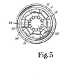
- FIG. 5 One embodiment particularly suited for viscous liquids is illustrated in FIG. 5.
- the members shown in FIG. 5 which correspond to similar previously described members are designated with corresponding primed numerals.
- ears 19' in FIG. 5 correspond to similar ears 19 in FIG. 3.
- the embodiment of FIG. 5 includes cylindrically shaped nibs 35 which are molded integrally with and project from ears 19' inwardly into aperture 33' when the spout is in its extended pouring orientation.
- Nibs 35 in combination with ears 19' define a central flow aperture 33' which has a dentated perimeter in the sense that the aperture has perimetrically located toothlike projections which extend inwardly. The dentated perimeter serves to break up any large bubble which might otherwise tend to pass whole through aperture 33'.
- nibs 35 need not be of the particular shape shown.
- nibs 35 could be triangularly or rectangularly shaped, and there could be more or fewer nibs per ear.
Landscapes
- Engineering & Computer Science (AREA)
- Mechanical Engineering (AREA)
- Closures For Containers (AREA)
- Details Of Rigid Or Semi-Rigid Containers (AREA)
- Containers Having Bodies Formed In One Piece (AREA)
Description
- This invention relates in general to nestable and extendable pouring spouts for containers and in particular to such spouts having a venting means for reducing pulsations in the outflowing liquid.
- There are a number of prior known nestable and extendable pouring spouts. Representative examples are shown in the following U.S. Patent Nos: 2,561,596 to Rieke, July 24, 1951; 2,565,699 to Rieke, August 28, 1951; 2,661,128 to Rieke, December 1, 1953; 2,895,654 to Rieke, July 21, 1959; 3,040,938 to Smith, June 26, 1962; 3,250,428 to Rieke, May 10, 1966; 3,604,740 to Summers, September 14, 1971; 3,613,966 to Summers, October 19, 1971; 3,804,305 to Rieke, April 16, 1974; and 4,295,583 to Schurr, October 20,1981.
- Of the above listed patents, Nos. 3,040,938 and 4,295,583 relate particularly to vented spouts. In many cases a smooth outflow of liquid from the spout of a container is particularly important. Examples are where it is desired to decant a precise amount of liquid from a large stock container into a smaller container or where the liquid is corrosive or toxic and splashing must therefore be avoided.
- Smooth, pulsation-free outflow may be obtained with a conventional spout by carefully controlling the angle of the spout with regard to the fluid level in the container so that the spout never flows full, thereby maintaining an air passageway through the spout into the container. One disadvantage of this method is that the required degree of control is often difficult to maintain, especially where the container is heavy. Another disadvantage is that only a fraction of the cross sectional area of the spout is available for fluid outflow when the container is near full, thus increasing the time necessary to decant the liquid.
- As a solution to the aforementioned problems, prior nestable and extendable spouts have been fitted with venting devices for maintaining an air passageway through the spout regardless of the angle of pouring, enabling venting of the container even though the opening of the container is completely submerged (see Smith, 3,040,938 and Schurr, 4,295,583). These prior venting devices are essentially tubes mounted concentrically within the neck of the spout so as to form an annular air space between the tube and the neck. The base of the tube is fitted with a flange having a plurality of small peripheral channels, which flange is drawn up against the base of the spout when the spout is in its extended orientation. In this orientation, air may enter the container through the annular space and the peripheral channels while the fluid exits through the central tube.
- Although the venting devices exemplified in Smith ('938) and Schurr ('583) function well, they have non-functional disadvantages associated with their structure. For instance, the venting device must be manufactured as a separate piece which is then mounted within the neck of the spout and secured thereto by welding or adhesive. This is a relatively expensive manufacturing process. Additionally, the venting device adds to the overall axial length of the spout when it is in its nested orientation, thus increasing the handling, packaging and shipping costs of such a spout.
- It would be desirable to provide a nestable and extendable pouring spout with a self contained venting means which may be inexpensively manufactured and which maintains the compact configuration of such spouts.
- Another example of a prior known nestable and extendable pouring spout is shown in German patent No. 1924824. This spout includes a deformable "bellows" part by means of which an outer socket end part may take up a nested orientation or an extended pouring orientation with respect to a base flange by means of which the spout is secured to the mouth of a container. The spout includes four projections which extend inwardly when the seal is in its extended orientation. The spout is intended to reduce splashing of contents when a container is righted, by means of the four projections. The projections do not touch or overlap. According to the invention there is provided a pouring spout for use with a container, comprising a spout having extending means for alternately disposing said spout in a nested orientation or in an extended pouring orientation;
- means for securing the pouring spout to the container; and
- a plurality of ears attached to the spout, which extend inwardly within the spout when the spout is disposed in the extended pouring orientation (see DE-C-1924824) characterised in that when the spout is disposed in the extended pouring orientation, the plurality of ears cooperates to define a central flow aperture for the outflow of liquid and each pair of adjacent ears defines a peripheral vent opening therebetween for the inflow of air, the cross-section of said central flow aperture being smaller than the interior flow cross-section of any subsequent spout outflow portion.
- One object of the present invention is to provide an improved self-venting nestable pouring spout which is compact and inexpensive to manufacture.
- One embodiment of the invention will now be described by way of example only and with reference to the accompanying drawings, in which:
- FIG. 1 is an elevation view in full section of one embodiment of the vented nestable pouring spout of the present invention, shown in its nested orientation.
- FIG. 2 is an elevation view in full section of the spout of FIG. 1, shown in its extended orientation.
- FIG. 3 is a bottom plan view of the spout of FIG. 2 in its extended orientation, particularly showing the venting structure.
- FIG. 4 is a top plan view of the spout of FIG. 1, particularly showing the tamper indicating seal.
- FIG. 5 is a bottom plan view of an alternate embodiment of a vented nestable pouring spout in its extended orientation, particularly showing the venting structure.
- Referring to Figs. 1 and 2, there is illustrated
nestable pouring spout 10 having as its principle components a mounting portion 11, abody portion 12, and aneck portion 13. In the preferred embodiment, mounting portion 11,body portion 12, andneck portion 13, together withears 19,seal 24 andpull ring 25 which are described below, are integrally molded from a low density flexible polyethylene plastic. - Mounting portion 11 is an annular U-shaped channel configured to mount on an
annular lip 14 which encompasses a generally circular opening in acontainer 20.Lip 14 may be made of plastic or metal.Anchor ring 15, which is preferably constructed of zinc plated steel, is crimped over mounting portion 11 to compress it about and secure it tolip 14, thereby effecting an air-tight, liquid-tight seal between mounting portion 11 andlip 14. -
Body portion 12 is a generally funnel shaped member which is secured at its larger circumferential edge to mounting portion 11 and at its smaller circumferential edge toneck portion 13.Body portion 12 includesinvertible fold portions body portion 12 to be generally S-shaped in section along a plane parallel to thelongitudinal axis 18 ofnestable pouring spout 10.Body portion 12 is substantially circular in cross-section along a plane perpendicular toaxis 18. Attached at the outside surface ofinvertible fold portion 16 is a plurality of circumferentially spacedears 19, each of which extends downwardly substantially parallel tolongitudinal axis 18 whennestable pouring spout 10 is in its nested orientation. In this orientation the ears do not restrict the opening of the container and do not interfere with the attainment of a fully nested orientation by the neck and body portions.Ears 19 provide a self-venting action forspout 10, which will be described in greater detail below. -
Neck portion 13 is a generally cylindricaltube having threads 21 near its upper end for threadedly receiving acap 23 havingcorresponding threads 22. Disposed within the opening ofneck portion 13 is a disk-like seal 24 having apull ring 25 attached proximate one edge ofseal 24.Seal 24 is provided with an annularperipheral groove 26 which provides a weakened point at whichseal 24 will break away whenpull ring 25 is pulled. -
Cap 23, which is preferably molded from a high density polyethylene plastic, includes integrally moldedflexible bail handles 27 which, whencap 23 is threadedly attached toneck portion 13, provide a convenient means forgrasping neck portion 13 and pulling it out into its extended orientation, as is shown in Fig. 2. - When
nestable pouring spout 10 is in its initial nested orientation prior to opening, there is disposed overcap 23 and neck portion 13 atamper indicating seal 28 which, if it is intact and undeformed, provides a quick visual indication that there has been no attempt to opennestable pouring spout 10. - A nestable pouring spout which is generally of the type shown herein, but without
ears 19, is more fully disclosed in United States Patent No. 3,619,966 issued to Summers on October 19, 1971, which disclosure is hereby incorporated by reference. - The user of a container having a
nestable pouring spout 10 mounted thereon first grasps pull-tab 29 on tamper indicating seal 28 (see Fig. 4), pulls the seal free and discards it. Bail handles 27 oncap 23 are then grasped and pulled in order to drawneck portion 13 out into its extended orientation.Cap 23 is then unscrewed and removed to gain access to seal 24. Pullring 25 is grasped by the user and pulled, causingseal 24 to break free alonggroove 26. The contents of the container can then be poured out andcap 23 can be screwed back ontoneck portion 13 to reseal the container in the event that the container is only partially emptied. - As
neck portion 13 is drawn outwardly,invertible fold portions body portion 12 invert such that the S-shaped curvature ofbody portion 12 is reversed whenneck portion 13 is in its fully extended orientation, as is shown in Fig. 2. In particular, asinvertible fold portion 16 inverts, eachear 19, which is securely attached thereto, will rotate inwardly substantially about its point of attachment. Whenneck portion 13 andbody portion 12 reach their fully extended orientations,ears 19 extend inwardly from mounting portion 11 substantially perpendicular tolongitudinal axis 18. - As is shown most clearly in Fig. 3, in the extended orientation of
spout 10,end portions 32 ofadjacent ears 19 are contiguous so as to define acentral flow aperture 33. In thisorientation ears 19 also define a plurality of generally triangularperipheral vent openings 34, one located between each pair ofadjacent ears 19. - Because
flow aperture 33 is of a somewhat smaller diameter than the interior diameter ofneck portion 13, the outward flow of liquid from the container does not fillneck portion 13. It should be noted that liquid will flow out of some of the submerged peripheral vent openings also, especially those at the lowest elevation for a particular pouring angle. Therefore, the area of the peripheral openings must be taken into account in determining the best relationship of the diameter ofaperture 33 to the diameter ofneck portion 13 to insure thatneck portion 13 does not flow full at any pouring angle. This insures that air may always enter throughneck portion 13, through the uppermostperipheral vent openings 34, and into the container, thereby equalizing the pressure within and without the container and permitting the smooth outflow of liquid. - The incoming air enters the container peripherally of the outflowing liquid stream so that the liquid stream is not interrupted and pulsation and splashing are kept to a minimum while permitting full flow through
flow aperture 33. Although the precise dynamics of the liquid and airflow are notfully understood, it is believed that the optimum ratio between the area of theperipheral vent openings 34 and thecentral aperture 33 is a function of the viscosity and surface tension characteristics of the liquid. - It has been observed that when high viscosity liquids are being decanted, a portion of the incoming air will pass through
central flow aperture 33. The air which enters throughaperture 33 tends to form large bubbles which span the diameter ofaperture 33, causing pulsations and discontinuities in the liquid outflow. This phenomenon may be partially controlled by increasing the area of each peripheral vent opening to enable a greater portion of the incoming air to pass through the peripheral vent openings rather than through the central flow aperture. One way to make each peripheral vent opening larger is to use a lesser number of ears. The area of each peripheral vent opening can also be increased by specially shaping the ears, such as by making each ear relatively narrow at its base where it is attached to the invertible fold, with each ear increasing in width toward its end portion. - One embodiment particularly suited for viscous liquids is illustrated in FIG. 5. The members shown in FIG. 5 which correspond to similar previously described members are designated with corresponding primed numerals. For example, ears 19' in FIG. 5 correspond to
similar ears 19 in FIG. 3. As shown, the embodiment of FIG. 5 includes cylindrically shapednibs 35 which are molded integrally with and project from ears 19' inwardly into aperture 33' when the spout is in its extended pouring orientation.Nibs 35 in combination with ears 19' define a central flow aperture 33' which has a dentated perimeter in the sense that the aperture has perimetrically located toothlike projections which extend inwardly. The dentated perimeter serves to break up any large bubble which might otherwise tend to pass whole through aperture 33'. By breaking up large bubbles into smaller bubbles, the outflow of liquid is made more nearly continuous with fewer and smaller pulsations. It is to be understood thatnibs 35 need not be of the particular shape shown. For example,nibs 35 could be triangularly or rectangularly shaped, and there could be more or fewer nibs per ear.
Claims (14)
Priority Applications (1)
| Application Number | Priority Date | Filing Date | Title |
|---|---|---|---|
| AT85301396T ATE42080T1 (en) | 1984-05-16 | 1985-02-28 | VENTED POURING SPOUT. |
Applications Claiming Priority (4)
| Application Number | Priority Date | Filing Date | Title |
|---|---|---|---|
| US06/610,688 US4555048A (en) | 1984-05-16 | 1984-05-16 | Vented nestable pouring spout |
| US610688 | 1984-05-16 | ||
| US06/643,070 US4618078A (en) | 1984-05-16 | 1984-08-22 | Vented nestable pouring spout |
| US643070 | 1996-04-30 |
Publications (3)
| Publication Number | Publication Date |
|---|---|
| EP0161746A2 EP0161746A2 (en) | 1985-11-21 |
| EP0161746A3 EP0161746A3 (en) | 1986-10-29 |
| EP0161746B1 true EP0161746B1 (en) | 1989-04-12 |
Family
ID=27086325
Family Applications (1)
| Application Number | Title | Priority Date | Filing Date |
|---|---|---|---|
| EP85301396A Expired EP0161746B1 (en) | 1984-05-16 | 1985-02-28 | Vented nestable pouring spout |
Country Status (12)
| Country | Link |
|---|---|
| US (1) | US4618078A (en) |
| EP (1) | EP0161746B1 (en) |
| JP (1) | JPH0714208Y2 (en) |
| AU (1) | AU578685B2 (en) |
| BR (1) | BR8500193A (en) |
| CA (1) | CA1240626A (en) |
| DE (2) | DE161746T1 (en) |
| ES (1) | ES292799Y (en) |
| GB (1) | GB2158814B (en) |
| HK (1) | HK40391A (en) |
| MX (1) | MX164975B (en) |
| SG (1) | SG29360G (en) |
Cited By (4)
| Publication number | Priority date | Publication date | Assignee | Title |
|---|---|---|---|---|
| EP1867574A1 (en) * | 2006-06-12 | 2007-12-19 | Rieke Corporation | A closure assembly having a spout with a memory band for spout directing |
| US7789277B2 (en) | 2006-06-12 | 2010-09-07 | Rieke Corporation | Closure assembly having a spout with a thicker band for spout directing |
| USD641628S1 (en) | 2010-11-17 | 2011-07-19 | Rieke Corporation | Closure for a container |
| US8292133B2 (en) | 2009-05-07 | 2012-10-23 | Rieke Corporation | Vented closure assembly for a container |
Families Citing this family (17)
| Publication number | Priority date | Publication date | Assignee | Title |
|---|---|---|---|---|
| DE3545548A1 (en) * | 1985-12-21 | 1987-07-02 | Berg Jacob Gmbh Co Kg | WARRANTY CLOSURE |
| DE3805648A1 (en) * | 1988-02-24 | 1989-09-07 | Berg Jacob Gmbh Co Kg | Pull-out pouring closure |
| DE8900736U1 (en) * | 1988-04-30 | 1989-03-30 | Stolz, Heinrich, 5908 Neunkirchen | Container with a closure incorporated into its top and covered by a sealing device |
| US5071037A (en) * | 1989-09-14 | 1991-12-10 | Graham Engineering Corporation | Blow molded bottle with integral pour spout |
| US5641099A (en) * | 1995-12-08 | 1997-06-24 | Rieke Corporation | Nestable pouring spout assembly |
| US5897823A (en) * | 1996-06-20 | 1999-04-27 | North America Packaging Corporation | Method of forming a plastic container component and the plastic container component formed by the method |
| US6106261A (en) * | 1998-08-31 | 2000-08-22 | John W. Von Holdt | Apparatus for molding a one-piece article in a single molding operation using two different plastic materials |
| CA2346114C (en) * | 1998-12-10 | 2008-02-19 | Ron Sturk | Flow vented and pressure vented closures |
| US6619518B1 (en) * | 2000-03-12 | 2003-09-16 | Jung Min Lee | Spout assembly for liquid container |
| US20070284398A1 (en) * | 2006-06-12 | 2007-12-13 | Baughman Gary M | Container closure assembly with extendable spout and tamper-evident portion |
| US7988007B2 (en) * | 2007-05-31 | 2011-08-02 | Rieke Corporation | Container closure and closing cap having contoured bail handles |
| CN101873973B (en) * | 2008-01-31 | 2011-11-23 | 大陆制罐株式会社 | Spout cap having two steps type straw part |
| US8113239B2 (en) * | 2009-05-07 | 2012-02-14 | David S. Smith America, Inc. | Vented valve assembly |
| US8814004B2 (en) | 2012-09-11 | 2014-08-26 | Letica Corporation | Tamper evident pull-out spout |
| US10173813B2 (en) | 2016-09-29 | 2019-01-08 | Dow Global Technologies Llc | Flexible container with pop-up spout |
| WO2021042018A1 (en) | 2019-08-29 | 2021-03-04 | Rieke Llc | Child resistant closure and spout combination |
| CN119486785A (en) * | 2022-05-04 | 2025-02-18 | 里克有限责任公司 | Flame-mitigating closure systems and containers |
Citations (1)
| Publication number | Priority date | Publication date | Assignee | Title |
|---|---|---|---|---|
| DE1924824C3 (en) * | 1969-05-16 | 1978-11-09 | Henkel Kgaa, 4000 Duesseldorf | Pull-out pouring cap |
Family Cites Families (21)
| Publication number | Priority date | Publication date | Assignee | Title |
|---|---|---|---|---|
| DE648664C (en) * | 1934-11-13 | 1937-08-06 | Arthur Nuetz | Double-walled outlet nozzle for liquid container |
| US2561596A (en) * | 1947-06-05 | 1951-07-24 | Rieke Metal Products Corp | Container nestable and contractible pouring spout |
| US2471172A (en) * | 1947-06-23 | 1949-05-24 | Stoller Daniel | Nipple and cap for baby nursing bottles |
| US2565699A (en) * | 1948-05-13 | 1951-08-28 | Rieke Metal Products Corp | Flexible, retractable dispensing spout |
| US2661128A (en) * | 1949-02-18 | 1953-12-01 | Rieke Metal Products Corp | Tamper and seal proof flexible pouring spout |
| US2840280A (en) * | 1954-05-11 | 1958-06-24 | American Flange & Mfg | Retractable rigid spouts and mountings therefor |
| US2804242A (en) * | 1955-07-07 | 1957-08-27 | John E Borah | Container spout and gasket combination |
| US2895654A (en) * | 1956-11-23 | 1959-07-21 | Rieke Metal Products Corp | Bail handled closure cap |
| US3040938A (en) * | 1958-02-17 | 1962-06-26 | Rieke Metal Products Corp | Vented pour spout |
| US3093273A (en) * | 1959-07-03 | 1963-06-11 | John E Borah | Retractable and extensible container spout |
| US3075676A (en) * | 1959-07-31 | 1963-01-29 | South Bend Modern Molding Inc | Container spout |
| US3091373A (en) * | 1961-04-25 | 1963-05-28 | Kirschenbaum Samuel | Whiskey pourer or similar device |
| US3250428A (en) * | 1964-03-09 | 1966-05-10 | Rieke Metal Products Corp | Means of attaching a closure to containers |
| US3604740A (en) * | 1969-02-04 | 1971-09-14 | Rieke Corp | Container closure combination |
| US3613966A (en) * | 1969-04-17 | 1971-10-19 | Rieke Corp | Nestable pouring spout with wall-supporting cap |
| US3717289A (en) * | 1971-02-25 | 1973-02-20 | American Flange & Mfg | Vented pouring spout |
| US3717324A (en) * | 1971-05-14 | 1973-02-20 | Volkswagenwerk Ag | Closure valve |
| US3804305A (en) * | 1973-08-01 | 1974-04-16 | Rieke Corp | Container closure with locking pull spout, and integral spout cap, pull ring, and outer seal |
| US4073413A (en) * | 1976-06-10 | 1978-02-14 | Tabler Herman L | Dispensing apparatus with self contained spout |
| US4295583A (en) * | 1979-08-09 | 1981-10-20 | Rieke Corporation | Closure cap vent |
| CA1215944A (en) * | 1982-06-03 | 1986-12-30 | Hugo Mueller | Nestable self-vent spout |
-
1984
- 1984-08-22 US US06/643,070 patent/US4618078A/en not_active Expired - Lifetime
-
1985
- 1985-01-09 CA CA000471724A patent/CA1240626A/en not_active Expired
- 1985-01-16 BR BR8500193A patent/BR8500193A/en not_active IP Right Cessation
- 1985-01-21 ES ES1985292799U patent/ES292799Y/en not_active Expired
- 1985-02-28 EP EP85301396A patent/EP0161746B1/en not_active Expired
- 1985-02-28 DE DE198585301396T patent/DE161746T1/en active Pending
- 1985-02-28 GB GB08505176A patent/GB2158814B/en not_active Expired
- 1985-02-28 DE DE8585301396T patent/DE3569361D1/en not_active Expired
- 1985-02-28 SG SG283/91A patent/SG29360G/en unknown
- 1985-05-02 AU AU41906/85A patent/AU578685B2/en not_active Expired
- 1985-05-03 MX MX205190A patent/MX164975B/en unknown
-
1991
- 1991-05-23 HK HK403/91A patent/HK40391A/en not_active IP Right Cessation
-
1992
- 1992-12-07 JP JP1992084113U patent/JPH0714208Y2/en not_active Expired - Lifetime
Patent Citations (1)
| Publication number | Priority date | Publication date | Assignee | Title |
|---|---|---|---|---|
| DE1924824C3 (en) * | 1969-05-16 | 1978-11-09 | Henkel Kgaa, 4000 Duesseldorf | Pull-out pouring cap |
Cited By (5)
| Publication number | Priority date | Publication date | Assignee | Title |
|---|---|---|---|---|
| EP1867574A1 (en) * | 2006-06-12 | 2007-12-19 | Rieke Corporation | A closure assembly having a spout with a memory band for spout directing |
| US7614530B2 (en) | 2006-06-12 | 2009-11-10 | Rieke Corporation | Closure assembly having a spout with a memory band for spout directing |
| US7789277B2 (en) | 2006-06-12 | 2010-09-07 | Rieke Corporation | Closure assembly having a spout with a thicker band for spout directing |
| US8292133B2 (en) | 2009-05-07 | 2012-10-23 | Rieke Corporation | Vented closure assembly for a container |
| USD641628S1 (en) | 2010-11-17 | 2011-07-19 | Rieke Corporation | Closure for a container |
Also Published As
| Publication number | Publication date |
|---|---|
| US4618078A (en) | 1986-10-21 |
| CA1240626A (en) | 1988-08-16 |
| SG29360G (en) | 1991-07-26 |
| ES292799U (en) | 1986-08-01 |
| EP0161746A2 (en) | 1985-11-21 |
| JPH0714208Y2 (en) | 1995-04-05 |
| GB2158814A (en) | 1985-11-20 |
| EP0161746A3 (en) | 1986-10-29 |
| AU4190685A (en) | 1985-11-21 |
| BR8500193A (en) | 1986-04-15 |
| US4618078B1 (en) | 1988-04-26 |
| DE3569361D1 (en) | 1989-05-18 |
| ES292799Y (en) | 1987-04-16 |
| GB2158814B (en) | 1987-07-22 |
| JPH063854U (en) | 1994-01-18 |
| MX164975B (en) | 1992-10-09 |
| AU578685B2 (en) | 1988-11-03 |
| HK40391A (en) | 1991-05-31 |
| DE161746T1 (en) | 1986-04-30 |
| GB8505176D0 (en) | 1985-04-03 |
Similar Documents
| Publication | Publication Date | Title |
|---|---|---|
| US4555048A (en) | Vented nestable pouring spout | |
| US4618078A (en) | Vented nestable pouring spout | |
| CA2346114C (en) | Flow vented and pressure vented closures | |
| EP1549557B1 (en) | Aerated rapid flow dispensing cap | |
| US4128189A (en) | Device for improving the pourability of fluids and also forming an improved closure for a container of such fluids | |
| US4273247A (en) | Bottle closure-cup assembly | |
| CA1128014A (en) | Closure cap vent | |
| US4969581A (en) | Unequivocal bottom delivery container with self-sealing valve | |
| US4294382A (en) | Container closure device | |
| US4762241A (en) | Container with supplemental opening for extracting contents | |
| US20200270030A1 (en) | Variable pour flow device | |
| US3310206A (en) | Pull-out spout assembly | |
| US5005726A (en) | Composite container assemblies | |
| JP2009505920A (en) | Liquid leakage prevention lid | |
| US4105141A (en) | Pouring device | |
| US4111331A (en) | Tamper-proof closure device | |
| CA1122575A (en) | Pouring mechanism in a container for liquids which has a tubular pouring spout | |
| CA1248053A (en) | Containers | |
| IE831301L (en) | Self-venting flexible pouring spouts for containers | |
| US2848142A (en) | Container | |
| US20070017940A1 (en) | Container with a non-drip pouring lip | |
| US20250236438A1 (en) | Pouring Spout | |
| WO2006110938A1 (en) | Pouring aid | |
| GB2091677A (en) | Container spouts | |
| JP2509126Y2 (en) | Container with pouring tap |
Legal Events
| Date | Code | Title | Description |
|---|---|---|---|
| PUAI | Public reference made under article 153(3) epc to a published international application that has entered the european phase |
Free format text: ORIGINAL CODE: 0009012 |
|
| AK | Designated contracting states |
Designated state(s): AT BE CH DE FR GB IT LI LU NL SE |
|
| EL | Fr: translation of claims filed | ||
| TCAT | At: translation of patent claims filed | ||
| DET | De: translation of patent claims | ||
| PUAL | Search report despatched |
Free format text: ORIGINAL CODE: 0009013 |
|
| AK | Designated contracting states |
Kind code of ref document: A3 Designated state(s): AT BE CH DE FR GB IT LI LU NL SE |
|
| 17P | Request for examination filed |
Effective date: 19870424 |
|
| 17Q | First examination report despatched |
Effective date: 19880208 |
|
| GRAA | (expected) grant |
Free format text: ORIGINAL CODE: 0009210 |
|
| AK | Designated contracting states |
Kind code of ref document: B1 Designated state(s): AT BE CH DE FR GB IT LI LU NL SE |
|
| REF | Corresponds to: |
Ref document number: 42080 Country of ref document: AT Date of ref document: 19890415 Kind code of ref document: T |
|
| ITF | It: translation for a ep patent filed | ||
| REF | Corresponds to: |
Ref document number: 3569361 Country of ref document: DE Date of ref document: 19890518 |
|
| ET | Fr: translation filed | ||
| PLBI | Opposition filed |
Free format text: ORIGINAL CODE: 0009260 |
|
| 26 | Opposition filed |
Opponent name: JACOB BERG GMBH & CO. KG, Effective date: 19891221 |
|
| NLR1 | Nl: opposition has been filed with the epo |
Opponent name: JACOB BERG GMBH & CO. KG. |
|
| ITTA | It: last paid annual fee | ||
| PLBM | Termination of opposition procedure: date of legal effect published |
Free format text: ORIGINAL CODE: 0009276 |
|
| STAA | Information on the status of an ep patent application or granted ep patent |
Free format text: STATUS: OPPOSITION PROCEDURE CLOSED |
|
| 27C | Opposition proceedings terminated |
Effective date: 19911110 |
|
| REG | Reference to a national code |
Ref country code: FR Ref legal event code: CL |
|
| EPTA | Lu: last paid annual fee | ||
| NLR2 | Nl: decision of opposition | ||
| EAL | Se: european patent in force in sweden |
Ref document number: 85301396.9 |
|
| REG | Reference to a national code |
Ref country code: GB Ref legal event code: IF02 |
|
| PGFP | Annual fee paid to national office [announced via postgrant information from national office to epo] |
Ref country code: AT Payment date: 20040203 Year of fee payment: 20 |
|
| PGFP | Annual fee paid to national office [announced via postgrant information from national office to epo] |
Ref country code: NL Payment date: 20040205 Year of fee payment: 20 |
|
| PGFP | Annual fee paid to national office [announced via postgrant information from national office to epo] |
Ref country code: FR Payment date: 20040210 Year of fee payment: 20 |
|
| PGFP | Annual fee paid to national office [announced via postgrant information from national office to epo] |
Ref country code: SE Payment date: 20040219 Year of fee payment: 20 |
|
| PGFP | Annual fee paid to national office [announced via postgrant information from national office to epo] |
Ref country code: GB Payment date: 20040225 Year of fee payment: 20 |
|
| PGFP | Annual fee paid to national office [announced via postgrant information from national office to epo] |
Ref country code: LU Payment date: 20040226 Year of fee payment: 20 |
|
| PGFP | Annual fee paid to national office [announced via postgrant information from national office to epo] |
Ref country code: CH Payment date: 20040227 Year of fee payment: 20 |
|
| PGFP | Annual fee paid to national office [announced via postgrant information from national office to epo] |
Ref country code: DE Payment date: 20040311 Year of fee payment: 20 |
|
| PGFP | Annual fee paid to national office [announced via postgrant information from national office to epo] |
Ref country code: BE Payment date: 20040323 Year of fee payment: 20 |
|
| PG25 | Lapsed in a contracting state [announced via postgrant information from national office to epo] |
Ref country code: GB Free format text: LAPSE BECAUSE OF EXPIRATION OF PROTECTION Effective date: 20050227 Ref country code: CH Free format text: LAPSE BECAUSE OF EXPIRATION OF PROTECTION Effective date: 20050227 Ref country code: LI Free format text: LAPSE BECAUSE OF EXPIRATION OF PROTECTION Effective date: 20050227 |
|
| BE20 | Be: patent expired |
Owner name: *RIEKE CORP. Effective date: 20050228 |
|
| PG25 | Lapsed in a contracting state [announced via postgrant information from national office to epo] |
Ref country code: NL Free format text: LAPSE BECAUSE OF EXPIRATION OF PROTECTION Effective date: 20050228 Ref country code: LU Free format text: LAPSE BECAUSE OF EXPIRATION OF PROTECTION Effective date: 20050228 |
|
| REG | Reference to a national code |
Ref country code: GB Ref legal event code: PE20 |
|
| REG | Reference to a national code |
Ref country code: CH Ref legal event code: PL |
|
| NLV7 | Nl: ceased due to reaching the maximum lifetime of a patent |
Effective date: 20050228 |
|
| EUG | Se: european patent has lapsed | ||
| BE20 | Be: patent expired |
Owner name: *RIEKE CORP. Effective date: 20050228 |