EP0161037A2 - Method and apparatus for welding - Google Patents
Method and apparatus for welding Download PDFInfo
- Publication number
- EP0161037A2 EP0161037A2 EP85300160A EP85300160A EP0161037A2 EP 0161037 A2 EP0161037 A2 EP 0161037A2 EP 85300160 A EP85300160 A EP 85300160A EP 85300160 A EP85300160 A EP 85300160A EP 0161037 A2 EP0161037 A2 EP 0161037A2
- Authority
- EP
- European Patent Office
- Prior art keywords
- workpiece
- welding
- weld
- high energy
- weld zone
- Prior art date
- Legal status (The legal status is an assumption and is not a legal conclusion. Google has not performed a legal analysis and makes no representation as to the accuracy of the status listed.)
- Granted
Links
Images



Classifications
-
- B—PERFORMING OPERATIONS; TRANSPORTING
- B23—MACHINE TOOLS; METAL-WORKING NOT OTHERWISE PROVIDED FOR
- B23K—SOLDERING OR UNSOLDERING; WELDING; CLADDING OR PLATING BY SOLDERING OR WELDING; CUTTING BY APPLYING HEAT LOCALLY, e.g. FLAME CUTTING; WORKING BY LASER BEAM
- B23K15/00—Electron-beam welding or cutting
- B23K15/0046—Welding
- B23K15/008—Spot welding
-
- B—PERFORMING OPERATIONS; TRANSPORTING
- B23—MACHINE TOOLS; METAL-WORKING NOT OTHERWISE PROVIDED FOR
- B23K—SOLDERING OR UNSOLDERING; WELDING; CLADDING OR PLATING BY SOLDERING OR WELDING; CUTTING BY APPLYING HEAT LOCALLY, e.g. FLAME CUTTING; WORKING BY LASER BEAM
- B23K26/00—Working by laser beam, e.g. welding, cutting or boring
- B23K26/08—Devices involving relative movement between laser beam and workpiece
- B23K26/10—Devices involving relative movement between laser beam and workpiece using a fixed support, i.e. involving moving the laser beam
-
- B—PERFORMING OPERATIONS; TRANSPORTING
- B23—MACHINE TOOLS; METAL-WORKING NOT OTHERWISE PROVIDED FOR
- B23K—SOLDERING OR UNSOLDERING; WELDING; CLADDING OR PLATING BY SOLDERING OR WELDING; CUTTING BY APPLYING HEAT LOCALLY, e.g. FLAME CUTTING; WORKING BY LASER BEAM
- B23K26/00—Working by laser beam, e.g. welding, cutting or boring
- B23K26/20—Bonding
- B23K26/21—Bonding by welding
- B23K26/22—Spot welding
Definitions
- the present invention relates to method and apparatus for welding.
- Welds of the type suggested in the present application were generally accomplished by means of electric resistance-welding techniques.
- electrodes are applied to the weld zone with pressure in order to compress the overlapping layers of metal in the weld zone.
- electric power to the electrodes current flows across the joint through the overlapping metal layers. Since the resistance is high at the interface of the layers, welding temperatures Day be achieved and a weld nugget is formed at the joint.
- the weld therefore is interior to the layers and cannot be visually inspected.
- One example of a test which is used to inspect the integrity of the resistance-welded joint for quality control is the "peel" test.
- a sample of the workpiece is joined by a single spot utilizing the same procedures as applied in a production operation for a finished part. After welding, one side of the joined sample is clamped and the other is peeled off.
- the weld button may then be examined to determine the parameters of the fused zone. Although this information may then be applied to the production cycle, it is clear that an accurate correlation depends on the ability to accurately control and monitor theoperation.
- a laser beam is an intense, highly coherent beam of monochromatic light which has been amplified many times. Since the beam is exceptionally intense, extremely narrow and highly coherent, it may be focussed to an image that is brighter than the original source. In this way it is possible to obtain a light source so intense it can fuse steel and other metals to form a weld.
- the beam may also be optically deflected for accurate placement of the weld zone. The use of inert gas shielding in the work zone will improve the quality of the weld.
- laser welding provides deeper penetration and is very suitable for delicate work. It is also a rapid, precise and highly controllable process which creates exceptionally high quality welds.
- a laser welding process generally requires less heat input than resistance-welding with a reduction in distortion.
- a first aspect of the invention provides apparatus for welding a metal workpiece, comprising: clamping means for exerting a compressive force on the workpiece during the welding operation in the zone within which the weld is to be performed; means for generating a high energy beam and applying said beam to the workpiece in the weld zone with sufficient power to fuse the workpiece and create a weld; and means to control the application of the beam to the workpiece to create a substantially spiral-shaped weld pattern.
- a second aspect of the invention provides a method of welding a metal workpiece within a predetermined weld zone, comprising the steps of: applying a compressive force on the workpiece in the weld zone; generating a high energy beam having sufficient power to fuse the workpiece and create a weld; applying the high energy beam to the workpiece within the weld zone; and moving the high energy beam through a substantially spiral-shaped pattern in the weld zone.
- a third aspect of the invention provides apparatus for welding a metal workpiece having first and second sides, comprising: a supporting structure extending to either side of the workpiece; a ram mounted on the supporting structure adjacent the second side of the workpiece and being operable to exert a force towards said workpiece; a first clamping element mounted on the supporting structure for engagement with said first side of said workpiece, said first clamping element having an axial passage extending therethrough; a second clamping element mounted on the ram to engage the second side of said workpiece and exert a compressive force on the workpiece in conjunction with the first clamping element; means mounted on the supporting structure for generating a high energy beam and applying said beam through the axial passage of the first clamping element to the workpiece in the weld zone with sufficient power to fuse the workpiece and create a weld; and means to control the application of the beam to the workpiece to create a predetermined weld pattern.
- a workpiece consisting of multiple layers of metal is welded together by means of a laser to form an integral assembly.
- the layers are compressed in the weld zone by the engagement of the workpiece between upper and lower clamping elements.
- the clamping elements are tubular in shape having an axial passage.
- the laser beam is applied to the workpiece through the axial passage of one of the tubular clamping elements.
- the axial passage of each clamping element is filled with inert gas to displace air and to provide an oxygen-free weld zone.
- a welding system is comprised of a laser beam generator 1, a pair of clamping elements 2 and 3, and means to create a spiral pattern 4.
- the laser beam generator 1 may be any commercially available unit, for example, a C0 2 laser which generates between 600 watts to 2000 watts continuously or up to 3000 watts in pulses.
- the pattern generating system consists of optical deflection means 5 which is controlled by computer 6.
- the computer 6 is programmed to move the beam in a substantially spiral pattern. This requires consideration of the linear speed of travel, the overall size of the pattern and the changing radius of the pattern. For ease in programming, it may be necessary to approximate the spiral pattern, for example, by using interconnected circular sections of increasing radius.
- the ideal pattern as approximated by the pattern shown in Figure 4, is based on the archimedian spiral, the characteristics of which may be represented as follows.
- Clamping elements 2 and 3 are provided to compress the workpiece in the weld zone.
- lower clamping element 3 is movable upward to engage the workpiece and force it against clamping element 2.
- the movement may be accomplished by a pneumatic or hydraulic ram 7 as is well-known in the field of resistance-welding.
- the ram 7 is secured to the support frame 12 and should becapable of supplying a force of 50 to 400 lbs. in the weld zone.
- the clamping assembly consists of a pair of upper tubular members 8 and 9 and a pair of lower tubular members 10 and 11, each having axial passages 17 and 18.
- the outer members 8 and 10 of each pair are fixed to the rigid support frame 12 and the hydraulic ram 7 respectively and are constructed with internal threads 13.
- the inner tubular members 9 and 11 of each pair have external threads 14 which mate with the internal threads 13 of outer members 8 and 10. In this manner the tubular members 9 and 11 may be removably secured in the assembled position.
- fluid fittings 15 are attached to the inner members 9 and 11 to allow the supply of an inert gas, such as argon, to the weld zone.
- the laser beam generator 1 operates in conjunction with the upper clamping members 8 and 9 to enable the laser beam to be fired through the axial passage 17.
- This passage 17 must be large enough to allow deflection of the beam through the spiral pattern.
- the interface between lower tubular member 9 and the workpiece substantially defines the weld zone.
- the laser beam generator 1 is held stationary and the workpiece is mounted and registered on an x-y table 16 by the clamping elements 2 and 3.
- the x-y table may be numerically controlled and programmed through computer 6 to move the workpiece under the laser beam in a substantially spiral pattern.
- a nozzle 15 is attached to a supply of inert gas and provides a substantially oxygen-free atmosphere in the weld zone.
- the machine By designing the machine to resemble traditional resistance-welding equipment and by utilizing pneumatic actuation of the clamping mechanism, coordinated with the computer controlled laser pattern generating system, the learning cycle for operators of the equipment will be substantially reduced and the process will be readily adaptable to any resistance-welding operation.
- the workpiece is first registered within the clamping elements 2 and 3 so that the weld zone is underneath the tubular clamping member 9 and the ram 7 is actuated to cause clamping elements 2 and 3 to exert a clamping force of approximately 50 to 400 lbs. in the weld zone.
- the laser 1 is then fired through the upper tubular assembly passage 18 with sufficient power to fully penetrate the workpiece at a specific linear rate of movement.
- the optical deflection system 5 is then actuated to move the laser beam at a constant linear speed through a spiral pattern. In order to avoid hot stop, crater cracks, the linear speed should be accelerated at the end of the pattern as shown in Figure 4.
- an inert gas bath is applied to the weld zone through both upper and lower tubular members 9 and 11. After the clamping elements 2 and 3 are released, the workpiece is moved to the next weld zone.
Landscapes
- Engineering & Computer Science (AREA)
- Physics & Mathematics (AREA)
- Optics & Photonics (AREA)
- Mechanical Engineering (AREA)
- Plasma & Fusion (AREA)
- Laser Beam Processing (AREA)
- Welding Or Cutting Using Electron Beams (AREA)
Abstract
Description
- The present invention relates to method and apparatus for welding.
- Welds of the type suggested in the present application were generally accomplished by means of electric resistance-welding techniques. In these methods, electrodes are applied to the weld zone with pressure in order to compress the overlapping layers of metal in the weld zone. By applying electric power to the electrodes current flows across the joint through the overlapping metal layers. Since the resistance is high at the interface of the layers, welding temperatures Day be achieved and a weld nugget is formed at the joint.
- The weld therefore is interior to the layers and cannot be visually inspected. One example of a test which is used to inspect the integrity of the resistance-welded joint for quality control is the "peel" test. In this test, a sample of the workpiece is joined by a single spot utilizing the same procedures as applied in a production operation for a finished part. After welding, one side of the joined sample is clamped and the other is peeled off. The weld button may then be examined to determine the parameters of the fused zone. Although this information may then be applied to the production cycle, it is clear that an accurate correlation depends on the ability to accurately control and monitor theoperation. Since this method of welding is used for large volume, repetitive, production work in which one machine can be set up to make thousands of similar joints, close control and monitoring of the conditions of the weld zone are not always possible. The operator is, therefore, required to take frequent samples and perform the destructive "peel" test.
- The disadvantages of resistance-welding, apart from the difficulty of inspection and process control, are that it requires a high heat input which creates thermal distortions on the workpiece.
- Welding operations utilizing a laser beam as the energy source are becoming more prevalent in the production environment. A laser beam is an intense, highly coherent beam of monochromatic light which has been amplified many times. Since the beam is exceptionally intense, extremely narrow and highly coherent, it may be focussed to an image that is brighter than the original source. In this way it is possible to obtain a light source so intense it can fuse steel and other metals to form a weld. The beam may also be optically deflected for accurate placement of the weld zone. The use of inert gas shielding in the work zone will improve the quality of the weld.
- Similar to electron beam techniques, laser welding provides deeper penetration and is very suitable for delicate work. It is also a rapid, precise and highly controllable process which creates exceptionally high quality welds. A laser welding process generally requires less heat input than resistance-welding with a reduction in distortion.
- It is the purpose of this invention to provide a welding process utilizing a laser or other high energy beam which is as simple and repeatable as a resistance- weld process -änd creates a high strength weld that may be easily inspected.
- A first aspect of the invention provides apparatus for welding a metal workpiece, comprising: clamping means for exerting a compressive force on the workpiece during the welding operation in the zone within which the weld is to be performed; means for generating a high energy beam and applying said beam to the workpiece in the weld zone with sufficient power to fuse the workpiece and create a weld; and means to control the application of the beam to the workpiece to create a substantially spiral-shaped weld pattern.
- A second aspect of the invention provides a method of welding a metal workpiece within a predetermined weld zone, comprising the steps of: applying a compressive force on the workpiece in the weld zone; generating a high energy beam having sufficient power to fuse the workpiece and create a weld; applying the high energy beam to the workpiece within the weld zone; and moving the high energy beam through a substantially spiral-shaped pattern in the weld zone.
- A third aspect of the invention provides apparatus for welding a metal workpiece having first and second sides, comprising: a supporting structure extending to either side of the workpiece; a ram mounted on the supporting structure adjacent the second side of the workpiece and being operable to exert a force towards said workpiece; a first clamping element mounted on the supporting structure for engagement with said first side of said workpiece, said first clamping element having an axial passage extending therethrough; a second clamping element mounted on the ram to engage the second side of said workpiece and exert a compressive force on the workpiece in conjunction with the first clamping element; means mounted on the supporting structure for generating a high energy beam and applying said beam through the axial passage of the first clamping element to the workpiece in the weld zone with sufficient power to fuse the workpiece and create a weld; and means to control the application of the beam to the workpiece to create a predetermined weld pattern.
- In the invention, a workpiece consisting of multiple layers of metal is welded together by means of a laser to form an integral assembly. The layers are compressed in the weld zone by the engagement of the workpiece between upper and lower clamping elements. The clamping elements are tubular in shape having an axial passage. The laser beam is applied to the workpiece through the axial passage of one of the tubular clamping elements. The axial passage of each clamping element is filled with inert gas to displace air and to provide an oxygen-free weld zone. By either deflecting the laser beam or moving the workpiece through a predetermined pattern, a substantially spiral-shaped weld pattern is produced. This movement is computer controlled so that the weld pattern is a composite of fused and unaffected material and extends completely through the metal layers of the workpiece.
- Other preferred features are as set forth in the accompanying claims.
- The invention will be further described by way of example with reference to the accompanying drawings, in which:
- Figure 1 is a schematic diagram of the laser welding system of this invention having a computer controlled optical deflection system;
- Figure la is an end view of a tubular member of the apparatus of Figure 1, showing inert gas jets;
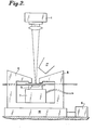
- Figure 2 is a schematic diagram of the laser welding system of the present invention having the workpiece mounted on a computer controlled x-y table;
- Figure 3 shows a prior art electric resistance-welding technique;
- Figure 4 is a top view of the substantially spiral-shaped weld pattern of the present invention; and
- Figure 5 is a bottom view of the substantially spiral-shaped weld pattern of the present invention.
- Figure 6 is a chart showing the relative strengths of welds performed by prior art resistance-welding techniques and spiral pattern welds performed according the present invention.
- A welding system according to the invention is comprised of a laser beam generator 1, a pair of
clamping elements - In the preferred embodiment shown in Figure 1, the laser beam generator 1 may be any commercially available unit, for example, a C02 laser which generates between 600 watts to 2000 watts continuously or up to 3000 watts in pulses.
- In the system of Figure 1, the pattern generating system consists of optical deflection means 5 which is controlled by
computer 6. Thecomputer 6 is programmed to move the beam in a substantially spiral pattern. This requires consideration of the linear speed of travel, the overall size of the pattern and the changing radius of the pattern. For ease in programming, it may be necessary to approximate the spiral pattern, for example, by using interconnected circular sections of increasing radius. - The ideal pattern, as approximated by the pattern shown in Figure 4, is based on the archimedian spiral, the characteristics of which may be represented as follows.
- r = radius of spiral = a 6 where 9 = angle of spiral rotation and

- r(2) = the radius of the spiral at e = 2 π
- Since S = linear travel speed which is kept constant and is approximately equal to


- This indicates that both the rate of angular rotation and the rate of increase in the radius are decreasing as the spiral unwinds. For example, if the final size of the weld pattern is to be 0.25 inches in diameter, and the distance between spiral arms is 0.040 inches, slightly more than three spiral revolutions can be used, as shown in Figure 4. Linear travel speeds (S) of 50 to 200 inches per minute will be desirable.
- In order to maintain good weld characteristics and provide a weld that may be easily monitored by visual inspection, full penetration through the entire workpiece is desirable, as shown in Figure 5. Clamping
elements lower clamping element 3 is movable upward to engage the workpiece and force it against clampingelement 2. The movement may be accomplished by a pneumatic orhydraulic ram 7 as is well-known in the field of resistance-welding. Theram 7 is secured to thesupport frame 12 and should becapable of supplying a force of 50 to 400 lbs. in the weld zone. - The clamping assembly consists of a pair of upper tubular members 8 and 9 and a pair of lower
tubular members axial passages outer members 8 and 10 of each pair are fixed to therigid support frame 12 and thehydraulic ram 7 respectively and are constructed withinternal threads 13. The innertubular members 9 and 11 of each pair haveexternal threads 14 which mate with theinternal threads 13 ofouter members 8 and 10. In this manner thetubular members 9 and 11 may be removably secured in the assembled position. As shown in Figure la,fluid fittings 15 are attached to theinner members 9 and 11 to allow the supply of an inert gas, such as argon, to the weld zone. - As shown in Figure 1, the laser beam generator 1 operates in conjunction with the upper clamping members 8 and 9 to enable the laser beam to be fired through the
axial passage 17. Thispassage 17 must be large enough to allow deflection of the beam through the spiral pattern. The interface between lower tubular member 9 and the workpiece substantially defines the weld zone. - In an alternate embodiment shown in Figure 2, the laser beam generator 1 is held stationary and the workpiece is mounted and registered on an x-y table 16 by the
clamping elements computer 6 to move the workpiece under the laser beam in a substantially spiral pattern. Anozzle 15 is attached to a supply of inert gas and provides a substantially oxygen-free atmosphere in the weld zone. - By designing the machine to resemble traditional resistance-welding equipment and by utilizing pneumatic actuation of the clamping mechanism, coordinated with the computer controlled laser pattern generating system, the learning cycle for operators of the equipment will be substantially reduced and the process will be readily adaptable to any resistance-welding operation.
- To operate the system of Figure 1, the workpiece is first registered within the
clamping elements ram 7 is actuated to causeclamping elements tubular assembly passage 18 with sufficient power to fully penetrate the workpiece at a specific linear rate of movement. Theoptical deflection system 5 is then actuated to move the laser beam at a constant linear speed through a spiral pattern. In order to avoid hot stop, crater cracks, the linear speed should be accelerated at the end of the pattern as shown in Figure 4. During fusion of the workpiece material, an inert gas bath is applied to the weld zone through both upper and lowertubular members 9 and 11. After theclamping elements - It has been found that by use of the spiral pattern, an increase of almost 50% in weld strength is achieved. This is accomplished with a reduction of about 80% in actual weld area and a significant decrease in total heat energy input. Although the use of a laser is anticipated, similar results can be obtained with an electron beam welder as shown in the chart of Figure 6. Because the molten metal expulsion encountered in resistance-welding is eliminated, the parts of the workpiece need not be overlapped as much as required in resistance-welding; only an overlap sufficient to accommodate the spiral pattern need be present. In addition, an increase in the maximum ratio of the thicknesses of the parts of the workpiece is achieved to approximately 20:1 from the 3:1 limit present in resistance-welding.
Claims (28)
Applications Claiming Priority (2)
| Application Number | Priority Date | Filing Date | Title |
|---|---|---|---|
| US605936 | 1984-05-01 | ||
| US06/605,936 US4658110A (en) | 1984-05-01 | 1984-05-01 | Method and apparatus for welding |
Publications (3)
| Publication Number | Publication Date |
|---|---|
| EP0161037A2 true EP0161037A2 (en) | 1985-11-13 |
| EP0161037A3 EP0161037A3 (en) | 1986-01-22 |
| EP0161037B1 EP0161037B1 (en) | 1988-12-28 |
Family
ID=24425831
Family Applications (1)
| Application Number | Title | Priority Date | Filing Date |
|---|---|---|---|
| EP85300160A Expired EP0161037B1 (en) | 1984-05-01 | 1985-01-10 | Method and apparatus for welding |
Country Status (6)
| Country | Link |
|---|---|
| US (1) | US4658110A (en) |
| EP (1) | EP0161037B1 (en) |
| JP (1) | JPS60234786A (en) |
| BR (1) | BR8500345A (en) |
| CA (1) | CA1227542A (en) |
| DE (1) | DE3566966D1 (en) |
Cited By (3)
| Publication number | Priority date | Publication date | Assignee | Title |
|---|---|---|---|---|
| EP0558870B1 (en) * | 1992-03-02 | 1997-05-14 | Sulzer Innotec Ag | Free welding of metal structures casing a laser |
| GB2342881A (en) * | 1998-09-26 | 2000-04-26 | Univ Coventry | Welding |
| CN105855706A (en) * | 2015-02-09 | 2016-08-17 | 司浦爱激光技术英国有限公司 | laser weld |
Families Citing this family (23)
| Publication number | Priority date | Publication date | Assignee | Title |
|---|---|---|---|---|
| US4847467A (en) * | 1988-08-19 | 1989-07-11 | Colt 7 Inc. | Laser welding clamp |
| US5090612A (en) * | 1991-02-13 | 1992-02-25 | Globe-Union Inc. | Method of fabricating a pressure vessel for a metal oxide-hydrogen battery |
| US5160822A (en) * | 1991-05-14 | 1992-11-03 | General Electric Company | Method for depositing material on the tip of a gas turbine engine airfoil using linear translational welding |
| US5304200A (en) * | 1991-05-29 | 1994-04-19 | Cordis Corporation | Welded radially expandable endoprosthesis and the like |
| US5187345A (en) * | 1991-11-22 | 1993-02-16 | The Torrington Company | Method of welding retainer rings |
| US5290989A (en) * | 1993-02-23 | 1994-03-01 | The United States Of America As Represented By The Secretary Of The Air Force | Weld root shield device and method |
| GB2281865B (en) * | 1993-09-16 | 1997-07-30 | Cordis Corp | Endoprosthesis having multiple laser welded junctions,method and procedure |
| US5591358A (en) * | 1994-03-23 | 1997-01-07 | Progressive Tool & Industries Co. | Apparatus for clamping and laser welding |
| DE19501866C2 (en) * | 1995-01-23 | 2003-06-12 | Audi Ag | Device for connecting sheet metal components by welding |
| DE19831558C1 (en) * | 1998-07-14 | 2000-03-30 | Siemens Ag | Device for laser processing flat workpieces |
| US8632590B2 (en) | 1999-10-20 | 2014-01-21 | Anulex Technologies, Inc. | Apparatus and methods for the treatment of the intervertebral disc |
| JP2004098122A (en) * | 2002-09-09 | 2004-04-02 | Futaba Industrial Co Ltd | Laser welding method |
| US20040266539A1 (en) * | 2003-06-27 | 2004-12-30 | Delco Remy America, Inc., A Delaware Corporation | Laser staked two-piece drive shaft for a starter motor |
| US20060027541A1 (en) * | 2004-08-03 | 2006-02-09 | Sun Peter C | Programmable non-contact fusion welding apparatus and method |
| US7823272B2 (en) * | 2006-11-14 | 2010-11-02 | The Gillette Company | Systems for producing assemblies |
| KR101180916B1 (en) * | 2007-11-20 | 2012-09-07 | 삼성테크윈 주식회사 | Apparatus for bonding camera module, equipment for assembling camera module having the same and method for assembling camera module using the same |
| US9856820B2 (en) | 2010-10-05 | 2018-01-02 | Mahle International Gmbh | Piston assembly |
| US8973484B2 (en) | 2011-07-01 | 2015-03-10 | Mahle Industries Inc. | Piston with cooling gallery |
| EP3112077B1 (en) * | 2014-02-25 | 2021-03-31 | Panasonic Intellectual Property Management Co., Ltd. | Laser welding method |
| US10118249B2 (en) | 2015-10-15 | 2018-11-06 | GM Global Technology Operations LLC | Laser beam welding with a spiral weld path having a first order of continuity |
| CN108778608B (en) * | 2016-03-15 | 2020-11-17 | 杰富意钢铁株式会社 | Lap joint laser welded joint, method for manufacturing welded joint, and automobile frame member |
| DE102018102523B4 (en) * | 2018-02-05 | 2019-10-10 | Scansonic Mi Gmbh | Welding method and laser welding device for joining foil-like workpieces |
| WO2020045263A1 (en) * | 2018-08-30 | 2020-03-05 | ローム株式会社 | Joined structure, semiconductor device, and joining method |
Family Cites Families (7)
| Publication number | Priority date | Publication date | Assignee | Title |
|---|---|---|---|---|
| US3437785A (en) * | 1966-05-06 | 1969-04-08 | Welding Research Inc | Method for electron beam welding of overlapped sheets |
| GB1271662A (en) * | 1968-09-23 | 1972-04-26 | Lucas Industries Ltd | Electron beam welding |
| IT1077304B (en) * | 1976-06-23 | 1985-05-04 | Eaton Corp | REGULATOR FOR DEVICES OPERATED BY THE PRESSURE OF A FLUID |
| US4263496A (en) * | 1978-06-16 | 1981-04-21 | Rolls-Royce Limited | Method of welding by electron beam |
| JPS5868492A (en) * | 1981-10-19 | 1983-04-23 | Toshiba Corp | Laser spot welder |
| JPS5868491A (en) * | 1981-10-19 | 1983-04-23 | Toshiba Corp | Laser spot welder |
| US4461947A (en) * | 1982-08-24 | 1984-07-24 | Allied Corporation | Rotating laser beam with coincident gas jet |
-
1984
- 1984-05-01 US US06/605,936 patent/US4658110A/en not_active Expired - Lifetime
- 1984-12-12 JP JP59260983A patent/JPS60234786A/en active Granted
-
1985
- 1985-01-09 CA CA000471754A patent/CA1227542A/en not_active Expired
- 1985-01-10 EP EP85300160A patent/EP0161037B1/en not_active Expired
- 1985-01-10 DE DE8585300160T patent/DE3566966D1/en not_active Expired
- 1985-01-25 BR BR8500345A patent/BR8500345A/en not_active IP Right Cessation
Cited By (6)
| Publication number | Priority date | Publication date | Assignee | Title |
|---|---|---|---|---|
| EP0558870B1 (en) * | 1992-03-02 | 1997-05-14 | Sulzer Innotec Ag | Free welding of metal structures casing a laser |
| GB2342881A (en) * | 1998-09-26 | 2000-04-26 | Univ Coventry | Welding |
| GB2342881B (en) * | 1998-09-26 | 2003-04-23 | Univ Coventry | Welding |
| CN105855706A (en) * | 2015-02-09 | 2016-08-17 | 司浦爱激光技术英国有限公司 | laser weld |
| WO2016128704A3 (en) * | 2015-02-09 | 2016-11-24 | Spi Lasers Uk Limited | Method of laser welding employing a pattern of micro welds |
| US12392367B2 (en) | 2015-02-09 | 2025-08-19 | Trumpf Laser Uk Limited | Method for laser microwelding |
Also Published As
| Publication number | Publication date |
|---|---|
| BR8500345A (en) | 1986-04-15 |
| DE3566966D1 (en) | 1989-02-02 |
| EP0161037B1 (en) | 1988-12-28 |
| US4658110A (en) | 1987-04-14 |
| JPS60234786A (en) | 1985-11-21 |
| EP0161037A3 (en) | 1986-01-22 |
| CA1227542A (en) | 1987-09-29 |
| JPH0510196B2 (en) | 1993-02-09 |
Similar Documents
| Publication | Publication Date | Title |
|---|---|---|
| EP0161037B1 (en) | Method and apparatus for welding | |
| DE4317621C1 (en) | Processing a component by means of ultrasound | |
| KR102854910B1 (en) | Method and device for friction current welding | |
| JPH11138298A (en) | Welding equipment | |
| US4326117A (en) | Weld braze technique | |
| CN114932314A (en) | Laser welding method for sealing nail | |
| AU593339B2 (en) | Induction heated pressure welding | |
| CN114147390A (en) | Automatic gantry row welding device and using method thereof | |
| US4645896A (en) | Method and apparatus for flash welding | |
| KR20220024921A (en) | Bonding system and its operation method | |
| Naik et al. | Automation in welding industries | |
| DE19608074C2 (en) | Process for welding relatively moving workpieces | |
| GB2368309A (en) | Friction filler welding | |
| Houldcroft | Which process?: a guide to the selection of welding and related processes | |
| JPS6284888A (en) | Method and device for cutting welding by laser | |
| US3666910A (en) | Method of solid state bonding an article to a tube surface | |
| US3528166A (en) | Process for the welding of metal objects | |
| US3660890A (en) | Method for jacketing cylindrical articles | |
| DE102016221364B3 (en) | Laser processing device with integrated heating device and laser processing method using this laser processing device | |
| Roman et al. | CO2 laser welding of very large thickness materials with wire filler | |
| CN115889960A (en) | Electron beam welding tool, device and method of use for workpieces with variable height and variable thickness | |
| JPH08309525A (en) | Method for joining reinforcing bar | |
| RU2787195C1 (en) | Method for hybrid laser-arc welding of thick-wall pipes | |
| JPH01233084A (en) | Butt laser welding method for thin sheet | |
| CN224088195U (en) | Intelligent laser welding system for welding copper sheets and copper bars |
Legal Events
| Date | Code | Title | Description |
|---|---|---|---|
| PUAI | Public reference made under article 153(3) epc to a published international application that has entered the european phase |
Free format text: ORIGINAL CODE: 0009012 |
|
| AK | Designated contracting states |
Designated state(s): DE FR GB IT SE |
|
| PUAL | Search report despatched |
Free format text: ORIGINAL CODE: 0009013 |
|
| AK | Designated contracting states |
Designated state(s): DE FR GB IT SE |
|
| 17P | Request for examination filed |
Effective date: 19860430 |
|
| 17Q | First examination report despatched |
Effective date: 19870206 |
|
| GRAA | (expected) grant |
Free format text: ORIGINAL CODE: 0009210 |
|
| AK | Designated contracting states |
Kind code of ref document: B1 Designated state(s): DE FR GB IT SE |
|
| ITF | It: translation for a ep patent filed | ||
| REF | Corresponds to: |
Ref document number: 3566966 Country of ref document: DE Date of ref document: 19890202 |
|
| ET | Fr: translation filed | ||
| PLBE | No opposition filed within time limit |
Free format text: ORIGINAL CODE: 0009261 |
|
| STAA | Information on the status of an ep patent application or granted ep patent |
Free format text: STATUS: NO OPPOSITION FILED WITHIN TIME LIMIT |
|
| 26N | No opposition filed | ||
| ITTA | It: last paid annual fee | ||
| PGFP | Annual fee paid to national office [announced via postgrant information from national office to epo] |
Ref country code: FR Payment date: 19931214 Year of fee payment: 10 |
|
| PGFP | Annual fee paid to national office [announced via postgrant information from national office to epo] |
Ref country code: DE Payment date: 19931217 Year of fee payment: 10 |
|
| PGFP | Annual fee paid to national office [announced via postgrant information from national office to epo] |
Ref country code: SE Payment date: 19931220 Year of fee payment: 10 |
|
| PGFP | Annual fee paid to national office [announced via postgrant information from national office to epo] |
Ref country code: GB Payment date: 19931223 Year of fee payment: 10 |
|
| PG25 | Lapsed in a contracting state [announced via postgrant information from national office to epo] |
Ref country code: GB Effective date: 19950110 |
|
| PG25 | Lapsed in a contracting state [announced via postgrant information from national office to epo] |
Ref country code: SE Effective date: 19950111 |
|
| EAL | Se: european patent in force in sweden |
Ref document number: 85300160.0 |
|
| GBPC | Gb: european patent ceased through non-payment of renewal fee |
Effective date: 19950110 |
|
| PG25 | Lapsed in a contracting state [announced via postgrant information from national office to epo] |
Ref country code: FR Effective date: 19950929 |
|
| PG25 | Lapsed in a contracting state [announced via postgrant information from national office to epo] |
Ref country code: DE Effective date: 19951003 |
|
| EUG | Se: european patent has lapsed |
Ref document number: 85300160.0 |
|
| REG | Reference to a national code |
Ref country code: FR Ref legal event code: ST |