EP0160959A2 - Method and apparatus for detecting surging in internal combustion engine - Google Patents
Method and apparatus for detecting surging in internal combustion engine Download PDFInfo
- Publication number
- EP0160959A2 EP0160959A2 EP85105499A EP85105499A EP0160959A2 EP 0160959 A2 EP0160959 A2 EP 0160959A2 EP 85105499 A EP85105499 A EP 85105499A EP 85105499 A EP85105499 A EP 85105499A EP 0160959 A2 EP0160959 A2 EP 0160959A2
- Authority
- EP
- European Patent Office
- Prior art keywords
- engine
- surging
- set forth
- concentration
- specific composition
- Prior art date
- Legal status (The legal status is an assumption and is not a legal conclusion. Google has not performed a legal analysis and makes no representation as to the accuracy of the status listed.)
- Granted
Links
Images


Classifications
-
- F—MECHANICAL ENGINEERING; LIGHTING; HEATING; WEAPONS; BLASTING
- F02—COMBUSTION ENGINES; HOT-GAS OR COMBUSTION-PRODUCT ENGINE PLANTS
- F02D—CONTROLLING COMBUSTION ENGINES
- F02D41/00—Electrical control of supply of combustible mixture or its constituents
- F02D41/02—Circuit arrangements for generating control signals
- F02D41/14—Introducing closed-loop corrections
- F02D41/1438—Introducing closed-loop corrections using means for determining characteristics of the combustion gases; Sensors therefor
- F02D41/1473—Introducing closed-loop corrections using means for determining characteristics of the combustion gases; Sensors therefor characterised by the regulation method
- F02D41/1475—Regulating the air fuel ratio at a value other than stoichiometry
- F02D41/1476—Biasing of the sensor
-
- F—MECHANICAL ENGINEERING; LIGHTING; HEATING; WEAPONS; BLASTING
- F02—COMBUSTION ENGINES; HOT-GAS OR COMBUSTION-PRODUCT ENGINE PLANTS
- F02D—CONTROLLING COMBUSTION ENGINES
- F02D41/00—Electrical control of supply of combustible mixture or its constituents
- F02D41/02—Circuit arrangements for generating control signals
- F02D41/14—Introducing closed-loop corrections
- F02D41/1438—Introducing closed-loop corrections using means for determining characteristics of the combustion gases; Sensors therefor
- F02D41/1473—Introducing closed-loop corrections using means for determining characteristics of the combustion gases; Sensors therefor characterised by the regulation method
- F02D41/1474—Introducing closed-loop corrections using means for determining characteristics of the combustion gases; Sensors therefor characterised by the regulation method by detecting the commutation time of the sensor
Definitions
- the present invention relates to a method and apparatus for detecting surging in an internal combustion engine.
- a lean burn system As measures taken against exhaust gas pollution and fuel consumption, a lean burn system has recently been developed. According to this lean burn system, a lean mixture sensor is provided for generating an analog current proportional to the lean air-fuel mixture in an exhaust pipe of an engine. Feedback control of the air-fuel ratio of the engine is possible using the analog output of the lean mixture sensor, thereby attaining an arbitrary air-fuel ratio on the lean side.
- the controlled air-fuel ratio is brought close to a misfiring limit to reduce the NOx emission. If the characteristics of the lean mixture sensor fluctuate, the engine may suffer from surging or misfiring, thus reducing drivability.
- Another object of the present invention is to suppress surging in the engine.
- Still another object of the present invention is to reduce the NOx emission in the exhaust gas without inviting surging.
- the concentration of a specific composition is detected, and the fluctuation thereof is calculated.
- Surging in the engine is detected by comparing the calculated fluctuation with a predetermined value.
- a parameter of the engine such as the fuel supply (injection) amount, fuel supply (injection) timing, exhaust gas recirculation (EGR) amount, or the coolant temperature of the engine, is controlled so as to suppress surging.
- the above-mentioned parameter of the engine is controlled to a level close to surging, thus reducing the NOx emission. That is, in this case, feedback of the air-fuel ratio is carried out to bring the ratio close to an optimum air-fuel ratio for both suppressing surging and reducing the NOx emission.
- reference numeral 1 designates a four-cycle spark ignition engine disposed in an automotive vehicle.
- reference numeral 1 designates a four-cycle spark ignition engine disposed in an automotive vehicle.
- a surge tank 3 in which a pressure sensor 4 is provided.
- the pressure sensor 4 is used for detecting the absolute pressure within the intake-air passage 2 and transmits its output signal to a multiplexer-incorporating analog-to-digital (A/D) converter 101 of a control circuit 10.
- A/D analog-to-digital
- a fuel injector 5 for supplying pressurized fuel from the fuel system (not shown) to the air-intake port of the cylinder of the engine 1.
- other fuel injectors are also provided for other cylinders, though not shown in Fig. 1.
- a lean mixture sensor 7 for detecting the concentration of oxygen composition in the exhaust gas.
- the lean mixture sensor 7 generates a limit current signal LNSR as shown in Fig. 2 and transmits it via a current-to-voltage converter circuit 102 of the control circuit 10 to the A/D converter 101 thereof.
- a coolant sensor 9 Disposed in a water jacket 8 of a cylinder block of the engine 1 is a coolant sensor 9 for detecting the coolant temperature THW.
- the coolant sensor 9 generates an analog voltage signal in response to the coolant temperature THW and transmits it to the A/D converter 101.
- crank angle sensors 12 and 13 Disposed in a distributor 11 are crank angle sensors 12 and 13 for detecting the angle of the crankshaft (not shown) of the engine 1.
- the crank-angle sensor 12 generates a pulse signal at every 720° crank angle (CA) while the crank-angle sensor 13 generates a pulse signal at every 30°CA.
- the pulse signals of the crank angle sensors 12 and 13 are supplied to an input/output (I/O) interface 103 of the control circuit 10.
- the output of the crank angle sensor 13 is then supplied to interruption terminals of a central processing unit (CPU) 105.
- CPU central processing unit
- each cylinder is a spark plug 14 connected via the distributor 11 to an ignition coil 15 which is driven by an igniter 16.
- the igniter 16 is connected to the I/O interface 103 of the control circuit 10. That is, current is supplied to the igniter 16 at a current supply start timing such as at 30°CA before a current supply end timing, thus turning on the igniter 16. Then, at a current supply end timing, i.e., at an ignition timing, the igniter 16 is turned off. This ignition of one cylinder of the engine is performed.
- EGR passage 17 Linked between the exhaust gas passage 6 and the intake air passage 2 is an EGR passage 17 having an EGR valve 18 therein.
- the EGR valve 18 is linked to a negative pressure actuator 19 which is selectively connected by a solenoid 20 to a negative pressure port of the surge tank 3 or to an atmosphere filter 21.
- the solenoid 20 When the solenoid 20 is energized by the control circuit 10, the negative pressure of the surge tank 3 is introduced via the solenoid 20 into the actuator 19 to open the EGR valve 18. Contrary to this, when the solenoid 20 is not energized, the atmospheric air is introduced via the filter 21 and the solenoid 20 into the actuator 19 to close the EGR valve 18.
- the solenoid 20 is controlled by the duty ratio of a driven signal generated from a driver circuit 110 of the control circuit 10.
- Reference numeral 22 designates a radiator having a bottom tank linked via a water pipe 23 to a water jacket 8' of the engine 1 and an upper tank linked via a water pipe 24 to the water pump (not shown). Disposed in the water pipe 24 is a coolant temperature control valve 25 for adjusting the coolant temperature.
- the control circuit 10 which may be constructed by a microcomputer, includes a driver circuit 104 for driving the fuel injector 5, a timer counter 106, a read-only memory (ROM) 107 for storing a main routine, interrupt routines such as a fuel injection routine, an ignition timing routine, tables (maps), constants, etc., a random-access memory 108 (RAM) for storing temporary data, a clock generator 109 for generating various clock signals, and the like, in addition to the A/D converter 101, the current-to-voltage converter circuit 102, the I/O interface 103, the CPU 105, and the driven circuit 110.
- ROM read-only memory
- RAM random-access memory
- the timer counter 106 may include a free-run counter, a first compare register, a first comparator for comparing the content of the free-run counter with that of the first compare register, flag registers for a first compare interruption, injection control, and the like, thus controlling the injection start and end operation. Further, the timer counter 106 may include a second compare register, a second comparator for comparing the content of the free-run counter with that of the second compare register, flag registers for a second compare interruption ignition control, and the like, thus controlling the current supply start and end operation for ignition.
- Interruptions occur at the CPU 105, when the A/D converter 101 completes an A/D conversion and generates an interrupt signal; when one of the crank angle sensors 13 generates a pulse signal; when the timer counter 106 generates a compare interrupt signal; and when the clock generator 109 generates a special clock signal.
- the pressure data PM of the pressure sensor 4 and the limit current data LNSR of the lean mixture sensor 7 are fetched by an A/D conversion routine executed at every predetermined time period and are then stored in the RAM 108. That is, the data PM and LNSR in the RAM 108 are renewed at every predetermined time period.
- the engine speed Ne is calculated by an interrupt routine executed at 30°CA, i.e., at every pulse signal of the crank angle sensor 13, and is then stored in the RAM 108.
- At least one engine parameter such as the fuel amount, the fuel supply timing, the ignition timing, the EGR amount, or the coolant temperature, is controlled in accordance with the detection of surging.
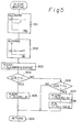
- Figure 4 is a routine for detecting surging, which is one part of an A/D conversion routine executed at every predetermined time period.
- the output signal LNSR of the lean mixture sensor 7 is fetched from the lean mixture sensor 7 via the A/D converter 101 and is stored in the RAM 108.
- other A/D conversions such as the intake air pressure data PM and the coolant temperature data THW, are also fetched and then stored in the RAM 108.
- an absolute value S between the current output LNSR and the previously fetched output LNSR of the lean mixture sensor 7 is calculated by: S ⁇ ILNSR - LNSROI - 1 where "1" is a constant for eliminating the fluctuation of the output signal LNSR of the lean mixture sensor 7 due to the feedback control of the air-fuel ratio. Therefore, this value "1" is not always necessary.
- the value S is guarded by a minimum value, which is, in this case, 0. That is, at step 403, it is determined whether or not S ⁇ 0 is satisfied. Only if S ⁇ 0 does the control proceed to step 404, which causes the value S to be 0.
- the value S is added to its cumulative value ⁇ LN, i.e., ⁇ LN ⁇ ⁇ LN + S.
- step 406 it is determined whether or not the engine is in a steady state.
- the conditions for a steady state are as follows:
- step 410 clears a counter T.
- the counter T is an up counter incremented at every predetermined time period, such as 32 ms, and is used for measuring the duration of the steady state.
- the control proceeds to step 411, which clears the cumulative value ALN.
- step 412 the value LNSRO is replaced by the content of LNSR the next execution.
- step 406 proceeds via step 407 to steps 411 and 412.
- step 407 the measuring operation of the steady state duration continues.
- step 407 proceeds via step 408 to step 412.
- step 408 the control at step 407 proceeds via step 408 to step 412.
- step 408 After 1.5 s after entering the steady state, the control at step 408 proceeds to step 409, which calculates
- ⁇ LN is a blunt value (mean value) of ⁇ LN, and n is, for example, 16. Then, the control proceeds via steps 410, 411, and 412 to step 413.
- step 406 proceeds to step 410, thus returning to an initial state.
- the output signal LNSR of the lean mixture sensor 7 represents the change of the combustion state of the engine and, accordingly, the cumulative value ⁇ LN represents a surging level. That is, when the change of the combustion state of the engine is small, as illustrated in Fig. 3A, the cumulative value ⁇ LN increases slowly as indicated by a solid-dotted line ⁇ LN A in Fig. 3C. Contrary to this, when the change of the combustion state of the engine is large, as illustrated in Fig. 3B, the cumulative value ⁇ LN increases rapidly as indicated by a solid line ⁇ LN B in Fig. 3C. Thus, the degree of surging can be determined by ⁇ LN. In addition, the past surging levels can be reflected in the current surging level by using the blunt value ⁇ LN.
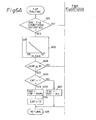
- Figure 5 is a routine for calculating a lean air-fuel ratio correction coefficient KLEAN executed at every predetermined time period. Note that the coefficient KLEAN satisfies the condition: KLEAN ⁇ 1.0.
- KLEANPM is calculated from a one-dimensional map stored in the ROM 107 by using the parameter PM as shown in the block of step 501.
- KLEANNE is calculated from a one-dimensional map stored in the ROM 107 by using the parameter Ne as shown on the block of step 502. Then at step 703, KLEAN ⁇ KLEANPM ⁇ KLEANNE.
- step 504 it is determined whether or not the blunt value ⁇ LN satisfies ⁇ LN ⁇ C 1 , and at step 506, it is determined whether or not the blunt value ⁇ LN satisfies ⁇ LN > C 2 .
- C 1 and C 2 are surging determination levels. That is, the surging determination results have hysteresis characteristics.
- step 505 decreases KLEAN by K 1 (definite value). If ⁇ LN > C 2 , the control proceeds to step 507, which increases KLEAN by K 2 (definite value). That is, if no surging is detected, KLEAN is decreases to decrease the fuel injection amount, while if surging is detected, KLEAN is increased to increase the fuel injection amount.
- step 508 causes the blunt value ⁇ LN to be (C 1 + C 2 )/2, which is an initial value, thereby avoiding an overrich air-fuel ratio.
- this step 508 is also not always necessary.
- step 509 KLEAN is not changed.
- Figure 6 is a routine for calculating an air-fuel ratio feedback correction coefficient FAF executed at every predetermined time period.
- step 601 it is determined whether or not all the feedback control (closed-loop control) conditions are satisfied.
- the feedback control conditions are as follows:
- a comparison reference value IR is calculated from a one-dimensional map stored in the ROM 107 by using the parameter KLEAN obtained by the routine of Fig. 5. Note that this one-dimensional map is shown in the block of step 602. That is, the comparison reference value IR is variable in accordance with the coefficient KLEAN, thereby changing the aimed air-fuel ratio of the feedback control in accordance with the coefficient KLEAN.
- step 603 the output LNSR Of the lean mixture sensor 7 stored in the RAM 108 is compared with the comparison reference value IR, thereby determining whether the current air-fuel ratio is on the rich side or on the lean side with respect to the aimed air-fuel ratio. If LNSR ⁇ IR so that the current air-fuel ratio is on the rich side, the control proceeds to step 604 which determines whether or not a skip flag CAF is "1".
- the value "1" of the skip flag CAF is used for a skip operation when a first change from the rich side to the lean side occurs in the controlled air-fuel ratio, while the value "0" is used for a skip operation when a first change from the lean side to the rich side occurs in the controlled air-fuel ratio.
- step 605 decreases the coefficient FAF by a relatively large amount SKP 1 .
- step 606 the skip flag CAF is cleared, i.e. CAF ⁇ "0".
- step 607 decreases the coefficient FAF by a relatively small amount K 1 .
- SKP1 is a constant for a skip operation which remarkably increases the coefficient FAF when a first change from the lean side (LNSR > IR) to the rich side (LNSR ⁇ IR) occurs in the controlled air-fuel ratio
- KI 1 is a constant for an integration operation which gradually decreases the coefficient FAF when the controlled air-fuel ratio is on the rich side.
- step 603 if LNSR > IR so that the current air-fuel ratio is on the lean side, the control proceeds to step 608, which determines whether or not the skip flag CAF is "0". As a result, if the skip flag CAF is "0", the control proceeds to step 609, which increases the coefficient FAF by a relatively large amount SKP2. Then, at step 610, the skip flag CAF is set, i.e., CAF ⁇ "1". Thus, when the control at step 608 is further carried out, the control proceeds to step 611, which increases the coefficient FAF by a relatively small amount KI 2 .
- SKP 2 is a constant for a skip operation which remarkably increases the coefficient FAF when a first change from the rich side (LNSR ⁇ IR) to the lean side (LNSR > IR) occurs in the controlled air-fuel ratio
- KI 2 is a constant for an integration operation which gradually increases the coefficient FAF when the controlled air-fuel ratio is on the lean side.
- the air-fuel ratio feedback correction coefficient FAF obtained at step 605, 607, 609, 611, or 612 is stored in the RAM 108, and the routine of Fig. 6 is completed by step 613.
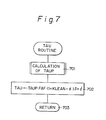
- Figure 7 is a routine for calculating a fuel injection time period TAU executed at every predetermined crank angle.
- this routine is executed at every 360°CA in a simultaneous fuel injection system for simultaneously injecting all the injectors and is executed at every 180°CA in a sequential fuel injection system applied to a four-cylinder engine for sequentially injecting the injectors thereof.
- a fuel injection time period TAUP is calculated from a two-dimensional map stored in the ROM 107 by using the parameters PM and Ne. Then, at step 702, a fuel injection time period TAU is calculated by TAU + TAUP ⁇ FAF ⁇ (1+KLEAN+ ⁇ ) ⁇ + ⁇ where a, 8, and y are correction factors determined by other parameters such as the signal of the intake air temperature sensor, the voltage of the battery (both not shown), and the like. Then the calculated fuel injection time period TAU is stored in the RAM 108, and the routine of Fig. 7 is completed by step 703.
- Figure 8 is a routine for controlling the fuel injection in accordance with the fuel injection time period TAU calculated by the routine of Fig. 7, executed at every predetermined crank angle. Also, this routine is executed at every 360°CA in a simultaneous fuel injection system and is executed at every 180°CA in an sequential fuel injection system applied to a four-cylinder engine.
- the fuel injection time period TAU stored in the RAM 108 is read out and is transmitted to the D register (not shown) included in the CPU 105.
- an invalid fuel injection time period TAUV which is also stored in the RAM 108 is added to the content of the D register.
- the current time CNT of the free-run counter of the timer counter 106 is read out and is added to the content of the D register, thereby obtaining an injection end time t in the D register. Therefore, at step 804, the content of the D register is stored as the injection end time t in the RAM 108.
- step 805 the current time CNT of the free-run counter is read out and is set in the D register. Then, at step 806, a small time period t 0 , which is definite or determined by the predetermined parameters, is added to the content of the D register. At step 807, the content of the D register is set in the first compare register of the timer counter 106, and at step 808, a fuel injection execution flag and a compare I interrupt permission flag are set in the registers of the timer counter 106. The routine of Fig. 8 is completed by step 809.
- step 901 the injection end time t e stored in the RAM 108 is read out and is transmitted to the D register.
- the content of the D register is set in the first compare register of the timer counter 106 and at step 903, the fuel injection execution flag and the compare I interrupt permission flag are reset.
- the routine of Fig. 9 is completed by step 904.
- the lean air-fuel ratio correction coefficient KLEAN is controlled in accordance with the surging level, i.e., aLN, and accordingly, the fuel injection time period TAU is controlled in accordance with the surging level ALN.
- FIG. 10 A second embodiment of the present invention will be explained with reference to Figs. 10 through 14. Note that this second embodiment also includes the routines of Figs. 4, 6, 7, and 9.
- the routine of Fig. 10 is provided instead of Fig. 5 of the first embodiment. That is, the steps 504 through 508 of Fig. 5 are deleted. Therefore, in the second embodiment, the lean air-fuel ratio correction coefficient KLEAN does not change in response to the surging level, i.e., ALN.
- the routine of Fig. 11 is provided instead of Fig. 8 of the first embodiment, thereby controlling the fuel injection timing in accordance with the surging level, i.e, ALN.
- an injection start time t i is calculated from a two-dimensional map stored on the ROM 107 by using the parameters PM and Ne. However, note that t i can be a definite time.
- an injection end time t e is calculated by: t e ⁇ t i + TAU + TAUV
- TAU is the fuel injection time period calculated by the routine of Fig. 7, and TAU is an invalid fuel injection time period.
- step 1103 it is determined whether or not the blunt value ⁇ LN satisfies ⁇ LN ⁇ C 1 , and at step 1104, it is determined whether or not the blunt value ALN satisfies ⁇ LN > C2 (> C1).
- step 1104 advances the injection start time t i by K 3 (definite value), and further proceeds to step 1105, which advances the injection end time t e by K 3 .
- step 1107 delays the injection start time t i by K 4 , (definite value), and further proceeds to step 1108, which delays the injection end time t e by K 4 . That is, if no surging is detected, the fuel injection timing is advanced, while if surging is detected, the fuel injection timing is delayed.
- step 1108 proceeds to step 1109, which causes the blunt value ⁇ LN to be (C1 + C 2 )/2, which is an initial value, thereby avoiding an overrich air-fuel ratio.
- this step 1109 is not always necessary.
- step 1110 If C 1 ⁇ ⁇ LN ⁇ C 2 , the control proceeds directly to step 1110. That is, the fuel injection timing is not changed.
- the current time CNT of the free-run counter is read out and is set in the D register. Then, at step 1111, the injection end time t e is added to the content of the D register. At step 1112, the content of the D register is stored as the final injection end time t in the RAM 108.
- step 1113 the current time CNT of the free-run counter is read out and is set in the D register. Then, at step 1114, the injection start time tiis added to the content of the D register. At step 1115, the content of the D register is set in the first compare register of the timer counter 106, and at step 1116, the fuel injection execution flag and the compare I interrupt permission flag are set in the registers of the timer counter 106. The routine of Fig. 11 is completed by step 1117.
- the driven circuit 104 of the control circuit 10 generates in injection pulse as shown in Fig. 12, in which DC and TDC designate a bottom dead center and a top dead center, respectively, of one cylinder.
- the output signal LNSR of the lean sensor 7 is accumulated for 1 s at every 1.5 s, as illustrated in FIg. 13A, and the blunt value ALN is calculated at every 1.5 s as illustrated in Fig. 13B. If the blunt value ⁇ LN exceeds the value C 2 , the fuel injection timing is delayed from P 1 to P 2 , as illustrated in Fig. 13C, while if the blunt value LN becomes smaller than the value C 1 , the fuel injection timing is advanced from P 2 to P 3 (or from P 3 to P 4 ), as illustrated in Fig. 13C.
- the values C 1 and C 2 are determined suitably for the surging level ⁇ LN and the NOx emission.
- feedback of the fuel injection timing is controlled so that the degree of surging is brought close to (C l + C 2 )/2.
- the delay amount K 4 is considerably larger than the advance amount K 3 .
- the surging level ⁇ LN is changed as indicated by ⁇ LN 1 in Fig. 15, when it exceeds the value C 1 , while it is changed as indicated by ⁇ LN 2 in Fig. 15, when it becomes smaller than the value C 2 .
- Figure 16 is a modification of the routine of Fig. 11.
- steps 1601 through 1606 are provided instead of steps 1103 through 1109 of Fig. 11. That is, at step 1601, the difference A between the blunt value LN and a definite value C A is calculated, i.e., A ⁇ ⁇ LN - C A .
- the definite value C A is, for example, equal to (C 1 + C 2 )/2 (see step 1109 of Fig. 11). Then, at step 1602, it is determined whether or not
- the injection start time t i is changed by adding K 0 thereto.
- the injection end time t e is changed by adding K 0 thereto. In this case, if K 0 is positive, the fuel injection timing is delayed, while if K 0 is negative, the fuel injection time is advanced.
- correction amount K 0 can be also changed by the engine speed N , the coolant temperature THW, the intake air pressure PM, and the like, in addition to the value
- a third embodiment of the present invention will be explained with reference to Figs. 18 and 19. Note that this third embodiment also includes the routine of Fig. 4.
- Figure 18 is a routine for controlling an ignition timing executed at every predetermined crank angle, such as 180°CA, in a four-cylinder engine.
- a base advance angle ⁇ B (°CA) is calculated from a two-dimensional map stored on the ROM 107 using the parameters PM and N .
- step 1802 it is determined whether or not the blunt value ⁇ LN satisfies ⁇ LN ⁇ C 1 , and at step 1804, it is determined whether or not the blunt value ⁇ LN satisfies ⁇ LN > C 2 .
- step 1803 decreases ⁇ B by K 5 (definite value), while if ⁇ LN > C 2 , the control proceeds to step 1805, which increases 6 B by K 6 (definite value). That is, if no surging is detected, ⁇ B is decreased to delay the ignition timing, while if surging is detected, 6 B is increased to advance the ignition timing. That is, in this case, the engine torque is increased by advancing the ignition timing, thus reducing surging.
- step 1805 proceeds to step 1806 which causes the blunt value ALN to be (C 1 + C 2 )/2, which is an initial value, thereby avoiding the overadvance of the ignition timing.
- this step 1806 is also not always necessary.
- the base advance value ⁇ B is corrected by other parameters to obtain a final ignition timing.
- the ignition timing is converted into time (current supply start timing), and a term of 30°CA is converted into time t ' , which is then stored in the RAM 108.
- the current time CNT of the free-run counter is read out and is set in the D register.
- the current supply start timing t i is added to the content of the D register.
- the content of the D register is set in the second compare register of the timer counter 106.
- step 1810 a current supply execution flag and a compare II interrupt permission flag are set in the registers of the timer counter 106.
- the routine of Fig. 18 is completed by step 1811.
- a current supply signal due to the presence of the current supply execution flag is transmitted from the timer counter 106 via the I/O interface 103 to the igniter 16 thereby initiating current supply to the igniter 16.
- a compare II interrupt signal due to. the presence of the compare II interrupt permission flag is transmitted from the timer counter 106 to the CPU 105, thereby initiating a compare II interrupt routine as illustrated in Fig. 19.
- step 1901 the current supply end timing t' stored in the RAM 108 is read out and is transmitted to the D register.
- the content of the D register is set in the second compare register of the timer counter 106, and at step 1903, the current supply execution flag and the compare II interrupt permission flag are reset.
- the routine of Fig. 19 is completed by step 1904.
- the igniter 16 is turned on before 30° CA of the ignition timing, and the igniter 16 is turned otf at the ignition timing.
- an ignition signal as shown in Fig. 20 is generated.
- A6 of Fig. 20 represents the correction amount by steps 1803, 1805, and 1807.
- feedback of the ignition timing is controlled so that the surging level is brought close to (C1 + C 2 )/2.
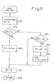
- FIG. 21 A fourth embodiment of the present invention will be explained with reference to Fig. 21. Note that this fourth embodiment also includes the routine of Fig. 4.
- Figure 21 is a routine for controlling the opening of the EGR value 17 executed at every predetermined time period.
- a duty ratio DT is calculated from a two-dimensional map stored on the ROM 107 using the parameters PM and N .
- step 2102 it is determined whether or not the blunt value ⁇ LN satisfies ⁇ LN ⁇ C 1 , and at step 2104, it is determined whether or not the blunt value ⁇ LN satisfies ⁇ LN > C 2 .
- step 2103 which increases DT by K 7 (definite value)
- step 2105 which decreases DT by K 8 (definite value). That is, if no surging is detected, DT is increased to increase the EGR amount, while if surging is detected, DT is decreased to decrease the EGR amount.
- step 2105 the control at step 2105 proceeds to step 2106, which causes the blunt value ⁇ LN to be (C 1 + C 2 )/2, which is an initial value, thereby avoiding overage of the EGR amount.
- this step 2106 is not always necessary.
- step 2107 If C 1 ⁇ ⁇ LN ⁇ C 2 , the control proceeds directly to step 2107. That is, DT is not changed.
- the calculated duty ratio DT is set in the driver circuit 110, and accordingly, a driving signal having the duty-ratio DT is applied by the driver circuit 110 to the solenoid 19, thus controlling the EGR value 17.
- the opening of the EGR valve 17 has a relationship to the duty ratio DT of the driving signal as shown in Fig. 22.
- the routine of Fig. 21 is completed by step 2108.
- the EGR amount when the surging level, i.e., ⁇ LN is large, the EGR amount is decreased, while when the surging level is small, the EGR amount is increased. That is, feedback of the EGR amount is controlled so that the surging level is brought close to (C 1 + C 2 )/ 2,
- the present invention can be also applied to a system in which the EGR valve 17 is controlled by a step motor or the like, instead of the duty ratio control.
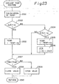
- a fifth embodiment of the present invention will be explained with reference to Fig. 23. Note that this fifth embodiment also includes the routine of Fig. 4.
- Figure 23 is a routine for controlling the coolant temperature THW executed at every predetermined time period.
- an aimed coolant duty ratio temperature TEMP is calculated from a two-dimensional map stored on the ROM 107 using the parameters PM and N .
- step 2302 it is determined whether or not the blunt value ALN satisfies ⁇ LN ⁇ C 1 , and at step 2304, it is determined whether or not the blunt value ⁇ LN satisfies ⁇ LN > C 2 .
- step 2303 which increases TEMP by K 9 (definite value)
- step 2305 which decreases TEMP by K 10 (definite value). That is, if no surging is detected, TEMP is decreased to decrease the coolant temperature THW, while if surging is detected, TEMP is decreased to increase coolant temperature THW.
- step 2305 proceeds to step 2306, which causes the blunt value ⁇ LN to be (C 1 + C 2 )/2, which is an initial value, thereby avoiding overheating of the coolant.
- this step 2306 is not always necessary.
- step 2307 If C 1 ⁇ ⁇ LN ⁇ C 2 , the control proceeds directly to step 2307. That is, TEMP is not changed.
- step 2307 it is determined whether or not the current coolant temperature THW is larger than the aimed temperature TEMP. It THW > TEMP, at step 2308, the (PL) 105 closes the control valve 25, while if THW ⁇ TEMP, the CPU 105 opens the control valve 25. That is, the control valve 25 is driven so that the coolant temperature THW is brought close to the aimed temperature TEMP. Then, this routine of Fig. 23 is completed by step 2310.
- the coolant temperature T HW is increased, while when the surging level is small, the coolant temperature THW is decreased. That is, feedback of the coolant temperature THW controlled so that the surging level is brought close to (C l + C 2 )/2.
- the present invention can be also applied to a fuel injection system using the other parameters such as the intake air amount and the engine speed or the throttle opening value and the engine speed.
- surging or misfiring can be detected without using a gravity sensor, thus reducing manufacturing costs.
Landscapes
- Engineering & Computer Science (AREA)
- Chemical & Material Sciences (AREA)
- Combustion & Propulsion (AREA)
- Mechanical Engineering (AREA)
- General Engineering & Computer Science (AREA)
- Electrical Control Of Air Or Fuel Supplied To Internal-Combustion Engine (AREA)
Abstract
Description
- The present invention relates to a method and apparatus for detecting surging in an internal combustion engine.
- As measures taken against exhaust gas pollution and fuel consumption, a lean burn system has recently been developed. According to this lean burn system, a lean mixture sensor is provided for generating an analog current proportional to the lean air-fuel mixture in an exhaust pipe of an engine. Feedback control of the air-fuel ratio of the engine is possible using the analog output of the lean mixture sensor, thereby attaining an arbitrary air-fuel ratio on the lean side.
- In such a lean burn system, the controlled air-fuel ratio is brought close to a misfiring limit to reduce the NOx emission. If the characteristics of the lean mixture sensor fluctuate, the engine may suffer from surging or misfiring, thus reducing drivability.
- In the prior art, the detection of surging or misfiring is carried out by using a gravity sensor. Such a sensor, however, is disadvantageous in cost.
- It is an object of the present invention to provide a method and apparatus for detecting surging in an internal combustion engine without using a gravity sensor.
- Another object of the present invention is to suppress surging in the engine.
- Still another object of the present invention is to reduce the NOx emission in the exhaust gas without inviting surging.
- According to the present invention, the concentration of a specific composition is detected, and the fluctuation thereof is calculated. Surging in the engine is detected by comparing the calculated fluctuation with a predetermined value.
- In addition, when surging is detected, a parameter of the engine such as the fuel supply (injection) amount, fuel supply (injection) timing, exhaust gas recirculation (EGR) amount, or the coolant temperature of the engine, is controlled so as to suppress surging.
- When no surging is detected, the above-mentioned parameter of the engine is controlled to a level close to surging, thus reducing the NOx emission. That is, in this case, feedback of the air-fuel ratio is carried out to bring the ratio close to an optimum air-fuel ratio for both suppressing surging and reducing the NOx emission.
- The present invention will be more clearly understood from the description as set forth below with reference to the accompanying drawings, wherein:
- Fig. 1 is a schematic diagram of an internal combustion engine according to the present invention;
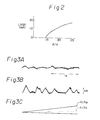
- Fig. 2 is a graph showing the output characteristics of the lean mixture sensor of Fig. 1;
- Figs. 3A and 3B are timing diagrams showing the output of the lean mixture sensor of Fig. 1;
- Fig. 3C is a timing diagram showing the accumulated fluctuation of the output of the lean mixture sensor of Fig. 1;
- Figs. 4 through 11, 16, 18, 19, 21, and 23 are flow charts showing the operation of the control circuit of Fig. 1;
- Figs. 12 through 15 are graphs for explaining the routine of Fig. 11;
- Fig. 17 is a graph for explaining the routine of Fig. 16;
- Fig. 20 is a graph for explaining the routines of Figs. 18 and 19; and
- Fig. 22 is a graph for explaining the routine of Fig. 21.
- In Fig. 1, which illustrates an internal combustion engine according to the present invention,
reference numeral 1 designates a four-cycle spark ignition engine disposed in an automotive vehicle.. Provided in an air-intake passage 2 of theengine 1 is asurge tank 3 in which apressure sensor 4 is provided. Thepressure sensor 4 is used for detecting the absolute pressure within the intake-air passage 2 and transmits its output signal to a multiplexer-incorporating analog-to-digital (A/D)converter 101 of acontrol circuit 10. - Additionally provided in the air-
intake passage 2 is afuel injector 5 for supplying pressurized fuel from the fuel system (not shown) to the air-intake port of the cylinder of theengine 1. In this case, other fuel injectors are also provided for other cylinders, though not shown in Fig. 1. - Provided in an exhaust gas passage 6 of the
engine 1 is alean mixture sensor 7 for detecting the concentration of oxygen composition in the exhaust gas. - The
lean mixture sensor 7 generates a limit current signal LNSR as shown in Fig. 2 and transmits it via a current-to-voltage converter circuit 102 of thecontrol circuit 10 to the A/D converter 101 thereof. - Disposed in a
water jacket 8 of a cylinder block of theengine 1 is a coolant sensor 9 for detecting the coolant temperature THW. The coolant sensor 9 generates an analog voltage signal in response to the coolant temperature THW and transmits it to the A/D converter 101. - Disposed in a distributor 11 are crank angle sensors 12 and 13 for detecting the angle of the crankshaft (not shown) of the
engine 1. In this case, the crank-angle sensor 12 generates a pulse signal at every 720° crank angle (CA) while the crank-angle sensor 13 generates a pulse signal at every 30°CA. In this case, the pulse signals of the crank angle sensors 12 and 13 are supplied to an input/output (I/O)interface 103 of thecontrol circuit 10. The output of the crank angle sensor 13 is then supplied to interruption terminals of a central processing unit (CPU) 105. - Provided for each cylinder is a
spark plug 14 connected via the distributor 11 to anignition coil 15 which is driven by anigniter 16. Theigniter 16 is connected to the I/O interface 103 of thecontrol circuit 10. That is, current is supplied to theigniter 16 at a current supply start timing such as at 30°CA before a current supply end timing, thus turning on theigniter 16. Then, at a current supply end timing, i.e., at an ignition timing, theigniter 16 is turned off. This ignition of one cylinder of the engine is performed. - Linked between the exhaust gas passage 6 and the
intake air passage 2 is anEGR passage 17 having anEGR valve 18 therein. TheEGR valve 18 is linked to a negative pressure actuator 19 which is selectively connected by asolenoid 20 to a negative pressure port of thesurge tank 3 or to anatmosphere filter 21. When thesolenoid 20 is energized by thecontrol circuit 10, the negative pressure of thesurge tank 3 is introduced via thesolenoid 20 into the actuator 19 to open theEGR valve 18. Contrary to this, when thesolenoid 20 is not energized, the atmospheric air is introduced via thefilter 21 and thesolenoid 20 into the actuator 19 to close theEGR valve 18. In this case, thesolenoid 20 is controlled by the duty ratio of a driven signal generated from adriver circuit 110 of thecontrol circuit 10. -
Reference numeral 22 designates a radiator having a bottom tank linked via awater pipe 23 to a water jacket 8' of theengine 1 and an upper tank linked via awater pipe 24 to the water pump (not shown). Disposed in thewater pipe 24 is a coolanttemperature control valve 25 for adjusting the coolant temperature. - The
control circuit 10, which may be constructed by a microcomputer, includes a driver circuit 104 for driving thefuel injector 5, atimer counter 106, a read-only memory (ROM) 107 for storing a main routine, interrupt routines such as a fuel injection routine, an ignition timing routine, tables (maps), constants, etc., a random-access memory 108 (RAM) for storing temporary data, aclock generator 109 for generating various clock signals, and the like, in addition to the A/D converter 101, the current-to-voltage converter circuit 102, the I/O interface 103, theCPU 105, and the drivencircuit 110. - The
timer counter 106 may include a free-run counter, a first compare register, a first comparator for comparing the content of the free-run counter with that of the first compare register, flag registers for a first compare interruption, injection control, and the like, thus controlling the injection start and end operation. Further, thetimer counter 106 may include a second compare register, a second comparator for comparing the content of the free-run counter with that of the second compare register, flag registers for a second compare interruption ignition control, and the like, thus controlling the current supply start and end operation for ignition. - Interruptions occur at the
CPU 105, when the A/D converter 101 completes an A/D conversion and generates an interrupt signal; when one of the crank angle sensors 13 generates a pulse signal; when thetimer counter 106 generates a compare interrupt signal; and when theclock generator 109 generates a special clock signal. - The pressure data PM of the
pressure sensor 4 and the limit current data LNSR of thelean mixture sensor 7 are fetched by an A/D conversion routine executed at every predetermined time period and are then stored in theRAM 108. That is, the data PM and LNSR in the RAM 108 are renewed at every predetermined time period. The engine speed Ne is calculated by an interrupt routine executed at 30°CA, i.e., at every pulse signal of the crank angle sensor 13, and is then stored in theRAM 108. - The principle for detecting surging according to the present invention will be explained with reference to Figs. 3A and 3B. When driving in a steady state wherein the controlled air-fuel ratio is relatively on the rich side with respect to a misfiring limit, the output signal LNSR of the
lean mixture sensor 7 is almost unchanged, as shown in Fig. 3A. Contrary to this, when driving in a steady state wherein the controlled air-fuel ratio is close to the misfiring limit, protrusions on the lean side are often generated in the output signal LNSR of thelean mixture sensor 7, as shown in Fig. 3B. That is, the fluctuations of the output signal in Fig. 3B are larger than in Fig. 3A. The present invention discriminates the waveform as shown in Fig. 3B from the waveform as shown in Fig. 3A, thereby detecting surging. In addition, at least one engine parameter, such as the fuel amount, the fuel supply timing, the ignition timing, the EGR amount, or the coolant temperature, is controlled in accordance with the detection of surging. - The operation of the control circuit of Fig. 1 will be explained with reference to Figs. 4 through 11, 16, 18, 19, 21, and 23.
- Figure 4 is a routine for detecting surging, which is one part of an A/D conversion routine executed at every predetermined time period.
- At
step 401, the output signal LNSR of thelean mixture sensor 7 is fetched from thelean mixture sensor 7 via the A/D converter 101 and is stored in theRAM 108. In this routine, note that other A/D conversions, such as the intake air pressure data PM and the coolant temperature data THW, are also fetched and then stored in theRAM 108. - At
step 402, an absolute value S between the current output LNSR and the previously fetched output LNSR of thelean mixture sensor 7 is calculated by:
S ← ILNSR - LNSROI - 1
where "1" is a constant for eliminating the fluctuation of the output signal LNSR of thelean mixture sensor 7 due to the feedback control of the air-fuel ratio. Therefore, this value "1" is not always necessary. Atsteps step 403, it is determined whether or not S < 0 is satisfied. Only if S < 0 does the control proceed to step 404, which causes the value S to be 0. - At step 405, the value S is added to its cumulative value ΔLN, i.e.,
ΔLN ← ΔLN + S. - At
step 406, it is determined whether or not the engine is in a steady state. For example, the conditions for a steady state are as follows: - (1) the current air-fuel ratio is larger than a predetermined value;
- (2) the engine speed N is within a predetermined range;
- (3) the intake air pressure PM is within a predetermined range; and
- (4) the change of the intake air pressure PM is smaller than a predetermined value.
- Of course, other conditions may be required.
- If not in a steady state, the control proceeds to step 410, which clears a counter T. Note that the counter T is an up counter incremented at every predetermined time period, such as 32 ms, and is used for measuring the duration of the steady state. Then, the control proceeds to step 411, which clears the cumulative value ALN. Then, at
step 412, the value LNSRO is replaced by the content of LNSR the next execution. - Within 0.5 s after entering the steady state, the control at
step 406 proceeds viastep 407 tosteps - Next, after 0.5 s after entering the steady state, the control at
step 407 proceeds viastep 408 to step 412. Thus, since the cumulative value ΔLN is not cleared, the accumulation of the value S calculated atstep 402 starts. - After 1.5 s after entering the steady state, the control at
step 408 proceeds to step 409, which calculates -

steps - Note that, when the engine returns to a non-steady state before 1.5 s after entering the steady state, the control at
step 406 proceeds to step 410, thus returning to an initial state. - As explained above, the output signal LNSR of the
lean mixture sensor 7 represents the change of the combustion state of the engine and, accordingly, the cumulative value ΔLN represents a surging level. That is, when the change of the combustion state of the engine is small, as illustrated in Fig. 3A, the cumulative value ΔLN increases slowly as indicated by a solid-dotted line ΔLNA in Fig. 3C. Contrary to this, when the change of the combustion state of the engine is large, as illustrated in Fig. 3B, the cumulative value ΔLN increases rapidly as indicated by a solid line ΔLNB in Fig. 3C. Thus, the degree of surging can be determined by ΔLN. In addition, the past surging levels can be reflected in the current surging level by using the blunt value ΔLN. - Figure 5 is a routine for calculating a lean air-fuel ratio correction coefficient KLEAN executed at every predetermined time period. Note that the coefficient KLEAN satisfies the condition:
KLEAN ≤ 1.0. - At
step 501, KLEANPM is calculated from a one-dimensional map stored in theROM 107 by using the parameter PM as shown in the block ofstep 501. Also, atstep 502, KLEANNE is calculated from a one-dimensional map stored in theROM 107 by using the parameter Ne as shown on the block ofstep 502. Then atstep 703,
KLEAN ← KLEANPM·KLEANNE. - At
step 504, it is determined whether or not the blunt valueΔLN satisfiesΔLN < C1, and atstep 506, it is determined whether or not the blunt valueΔLN satisfiesΔLN > C2. Note that C1 and C2(Cl < C2) are surging determination levels. That is, the surging determination results have hysteresis characteristics. - If
ΔLN < Cl , then the control proceeds to step 505, which decreases KLEAN by K1 (definite value). IfΔLN > C2 , the control proceeds to step 507, which increases KLEAN by K2 (definite value). That is, if no surging is detected, KLEAN is decreases to decrease the fuel injection amount, while if surging is detected, KLEAN is increased to increase the fuel injection amount. - Then, the control at
step 507 proceeds to step 508, which causes the blunt value ΔLN to be (C1 + C2)/2, which is an initial value, thereby avoiding an overrich air-fuel ratio. However, thisstep 508 is also not always necessary. - If C1 ≦
ΔLN ≦ C2 , the control proceeds directly to step 509. That is, KLEAN is not changed. - According to the routine 5, feedback of the air-fuel ratio, i.e., the fuel injection amount, is controlled so that the surging level is brought close to (C1 + C2)/2.
- Figure 6 is a routine for calculating an air-fuel ratio feedback correction coefficient FAF executed at every predetermined time period.
- At
step 601, it is determined whether or not all the feedback control (closed-loop control) conditions are satisfied. The feedback control conditions are as follows: - i) the engine is not in a starting state;
- ii) the coolant temperature THW is higher than a definite value; and
- iii) the power fuel increment FPOWER is 0.
- Of course, other feedback control conditions are introduced as occasion demands. However, an explanation of such other feedback control conditions is omitted.
- If one or more of the feedback control conditions is not satisfied, the control proceeds to step 612, in which the coefficient FAF is caused to be 1.0 (FAF = 1.0), thereby carrying out an open-loop control operation. Contrary to this, if all the feedback control conditions are satisfied, the control proceeds to step 602.
- At
step 602, a comparison reference value IR is calculated from a one-dimensional map stored in theROM 107 by using the parameter KLEAN obtained by the routine of Fig. 5. Note that this one-dimensional map is shown in the block ofstep 602. That is, the comparison reference value IR is variable in accordance with the coefficient KLEAN, thereby changing the aimed air-fuel ratio of the feedback control in accordance with the coefficient KLEAN. - At
step 603, the output LNSR Of thelean mixture sensor 7 stored in theRAM 108 is compared with the comparison reference value IR, thereby determining whether the current air-fuel ratio is on the rich side or on the lean side with respect to the aimed air-fuel ratio. If LNSR < IR so that the current air-fuel ratio is on the rich side, the control proceeds to step 604 which determines whether or not a skip flag CAF is "1". - Note that the value "1" of the skip flag CAF is used for a skip operation when a first change from the rich side to the lean side occurs in the controlled air-fuel ratio, while the value "0" is used for a skip operation when a first change from the lean side to the rich side occurs in the controlled air-fuel ratio.
- As a result, if the skip flag CAF is "1", the control proceeds to step 605, which decreases the coefficient FAF by a relatively large amount SKP1. Then, at
step 606, the skip flag CAF is cleared, i.e. CAF ← "0". Thus, when the control atstep 604 is further carried out, the control proceeds to step 607, which decreases the coefficient FAF by a relatively small amount K1. Here, SKP1 is a constant for a skip operation which remarkably increases the coefficient FAF when a first change from the lean side (LNSR > IR) to the rich side (LNSR < IR) occurs in the controlled air-fuel ratio, while KI1 is a constant for an integration operation which gradually decreases the coefficient FAF when the controlled air-fuel ratio is on the rich side. - On the other hand, at
step 603, if LNSR > IR so that the current air-fuel ratio is on the lean side, the control proceeds to step 608, which determines whether or not the skip flag CAF is "0". As a result, if the skip flag CAF is "0", the control proceeds to step 609, which increases the coefficient FAF by a relatively large amount SKP2. Then, atstep 610, the skip flag CAF is set, i.e., CAF ← "1". Thus, when the control atstep 608 is further carried out, the control proceeds to step 611, which increases the coefficient FAF by a relatively small amount KI2. Here, SKP2 is a constant for a skip operation which remarkably increases the coefficient FAF when a first change from the rich side (LNSR < IR) to the lean side (LNSR > IR) occurs in the controlled air-fuel ratio, while KI2 is a constant for an integration operation which gradually increases the coefficient FAF when the controlled air-fuel ratio is on the lean side. - The air-fuel ratio feedback correction coefficient FAF obtained at
step RAM 108, and the routine of Fig. 6 is completed bystep 613. - Figure 7 is a routine for calculating a fuel injection time period TAU executed at every predetermined crank angle. For example, this routine is executed at every 360°CA in a simultaneous fuel injection system for simultaneously injecting all the injectors and is executed at every 180°CA in a sequential fuel injection system applied to a four-cylinder engine for sequentially injecting the injectors thereof.
- At
step 701, a fuel injection time period TAUP is calculated from a two-dimensional map stored in theROM 107 by using the parameters PM and Ne. Then, at step 702, a fuel injection time period TAU is calculated by TAU + TAUP·FAF·(1+KLEAN+α)·β+γ
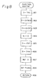
where a, 8, and y are correction factors determined by other parameters such as the signal of the intake air temperature sensor, the voltage of the battery (both not shown), and the like. Then the calculated fuel injection time period TAU is stored in theRAM 108, and the routine of Fig. 7 is completed bystep 703. - Figure 8 is a routine for controlling the fuel injection in accordance with the fuel injection time period TAU calculated by the routine of Fig. 7, executed at every predetermined crank angle. Also, this routine is executed at every 360°CA in a simultaneous fuel injection system and is executed at every 180°CA in an sequential fuel injection system applied to a four-cylinder engine.
- At
step 801, the fuel injection time period TAU stored in theRAM 108 is read out and is transmitted to the D register (not shown) included in theCPU 105. Atstep 802, an invalid fuel injection time period TAUV which is also stored in theRAM 108 is added to the content of the D register. In addition, atstep 803, the current time CNT of the free-run counter of thetimer counter 106 is read out and is added to the content of the D register, thereby obtaining an injection end time t in the D register. Therefore, atstep 804, the content of the D register is stored as the injection end time t in theRAM 108. - Again at
step 805, the current time CNT of the free-run counter is read out and is set in the D register. Then, atstep 806, a small time period t0, which is definite or determined by the predetermined parameters, is added to the content of the D register. Atstep 807, the content of the D register is set in the first compare register of thetimer counter 106, and atstep 808, a fuel injection execution flag and a compare I interrupt permission flag are set in the registers of thetimer counter 106. The routine of Fig. 8 is completed bystep 809. - Thus, when the current time CNT of the free-run counter reaches the first compare register, an injection-on signal due to the presence of the fuel injection execution flag is transmitted from the
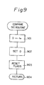
timer counter 106 via the I/O interface 103 to the driver circuit 104, thereby initiating fuel injection by thefuel injector 7. Simultaneously, a compare I interrupt signal due to the presence of the compare I interrupt permission flag is transmitted from thetimer counter 106 to theCPU 105, thereby initiating a compare I interrupt routine as illustrated in Fig. 9. - The completion of the fuel injection will be explained with reference to Fig. 9. At
step 901, the injection end time te stored in theRAM 108 is read out and is transmitted to the D register. Atstep 902, the content of the D register is set in the first compare register of thetimer counter 106 and atstep 903, the fuel injection execution flag and the compare I interrupt permission flag are reset. The routine of Fig. 9 is completed bystep 904. - Thus, when the current time CNT of the free-run counter reaches the first compare register, an injection-off signal due to the absence of the fuel injection execution flag is transmitted from the
timer counter 106 via the I/O interface 103 to the driver circuit 104, thereby ending the fuel injection by thefuel injector 5. In this case, however, no compare interrupt signal is generated due to the absence of the compare I interrupt permission flag. - Thus, fuel injection of the
fuel injector 5 is carried out for the time period TAU. - Thus, according to the routines of Figs. 4 through 9, as a first embodiment of the present invention, the lean air-fuel ratio correction coefficient KLEAN is controlled in accordance with the surging level, i.e., aLN, and accordingly, the fuel injection time period TAU is controlled in accordance with the surging level ALN.
- A second embodiment of the present invention will be explained with reference to Figs. 10 through 14. Note that this second embodiment also includes the routines of Figs. 4, 6, 7, and 9.
- The routine of Fig. 10 is provided instead of Fig. 5 of the first embodiment. That is, the
steps 504 through 508 of Fig. 5 are deleted. Therefore, in the second embodiment, the lean air-fuel ratio correction coefficient KLEAN does not change in response to the surging level, i.e., ALN. In addition, the routine of Fig. 11 is provided instead of Fig. 8 of the first embodiment, thereby controlling the fuel injection timing in accordance with the surging level, i.e, ALN. - The routine ot Fig. 11 will be explained below.
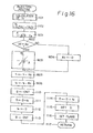
- At
step 1101, an injection start time ti is calculated from a two-dimensional map stored on theROM 107 by using the parameters PM and Ne. However, note that ti can be a definite time. Atstep 1102, an injection end time te is calculated by:
te ← ti + TAU + TAUV - where TAU is the fuel injection time period calculated by the routine of Fig. 7, and TAU is an invalid fuel injection time period.
- At
step 1103, it is determined whether or not the blunt valueΔLN satisfiesΔLN < C1 , and atstep 1104, it is determined whether or not the blunt value ALN satisfiesΔLN > C2 (> C1). - If ALN < C1 , then the control proceeds to step 1104, which advances the injection start time ti by K3 (definite value), and further proceeds to step 1105, which advances the injection end time te by K3. Contrary to this if ALN > C2 , then the control proceeds to step 1107 which delays the injection start time ti by K4 , (definite value), and further proceeds to step 1108, which delays the injection end time te by K4. That is, if no surging is detected, the fuel injection timing is advanced, while if surging is detected, the fuel injection timing is delayed.
- Then, the control at
step 1108 proceeds to step 1109, which causes the blunt valueΔLN to be (C1 + C2)/2, which is an initial value, thereby avoiding an overrich air-fuel ratio. However, this step 1109 is not always necessary. - If C1 ≦
ΔLN ≦ C2 , the control proceeds directly to step 1110. That is, the fuel injection timing is not changed. - At
step 1110, the current time CNT of the free-run counter is read out and is set in the D register. Then, at step 1111, the injection end time te is added to the content of the D register. Atstep 1112, the content of the D register is stored as the final injection end time t in theRAM 108. - e Again at
step 1113, the current time CNT of the free-run counter is read out and is set in the D register. Then, atstep 1114, the injection start time tiis added to the content of the D register. Atstep 1115, the content of the D register is set in the first compare register of thetimer counter 106, and atstep 1116, the fuel injection execution flag and the compare I interrupt permission flag are set in the registers of thetimer counter 106. The routine of Fig. 11 is completed bystep 1117. - Thus, when the current time CNT of the free-run counter reaches the first compare register, an injection-on signal due to the presence of the fuel injection execution flag is transmitted from the
timer counter 106 via the I/O interface 103 to the driver circuit 104, thereby initiating fuel injection by thefuel injector 5. Simultaneously, a compare I interrupt signal due to the presence of the compare I interrupt permission flag is transmitted for thetimer counter 106 to theCPU 105, thereby initiating the compare I interrupt routine as illustrated in Fig. 9, which is already explained above. - Thus, the driven circuit 104 of the
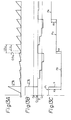
control circuit 10 generates in injection pulse as shown in Fig. 12, in which DC and TDC designate a bottom dead center and a top dead center, respectively, of one cylinder. - The effect according to the second embodiment as illustrated in Figs. 10 and 11, in addition to Figs. 4, 6, 7, and 9 will be explained with reference to Figs. 13A, 13B, 13C, and 14. The output signal LNSR of the
lean sensor 7 is accumulated for 1 s at every 1.5 s, as illustrated in FIg. 13A, and the blunt value ALN is calculated at every 1.5 s as illustrated in Fig. 13B. If the blunt value ΔLN exceeds the value C2 , the fuel injection timing is delayed from P1 to P2 , as illustrated in Fig. 13C, while if the blunt value LN becomes smaller than the value C1 , the fuel injection timing is advanced from P2 to P3 (or from P3 to P4), as illustrated in Fig. 13C. - As illustrated in Fig. 14, when the fuel injection timing (advance angle) is too delayed, the NOx emission is increased, although the surging level, i.e.,
ΔLN can be reduced. Contrary to this, when the fuel injection timing is too advanced, the surging levelΔLN is enhanced, although the NOx emission can be reduced. Therefore, the values C1 and C2 are determined suitably for the surging levelΔLN and the NOx emission. - Thus, according to the second embodiment, feedback of the fuel injection timing is controlled so that the degree of surging is brought close to (Cl + C2)/2.
- In the above-mentioned second embodiment, the delay amount K4 is considerably larger than the advance amount K3. However, these amounts K3 and K4 can be the same as each other (K3 = K4 = K). In this case, the surging level
ΔLN is changed as indicated byΔLN 1 in Fig. 15, when it exceeds the value C1 , while it is changed as indicated byΔLN 2 in Fig. 15, when it becomes smaller than the value C2. - Figure 16 is a modification of the routine of Fig. 11. In Fig. 16,
steps 1601 through 1606 are provided instead ofsteps 1103 through 1109 of Fig. 11. That is, atstep 1601, the difference A between the blunt value LN and a definite value CA is calculated, i.e.,
A ← ΔLN - CA. - The definite value CA is, for example, equal to (C1 + C2)/2 (see step 1109 of Fig. 11). Then, at
step 1602, it is determined whether or not |A| > A (definite value) is satisfied. If |A| ≦ A0 , the control proceeds to step 1604, which clears a correction amount K0 for the fuel injection timing. Contrary to this, if |A| > A0 , the control proceeds to step 1603, in which the correction amount K0 is calculated from a one-dimensional map stored in theROM 107 by using the parameter A as shown in the block ofstep 1603. - Then, at
step 1605, the injection start time ti is changed by adding K0 thereto. Also atstep 1606, the injection end time te is changed by adding K0 thereto. In this case, if K0 is positive, the fuel injection timing is delayed, while if K0 is negative, the fuel injection time is advanced. - Note that the correction amount K0 can be also changed by the engine speed N , the coolant temperature THW, the intake air pressure PM, and the like, in addition to the value |ΔLN - CA|.
- In the modified second embodiment in which the routine of Fig. 16 is used instead of that of Fig. 11, the surging level, i.e., ΔLN is changed as illustrated in Fig. 17. Therefore, feedback of the fuel injection timing is also controlled so that the surging level is brought close to CA (=(C1+C2)/2).
- A third embodiment of the present invention will be explained with reference to Figs. 18 and 19. Note that this third embodiment also includes the routine of Fig. 4.
- Figure 18 is a routine for controlling an ignition timing executed at every predetermined crank angle, such as 180°CA, in a four-cylinder engine.
- At
step 1801, a base advance angle θB (°CA) is calculated from a two-dimensional map stored on theROM 107 using the parameters PM and N . - At
step 1802, it is determined whether or not the blunt value ΔLN satisfies ΔLN < C1 , and atstep 1804, it is determined whether or not the blunt value ΔLN satisfies ΔLN > C2. - If ΔLN < C1 , then the control proceeds to step 1803, which decreases θB by K5 (definite value), while if ΔLN > C2 , the control proceeds to step 1805, which increases 6B by K6 (definite value). That is, if no surging is detected, θB is decreased to delay the ignition timing, while if surging is detected, 6 B is increased to advance the ignition timing. That is, in this case, the engine torque is increased by advancing the ignition timing, thus reducing surging.
- Then, the control at
step 1805 proceeds to step 1806 which causes the blunt value ALN to be (C1 + C2)/2, which is an initial value, thereby avoiding the overadvance of the ignition timing. However, thisstep 1806 is also not always necessary. - If C1 ≦ ΔLN ≦ C2 , the control proceeds directly to step 1807. That is, eB is not changed.
- At
step 1807, the base advance value θB is corrected by other parameters to obtain a final ignition timing. Atstep 1808, the ignition timing is converted into time (current supply start timing), and a term of 30°CA is converted into time t ' , which is then stored in theRAM 108. - At
step 1809, the current time CNT of the free-run counter is read out and is set in the D register. The current supply start timing ti is added to the content of the D register. Then, the content of the D register is set in the second compare register of thetimer counter 106. - At
step 1810, a current supply execution flag and a compare II interrupt permission flag are set in the registers of thetimer counter 106. The routine of Fig. 18 is completed bystep 1811. - Thus, when the current time CNT of the free-run counter reaches the second compare register, a current supply signal due to the presence of the current supply execution flag is transmitted from the
timer counter 106 via the I/O interface 103 to theigniter 16 thereby initiating current supply to theigniter 16. Simultaneously, a compare II interrupt signal due to. the presence of the compare II interrupt permission flag is transmitted from thetimer counter 106 to theCPU 105, thereby initiating a compare II interrupt routine as illustrated in Fig. 19. - The ignition (spark) will be explained with reference to Fig. 19. At step 1901, the current supply end timing t' stored in the
RAM 108 is read out and is transmitted to the D register. Atstep 1902, the content of the D register is set in the second compare register of thetimer counter 106, and atstep 1903, the current supply execution flag and the compare II interrupt permission flag are reset. The routine of Fig. 19 is completed bystep 1904. - Thus, when the current time CNT of the free-run counter reaches the second compare register, a current supply end signal due to the absence of the current supply execution flag is transmitted from the
timer counter 106 via the I/O interface 103 to theigniter 23 thereby generating a spark from thespark plug 14. - In this case, however, no compare interrupt signal is generated due to the absence of the compare II interrupt permission flag.
- Thus, the
igniter 16 is turned on before 30° CA of the ignition timing, and theigniter 16 is turned otf at the ignition timing. - That is, an ignition signal as shown in Fig. 20 is generated. Note that A6 of Fig. 20 represents the correction amount by
steps - According to the third embodiment, feedback of the ignition timing is controlled so that the surging level is brought close to (C1 + C2)/2.
- A fourth embodiment of the present invention will be explained with reference to Fig. 21. Note that this fourth embodiment also includes the routine of Fig. 4.
- Figure 21 is a routine for controlling the opening of the
EGR value 17 executed at every predetermined time period. - At
step 2101, a duty ratio DT is calculated from a two-dimensional map stored on theROM 107 using the parameters PM and N . - At
step 2102, it is determined whether or not the blunt valueΔLN satisfiesΔLN < C1 , and atstep 2104, it is determined whether or not the blunt value ΔLN satisfiesΔLN > C2. - If
ΔLN < C1 , then the control proceeds to step 2103, which increases DT by K7 (definite value), while ifΔLN > C2 , the control proceeds to step 2105, which decreases DT by K8 (definite value). That is, if no surging is detected, DT is increased to increase the EGR amount, while if surging is detected, DT is decreased to decrease the EGR amount. - Then, the control at
step 2105 proceeds to step 2106, which causes the blunt valueΔLN to be (C1 + C2)/2, which is an initial value, thereby avoiding overage of the EGR amount. However, thisstep 2106 is not always necessary. - If C1 ≦
ΔLN ≦ C2 , the control proceeds directly to step 2107. That is, DT is not changed. - At
step 2107, the calculated duty ratio DT is set in thedriver circuit 110, and accordingly, a driving signal having the duty-ratio DT is applied by thedriver circuit 110 to the solenoid 19, thus controlling theEGR value 17. Note that the opening of theEGR valve 17 has a relationship to the duty ratio DT of the driving signal as shown in Fig. 22. Then, the routine of Fig. 21 is completed bystep 2108. - According to the fourth embodiment, when the surging level, i.e.,
ΔLN is large, the EGR amount is decreased, while when the surging level is small, the EGR amount is increased. That is, feedback of the EGR amount is controlled so that the surging level is brought close to (C1 +C2)/2, - Note that the present invention can be also applied to a system in which the
EGR valve 17 is controlled by a step motor or the like, instead of the duty ratio control. - A fifth embodiment of the present invention will be explained with reference to Fig. 23. Note that this fifth embodiment also includes the routine of Fig. 4.
- Figure 23 is a routine for controlling the coolant temperature THW executed at every predetermined time period.
- At
step 2301, an aimed coolant duty ratio temperature TEMP is calculated from a two-dimensional map stored on theROM 107 using the parameters PM and N . - At
step 2302, it is determined whether or not the blunt value ALN satisfiesΔLN < C1 , and atstep 2304, it is determined whether or not the blunt valueΔLN satisfiesΔLN > C2. - If ΔLN < C1 , then the control proceeds to step 2303, which increases TEMP by K9 (definite value), while if
ΔLN > C2 , the control proceeds to step 2305, which decreases TEMP by K10 (definite value). That is, if no surging is detected, TEMP is decreased to decrease the coolant temperature THW, while if surging is detected, TEMP is decreased to increase coolant temperature THW. - Then, the control at
step 2305 proceeds to step 2306, which causes the blunt valueΔLN to be (C1 + C2)/2, which is an initial value, thereby avoiding overheating of the coolant. However, thisstep 2306 is not always necessary. - If C1 ≦ ΔLN ≦ C2 , the control proceeds directly to step 2307. That is, TEMP is not changed.
- At
step 2307, it is determined whether or not the current coolant temperature THW is larger than the aimed temperature TEMP. It THW > TEMP, atstep 2308, the (PL) 105 closes thecontrol valve 25, while if THW ≦ TEMP, theCPU 105 opens thecontrol valve 25. That is, thecontrol valve 25 is driven so that the coolant temperature THW is brought close to the aimed temperature TEMP. Then, this routine of Fig. 23 is completed bystep 2310. - According to the fifth embodiment, when the surging level, i.e., ΔLN, is large, the coolant temperature THW is increased, while when the surging level is small, the coolant temperature THW is decreased. That is, feedback of the coolant temperature THW controlled so that the surging level is brought close to (Cl + C2)/2.
- Note that the present invention can be also applied to a fuel injection system using the other parameters such as the intake air amount and the engine speed or the throttle opening value and the engine speed.
- As explained hereinbefore, according to the present invention, surging or misfiring can be detected without using a gravity sensor, thus reducing manufacturing costs.
Claims (36)
Applications Claiming Priority (4)
| Application Number | Priority Date | Filing Date | Title |
|---|---|---|---|
| JP8924884A JPS60233334A (en) | 1984-05-07 | 1984-05-07 | Apparatus for controlling injection quantity of fuel in internal-combustion engine |
| JP89248/84 | 1984-05-07 | ||
| JP72755/85 | 1985-04-08 | ||
| JP7275585A JPS61232364A (en) | 1985-04-08 | 1985-04-08 | Surging controller for internal-combustion engine |
Publications (3)
| Publication Number | Publication Date |
|---|---|
| EP0160959A2 true EP0160959A2 (en) | 1985-11-13 |
| EP0160959A3 EP0160959A3 (en) | 1986-12-03 |
| EP0160959B1 EP0160959B1 (en) | 1989-05-03 |
Family
ID=26413894
Family Applications (1)
| Application Number | Title | Priority Date | Filing Date |
|---|---|---|---|
| EP85105499A Expired EP0160959B1 (en) | 1984-05-07 | 1985-05-06 | Method and apparatus for detecting surging in internal combustion engine |
Country Status (3)
| Country | Link |
|---|---|
| US (1) | US4653451A (en) |
| EP (1) | EP0160959B1 (en) |
| DE (1) | DE3569959D1 (en) |
Cited By (2)
| Publication number | Priority date | Publication date | Assignee | Title |
|---|---|---|---|---|
| GB2197093A (en) * | 1986-11-04 | 1988-05-11 | Ford Motor Co | Adaptive air fuel control using hydrocarbon variability feedback |
| US5060618A (en) * | 1990-01-30 | 1991-10-29 | Toyota Jidosa Kabushiki Kaisha | Method and apparatus for controlling torque variations in an internal combustion engine |
Families Citing this family (4)
| Publication number | Priority date | Publication date | Assignee | Title |
|---|---|---|---|---|
| JPH0718359B2 (en) * | 1987-03-14 | 1995-03-01 | 株式会社日立製作所 | Engine air-fuel ratio control method |
| JPH04365947A (en) * | 1991-06-11 | 1992-12-17 | Nippondenso Co Ltd | Air-fuel ratio controller for engine |
| JP3326811B2 (en) * | 1992-05-19 | 2002-09-24 | 株式会社デンソー | Lean burn control device for internal combustion engine |
| US5551410A (en) * | 1995-07-26 | 1996-09-03 | Ford Motor Company | Engine controller with adaptive fuel compensation |
Citations (4)
| Publication number | Priority date | Publication date | Assignee | Title |
|---|---|---|---|---|
| US4030349A (en) * | 1976-08-16 | 1977-06-21 | Beckman Instruments, Inc. | Engine analysis apparatus |
| FR2333960A1 (en) * | 1975-12-06 | 1977-07-01 | Bosch Gmbh Robert | PROCESS FOR DETERMINING THE COMPOSITION OF THE FUEL-AIR MIXTURE SUPPLIED TO AN INTERNAL COMBUSTION ENGINE AND DEVICE FOR USING THE PROCESS |
| GB2093229A (en) * | 1981-02-17 | 1982-08-25 | Fuji Heavy Ind Ltd | Air-fuel ratio control system |
| DE3210810A1 (en) * | 1982-03-24 | 1983-10-06 | Mataro Co Ltd | METHOD FOR INFLUENCING THE CHARGE COMPOSITION AND ALTERNATIVE IGNITION ENGINE |
Family Cites Families (3)
| Publication number | Priority date | Publication date | Assignee | Title |
|---|---|---|---|---|
| JPS5213250B2 (en) * | 1973-05-31 | 1977-04-13 | ||
| US4031747A (en) * | 1976-08-16 | 1977-06-28 | Beckman Instruments, Inc. | Misfire monitor for engine analysis having automatic rescaling |
| US4445326A (en) * | 1982-05-21 | 1984-05-01 | General Motors Corporation | Internal combustion engine misfire detection system |
-
1985
- 1985-05-06 DE DE8585105499T patent/DE3569959D1/en not_active Expired
- 1985-05-06 EP EP85105499A patent/EP0160959B1/en not_active Expired
- 1985-05-07 US US06/731,522 patent/US4653451A/en not_active Expired - Lifetime
Patent Citations (4)
| Publication number | Priority date | Publication date | Assignee | Title |
|---|---|---|---|---|
| FR2333960A1 (en) * | 1975-12-06 | 1977-07-01 | Bosch Gmbh Robert | PROCESS FOR DETERMINING THE COMPOSITION OF THE FUEL-AIR MIXTURE SUPPLIED TO AN INTERNAL COMBUSTION ENGINE AND DEVICE FOR USING THE PROCESS |
| US4030349A (en) * | 1976-08-16 | 1977-06-21 | Beckman Instruments, Inc. | Engine analysis apparatus |
| GB2093229A (en) * | 1981-02-17 | 1982-08-25 | Fuji Heavy Ind Ltd | Air-fuel ratio control system |
| DE3210810A1 (en) * | 1982-03-24 | 1983-10-06 | Mataro Co Ltd | METHOD FOR INFLUENCING THE CHARGE COMPOSITION AND ALTERNATIVE IGNITION ENGINE |
Cited By (3)
| Publication number | Priority date | Publication date | Assignee | Title |
|---|---|---|---|---|
| GB2197093A (en) * | 1986-11-04 | 1988-05-11 | Ford Motor Co | Adaptive air fuel control using hydrocarbon variability feedback |
| GB2197093B (en) * | 1986-11-04 | 1990-12-12 | Ford Motor Co | Adaptive air fuel control using hydrocarbon variability feedback |
| US5060618A (en) * | 1990-01-30 | 1991-10-29 | Toyota Jidosa Kabushiki Kaisha | Method and apparatus for controlling torque variations in an internal combustion engine |
Also Published As
| Publication number | Publication date |
|---|---|
| EP0160959A3 (en) | 1986-12-03 |
| US4653451A (en) | 1987-03-31 |
| EP0160959B1 (en) | 1989-05-03 |
| DE3569959D1 (en) | 1989-06-08 |
Similar Documents
| Publication | Publication Date | Title |
|---|---|---|
| US5278762A (en) | Engine control apparatus using exhaust gas temperature to control fuel mixture and spark timing | |
| US5711272A (en) | Fuel property detection for an engine using engine speed | |
| US4984546A (en) | Engine control apparatus | |
| US4644921A (en) | Method and apparatus for controlling air-fuel ratio in internal combustion engine | |
| US7448360B2 (en) | Controller of internal combustion engine | |
| EP0162365B1 (en) | Method and apparatus for controlling the air-fuel ratio in internal combustion engine | |
| US4469072A (en) | Method and apparatus for controlling the fuel-feeding rate of an internal combustion engine | |
| US4627402A (en) | Method and apparatus for controlling air-fuel ratio in internal combustion engine | |
| EP0490393A2 (en) | Apparatus for controlling variation in torque of internal combustion engine | |
| US4651700A (en) | Method and apparatus for controlling air-fuel ration in internal combustion engine | |
| JPH0258459B2 (en) | ||
| US4727841A (en) | System for controlling internal combustion engine using knocking and overtemperature preventing fuel correction | |
| US4653451A (en) | Method and apparatus for detecting surging in internal combustion engine | |
| US4648370A (en) | Method and apparatus for controlling air-fuel ratio in internal combustion engine | |
| US4854124A (en) | Double air-fuel ratio sensor system having divided-skip function | |
| US5899192A (en) | Fuel supply control system for internal combustion engines | |
| EP0160949A2 (en) | Method and apparatus for controlling air-fuel ratio in sequential injection type internal combustion engine | |
| US4502448A (en) | Method for controlling control systems for internal combustion engines immediately after termination of fuel cut | |
| US4713766A (en) | Method and apparatus for controlling air-fuel ratio in internal combustion engine | |
| US5172676A (en) | Air-fuel ratio control apparatus in internal combustion engine using different kinds of fuels | |
| JP2001082302A (en) | Ignition timing control device of internal combustion engine | |
| US4694805A (en) | Air-fuel ratio control method for internal combustion engines | |
| JP2551378Y2 (en) | Electronically controlled fuel injection device for internal combustion engine | |
| JP2600824B2 (en) | Air-fuel ratio control device for internal combustion engine | |
| JPH0633855A (en) | Mbt control by ion current |
Legal Events
| Date | Code | Title | Description |
|---|---|---|---|
| PUAI | Public reference made under article 153(3) epc to a published international application that has entered the european phase |
Free format text: ORIGINAL CODE: 0009012 |
|
| 17P | Request for examination filed |
Effective date: 19850506 |
|
| AK | Designated contracting states |
Designated state(s): DE FR GB |
|
| PUAL | Search report despatched |
Free format text: ORIGINAL CODE: 0009013 |
|
| AK | Designated contracting states |
Kind code of ref document: A3 Designated state(s): DE FR GB |
|
| 17Q | First examination report despatched |
Effective date: 19871012 |
|
| GRAA | (expected) grant |
Free format text: ORIGINAL CODE: 0009210 |
|
| AK | Designated contracting states |
Kind code of ref document: B1 Designated state(s): DE FR GB |
|
| REF | Corresponds to: |
Ref document number: 3569959 Country of ref document: DE Date of ref document: 19890608 |
|
| ET | Fr: translation filed | ||
| PLBE | No opposition filed within time limit |
Free format text: ORIGINAL CODE: 0009261 |
|
| STAA | Information on the status of an ep patent application or granted ep patent |
Free format text: STATUS: NO OPPOSITION FILED WITHIN TIME LIMIT |
|
| 26N | No opposition filed | ||
| REG | Reference to a national code |
Ref country code: GB Ref legal event code: 746 Effective date: 19940523 |
|
| PGFP | Annual fee paid to national office [announced via postgrant information from national office to epo] |
Ref country code: DE Payment date: 20010430 Year of fee payment: 17 |
|
| PGFP | Annual fee paid to national office [announced via postgrant information from national office to epo] |
Ref country code: GB Payment date: 20010502 Year of fee payment: 17 |
|
| PGFP | Annual fee paid to national office [announced via postgrant information from national office to epo] |
Ref country code: FR Payment date: 20010518 Year of fee payment: 17 |
|
| REG | Reference to a national code |
Ref country code: GB Ref legal event code: IF02 |
|
| PG25 | Lapsed in a contracting state [announced via postgrant information from national office to epo] |
Ref country code: GB Free format text: LAPSE BECAUSE OF NON-PAYMENT OF DUE FEES Effective date: 20020506 |
|
| PG25 | Lapsed in a contracting state [announced via postgrant information from national office to epo] |
Ref country code: DE Free format text: LAPSE BECAUSE OF NON-PAYMENT OF DUE FEES Effective date: 20021203 |
|
| GBPC | Gb: european patent ceased through non-payment of renewal fee |
Effective date: 20020506 |
|
| PG25 | Lapsed in a contracting state [announced via postgrant information from national office to epo] |
Ref country code: FR Free format text: LAPSE BECAUSE OF NON-PAYMENT OF DUE FEES Effective date: 20030131 |
|
| REG | Reference to a national code |
Ref country code: FR Ref legal event code: ST |