EP0160905A1 - Control lever for a control device for vehicle signalling and/or operating devices - Google Patents
Control lever for a control device for vehicle signalling and/or operating devices Download PDFInfo
- Publication number
- EP0160905A1 EP0160905A1 EP85105128A EP85105128A EP0160905A1 EP 0160905 A1 EP0160905 A1 EP 0160905A1 EP 85105128 A EP85105128 A EP 85105128A EP 85105128 A EP85105128 A EP 85105128A EP 0160905 A1 EP0160905 A1 EP 0160905A1
- Authority
- EP
- European Patent Office
- Prior art keywords
- printed circuit
- rings
- control lever
- switch
- control
- Prior art date
- Legal status (The legal status is an assumption and is not a legal conclusion. Google has not performed a legal analysis and makes no representation as to the accuracy of the status listed.)
- Granted
Links
Images


Classifications
-
- B—PERFORMING OPERATIONS; TRANSPORTING
- B60—VEHICLES IN GENERAL
- B60Q—ARRANGEMENT OF SIGNALLING OR LIGHTING DEVICES, THE MOUNTING OR SUPPORTING THEREOF OR CIRCUITS THEREFOR, FOR VEHICLES IN GENERAL
- B60Q1/00—Arrangement of optical signalling or lighting devices, the mounting or supporting thereof or circuits therefor
- B60Q1/02—Arrangement of optical signalling or lighting devices, the mounting or supporting thereof or circuits therefor the devices being primarily intended to illuminate the way ahead or to illuminate other areas of way or environments
- B60Q1/04—Arrangement of optical signalling or lighting devices, the mounting or supporting thereof or circuits therefor the devices being primarily intended to illuminate the way ahead or to illuminate other areas of way or environments the devices being headlights
- B60Q1/14—Arrangement of optical signalling or lighting devices, the mounting or supporting thereof or circuits therefor the devices being primarily intended to illuminate the way ahead or to illuminate other areas of way or environments the devices being headlights having dimming means
- B60Q1/1446—Arrangement of optical signalling or lighting devices, the mounting or supporting thereof or circuits therefor the devices being primarily intended to illuminate the way ahead or to illuminate other areas of way or environments the devices being headlights having dimming means controlled by mechanically actuated switches
- B60Q1/1453—Hand actuated switches
- B60Q1/1461—Multifunction switches for dimming headlights and controlling additional devices, e.g. for controlling direction indicating lights
- B60Q1/1469—Multifunction switches for dimming headlights and controlling additional devices, e.g. for controlling direction indicating lights controlled by or attached to a single lever, e.g. steering column stalk switches
- B60Q1/1476—Multifunction switches for dimming headlights and controlling additional devices, e.g. for controlling direction indicating lights controlled by or attached to a single lever, e.g. steering column stalk switches comprising switch controlling means located near the free end of the lever, e.g. press buttons, rotatable rings
Definitions
- This invention relates to a control lever for a control device for "vehicle signalling and/or operating devices, and in particular arranged to carry on itself at least part of the control switches normally disposed on the vehicle instrument panel.
- Vehicle signalling and/or operating devices such as the side position lights, the direction indicators, the emergency lights etc. are currently controlled partly by suitable control levers disposed on the steering column so that they project radially from the side thereof, and partly by switches provided with control pushbuttons disposed on the vehicle instrument panel.
- Such an arrangement of the devices for controlling the various vehicle electrical members has the double drawback of making the wiring of the electric cables connected to the control devices relatively lengthy and costly, and of being poorly ergonometric in that the control devices are dispersed around the vehicle driving position, so that it can be difficult for the user to reach said control devices easily and in good time. It is also apparent that simply transferring the control pushbuttons of the various electrical devices from the instrument panel to another position, for example on to one or more of said control levers, would make said levers substantially inoperable.
- An object of the present invention is to provide a control lever for a control device for vehicle signalling and/or operating devices which is arranged to control those operating switches for one or more vehicle electrical devices normally disposed on the vehicle instrument panel, while at the same time remaining properly operable as a lever.
- a further object of the present invention is to provide a control lever of the aforesaid type which is of simple and economical construction and of particularly rapid and simple mounting and demounting, in order to facilitate both the production and maintenance of vehicles provided with said control lever.
- a control lever for a control device for vehicle signalling and/or operating devices characterised by comprising an internally hollow cylindrical body open at a first end and provided at a second end, namely the opposite end to the first, with a connection element formed integrally with said body and arranged to be hinged into a control box which supports said lever, a first printed circuit housed inside said body and carrying at a first end a plurality of cables for connection to the vehicle electrical circuit, at least one first switch, which is provided with a fixed contact board carried by a second printed circuit disposed substantially orthogonal to said first printed circuit, and which is rigidly fixed to this latter by way of said second printed circuit, means for enabling said first printed circuit to be bayonet-fitted into said body when said switch has already been rigidly premounted on this latter, means for closing said first end of the hollow body, and at least one ring mounted idly on the outside of said body and arranged to control the switching of said switch.
- the reference numeral 1 indicates overall a control lever suitable for use on any control device of any known type for the signalling and/or operating devices of a vehicle, for example a motor vehicle, of any known type, not shown for simplicity.
- the lever 1 is arranged for connection to a control box 2 to be connected in its turn to the side of the steering column 3 of said vehicle, and is arranged for rotation in the direction of the arrows relative to the box 2, to which it is hinged in known manner, in order in known manner to switch suitable control switches disposed in said box 2 and operating for example the vehicle direction indicators or vehicle windscreen and rear window wipers.
- the lever 1 is a control lever for the direction indicators, which are activated by rotating said lever relative to the box 2 from the position indicated by 0 to the positions indicated by A and B, and the box 2 contains internally a steering change release device of any known type, not shown for simplicity, and which can also be provided inside the steering column 3 itself.
- the lever 1 comprises an internally hollow cylindrical body 4 of substantially tubular shape open at one of its ends 5, and a connection element 7 formed integrally with the body 4 at that end 6 of this latter which is opposite to the end 5, and which 1 8 closed by an end wall 8.
- the connection element 7 is substantially of lug configuration and is provided with hinging means 9 for hinging into said control box 2, which is arranged in its turn to support the lever 1 overall, and the body 4 is preferably constructed of a plastics material by a suitable moulding operation.
- the end 6 is preferably also provided with a connection groove 10 for a protection bellows 11 designed to cover the end 6.
- the body 4 of the lever 1 internally defines a chamber 12 accessible from the outside, respectively through said open end 5 thereof and through a through aperture 13 provided through said body 5 at the end 6.
- a printed circuit 14, one embodi- sent of which can be seen in Figure 3 is housed in the chamber 12 and carries rigidly fixed on its upper face 15 a pair of switches 16, which are also housed in the chamber 12 and are disposed in an axial position corresponding to respective control rings 18 and 19 idly mounted on the outside of the body 4 and arranged, on rotation, to operate the switches 16.
- a casing 20 preferably of plastics construction, a rotatable drum 21 idly housed in the casing 20, a fixed contact board 22 (Figure 8) carried by a corresponding respective printed circuit 23 forming part of the switch 16 and disposed substantially orthogonal to the printed circuit 14, a multiple sliding contact 24 ( Figure 7) carried angularly rigid by the drum 21 on that face 25 thereof which faces the corresponding printed circuit 23, and a position indicating device 26 ( Figure 4) substantially of known type and comprising a ball 27 housed, mobile against the action of a spring 28, in a seat 29 provided radially in the drum 21 and a plurality of side-by-side cavities 30 provided in the inner surface of the casing 20 in determined angular positions to be selectively snap-engaged by the ball 27 under the thrust of the spring 28 in order to selectively halt the drum 21 in a plurality of different angular positions corresponding to the various seats 30.
- the casing 20 is substantially of cup configuration and is closed lowerly by the printed circuit 14, against the upper surface 15 of which it rests, and is closed at one end by the corresponding printed circuit 23 which is fixed in any convenient manner to the casing 20 and together with this latter supports the drum 21.
- the sliding contact 24 is arranged to slidably cooperate with the contact board provided on that surface of the printed circuit 23 which faces the surface 25 of the drum 21, in such a manner as to make or break, according to the angular position of said drum 21 on the printed circuit 23, one or more electrical circuits defined by the fixed contact board 22, which are electrically connected to corresponding conducting tracks 31 ( Figure 3) carried by the surface 15 of the printed circuit 14, to which the printed circuits 23 of the switches 16 are rigidly fixed by respective connectors 32 ( Figure 8) which are inserted and soldered into suitable seats 33 of the printed circuit 14.
- This latter comprises two respective opposing ends 34 and 35 respectively, which are disposed adjacent to the corresponding ends 5 and 6 of the body 4 containing the printed circuit 14, and at the end 35 is provided with corresponding connection points 36 for corresponding electric cables 37 ( Figure 2) for connection to the vehicle electrical circuit and which leave the chamber 12 through the aperture 13.
- the cables 37 are preferably soldered to the corresponding connection points 36, to which the respective conducting tracks 31 are connected, and converge at their free ends preferably into an electrical connector 38 of any known type.
- the aperture 13 is of such dimensions, according to the invention, as to enable it to be traversed by said connector 38, so that it is possible to slidably insert the printed circuit 14 into the body 4 after the cables 37 and switches 16 have been premounted and fixed rigidly thereto, so that the connector 38 emerges through the aperture 13, the end 5 being closed by suitable closure means in order to lock inside the body 4 the printed circuit 14 with all the elements carried thereby, so allowing extremely simple and rapid assembly of the entire electrical part of the lever 1.
- the printed circuit 14 can have fixed and premounted on it not only the switches 16, by way of their respective printed circuits 23, and the cables 37, but also a further respective press switch 39 complete with a respective control pushbutton 40 which can be snap-mounted in known manner on to the switch 39, and one or more illumination devices 41a of LED or equivalent type.
- the switch 39 is rigidly carried by a cover 42 arranged to close the end 5 and be fixed rigidly thereto, and is also rigidly fixed to the printed circuit 14 by respective connection pins 43 connected and soldered to respective connection seats 33a at the end 34, whereas the illumination LEDs 41 are disposed in the space between the pair of side-by-side switches 16 and are fixed to the printed circuit 14 by means of their connection feet at respective connection points-36a on this latter circuit.
- connection points 36, 36a, 33 and 33a are connected together in suitable manner by means of the conducting tracks 31, so as to define on the surface 15 of the printed circuit 14 a suitable electrical control circuit which on operation of the switches 16 and 39 is able to cause the LEDs 41 to light and, sore generally, to electrically connect the cables 37 together in order to either switch on or switch off the various electrical devices of the vehicle on which the lever 1 can be mounted and which are controllable by said lever 1.
- the rings 18 and 19 are able to slidably engage the body 4, so as to be able to be mounted thereon by starting -from the end 5 and moving them towards the corresponding end 6, and are provided with corresponding elastic teeth 45 provided in respective suitable radially internal cavities 46 of the rings 18 and 19 and arranged to snap-engage in corresponding outer grooves 47 in the body 4 which are provided in determined axial positions thereon in order to axially but removably lock the rings 18 and 19 thereon in determined axial positions corresponding to the axial positions which the underlying switches 16 carried by the printed circuit 14 assume when this latter is inserted into the body 4.
- the rings 18 and 19 are both substantially of sleeve configuration, the ring 19 being mounted on the body 4 at the end 5 and comprising a terminal collar-shaped portion 48 which projects from the body 4 to define a slide seat for the pushbutton 40 of the switch 39.
- the ring 18 is disposed to the side of the ring 19 on that side thereof facing the end 6 and at a predetermined distance therefrom, to define on the body 4, together with this latter end, an annular portion 48 provided with a through aperture 49 closed by a transparent panel 50 snap- fitted into corresponding axial grooves 51, provided in the inner surface of the body 4, by means of its respective elastic lugs 52.
- the aperture 49 is provided in a position corresponding with the illumination LEDs 41 carried by the underlying printed circuit 14, and the transparent panel 50 is provided with suitable diagrams, shown in Figure 1, the function of which is to identify which devices are controlled by the operation of the switches 16.
- the control pushbutton 40 is disposed substantially coaxially to and projecting from the body 4, and substantially housed in the collar portion 48 of the ring 19, and the ring 18 is provided with a window 51, which allows observation of that portion of the transparent panel 50 provided with said diagrams even with the rings 18 and 19 disposed relatively close together.
- the pins 52 are formed integrally with respective pointers 55 of transparent material construction which are carried in suitable seats in the rings 18 and 19 in positions corresponding with the panel 50, and become illuminated, together with this latter, when the LEDs 41 are lit.
- the casings 20 of the switches 16 are provided laterally with respective longitudinal projections 58 arranged to slidably engage in the longitudinal grooves 52 on the body 4, together with corresponding projections 58a on the printed circuits 23.
- this can be bayonet-fitted into the body 4 by inserting the projections 58 and 58a into the grooves 52 and then urging the printed circuit 14 towards the end 6 until the cover 42, which has been previously fixed thereto together with the switch 39, abuts against the end 5.
- the ease with which the lever 1 according to the invention is constructed and mounted are apparent from the description, as is its operation.
- the body 4 in a like manner to any control lever of known type, can be fixed on to the box 2 or directly on to the steering column 3, for example rigid with a suitable steering change release device for the vehicle, by means of the connection element or lug 7, which is entirely identical to that of known levers, and consequently the body 4 can undergo all the movements normally carried out by control levers of known type to operate the appropriate devices which are disposed in the box 2 in known manner, not shown for simplicity.
- the entire electrical part can be inserted into it by a single operation as heretofore described, by firstly premounting the electrical part on the printed circuit 14 by fixing to its surface 15 the LEDs 41, the switches 16, the cables 37 and the switch 39 with its cover 42, and then bayonet-inserting the printed circuit 14 into the chamber 12 by utilising the grooves 52 and projections 58.
- the chamber 12 is closed by the cover 42, and the entire electrical part of the lever 1 is disposed inside said chamber 12, with the cables 37 and connector 38 hanging outside the aperture 13.
- the connector 38 can be connected to the vehicle electrical circuit and the connector and the aperture 13 then be completely covered with the protection bellows 11.
- the ring 18 and then the ring 19 are mounted on the body 4 by snapping their teeth 45 into the grooves 47, and the pushbutton 40 is mounted on the switch 39 in order to close the collar portion 48.
- the pointers 55 are then mounted on the rings 18 and 19 by passing their pins 52 through said slots 53 and inserting them into the bores 54, to thus angularly connect the rings 18 and 19 to the drums 21 of the switches 16. It is consequently apparent that the user can operate the devices housed in the box 2 by simply manipulating the body 4 which on being subjected to manual pressure by the user rotates on the lug or element 7, in known manner, for example in order to operate said steering change release device of the vehicle.
- the user has only to operate either the pushbutton 40 or one of the two rings 18 and 19 by pressing the former or rotating the latter in the required direction, to thus cause switching of the switches 39 or Ib, with consequent activation of the selected devices.
- the LEDs 41 will also be activated to illuminate the transparent panel 50 and pointers 55, thus enabling the user to perfectly determine the angular position of the rings 18 and 19, and thus the switching state of the switches controlled thereby, and also allowing him to see the diagrams which indicate which devices are controlled by said switches.
- the lever 1 according to the invention can be removed by firstly extracting the pointers 55, then the rings 18 and 19, and finally the pushbutton 40 and printed circuit 14 after disconnecting the connector 38.
Landscapes
- Engineering & Computer Science (AREA)
- Mechanical Engineering (AREA)
- Switches With Compound Operations (AREA)
Abstract
Description
- This invention relates to a control lever for a control device for "vehicle signalling and/or operating devices, and in particular arranged to carry on itself at least part of the control switches normally disposed on the vehicle instrument panel.
- Vehicle signalling and/or operating devices such as the side position lights, the direction indicators, the emergency lights etc. are currently controlled partly by suitable control levers disposed on the steering column so that they project radially from the side thereof, and partly by switches provided with control pushbuttons disposed on the vehicle instrument panel. Such an arrangement of the devices for controlling the various vehicle electrical members has the double drawback of making the wiring of the electric cables connected to the control devices relatively lengthy and costly, and of being poorly ergonometric in that the control devices are dispersed around the vehicle driving position, so that it can be difficult for the user to reach said control devices easily and in good time. It is also apparent that simply transferring the control pushbuttons of the various electrical devices from the instrument panel to another position, for example on to one or more of said control levers, would make said levers substantially inoperable.
- An object of the present invention is to provide a control lever for a control device for vehicle signalling and/or operating devices which is arranged to control those operating switches for one or more vehicle electrical devices normally disposed on the vehicle instrument panel, while at the same time remaining properly operable as a lever. A further object of the present invention is to provide a control lever of the aforesaid type which is of simple and economical construction and of particularly rapid and simple mounting and demounting, in order to facilitate both the production and maintenance of vehicles provided with said control lever.
- Said objects are attained according to the invention by a control lever for a control device for vehicle signalling and/or operating devices, characterised by comprising an internally hollow cylindrical body open at a first end and provided at a second end, namely the opposite end to the first, with a connection element formed integrally with said body and arranged to be hinged into a control box which supports said lever, a first printed circuit housed inside said body and carrying at a first end a plurality of cables for connection to the vehicle electrical circuit, at least one first switch, which is provided with a fixed contact board carried by a second printed circuit disposed substantially orthogonal to said first printed circuit, and which is rigidly fixed to this latter by way of said second printed circuit, means for enabling said first printed circuit to be bayonet-fitted into said body when said switch has already been rigidly premounted on this latter, means for closing said first end of the hollow body, and at least one ring mounted idly on the outside of said body and arranged to control the switching of said switch.
- The present invention will be more apparent from the non-limiting description of one embodiment thereof given hereinafter with reference to the accompanying drawings, in which:
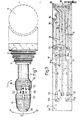
- Figure 1 is a longitudinal view of a control lever constructed in accordance with the present invention;
- Figure 2 is a longitudinal section through the control lever of Figure 1, to an enlarged scale;
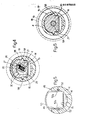
- Figure 3 is a plan view to an enlarged scale of one of the components of the control lever according to the invention; and
- Figures 4 to 8 are respective sections on the lines IV-IV, V-V, VI-VI, VII-VII and VIII-VIII of the lever of Figure 2.
- In Figure 1, the
reference numeral 1 indicates overall a control lever suitable for use on any control device of any known type for the signalling and/or operating devices of a vehicle, for example a motor vehicle, of any known type, not shown for simplicity. In particular, thelever 1 is arranged for connection to a control box 2 to be connected in its turn to the side of thesteering column 3 of said vehicle, and is arranged for rotation in the direction of the arrows relative to the box 2, to which it is hinged in known manner, in order in known manner to switch suitable control switches disposed in said box 2 and operating for example the vehicle direction indicators or vehicle windscreen and rear window wipers. In particular, according to the absolutely non-limiting example described hereinafter, thelever 1 is a control lever for the direction indicators, which are activated by rotating said lever relative to the box 2 from the position indicated by 0 to the positions indicated by A and B, and the box 2 contains internally a steering change release device of any known type, not shown for simplicity, and which can also be provided inside thesteering column 3 itself. - With reference also to Figure 2, the
lever 1 comprises an internally hollowcylindrical body 4 of substantially tubular shape open at one of its ends 5, and a connection element 7 formed integrally with thebody 4 at that end 6 of this latter which is opposite to the end 5, and which 18 closed by anend wall 8. The connection element 7 is substantially of lug configuration and is provided withhinging means 9 for hinging into said control box 2, which is arranged in its turn to support thelever 1 overall, and thebody 4 is preferably constructed of a plastics material by a suitable moulding operation. The end 6 is preferably also provided with aconnection groove 10 for a protection bellows 11 designed to cover the end 6. - According to the invention, the
body 4 of thelever 1 internally defines achamber 12 accessible from the outside, respectively through said open end 5 thereof and through a throughaperture 13 provided through said body 5 at the end 6. A printedcircuit 14, one embodi- sent of which can be seen in Figure 3, is housed in thechamber 12 and carries rigidly fixed on its upper face 15 a pair ofswitches 16, which are also housed in thechamber 12 and are disposed in an axial position corresponding torespective control rings body 4 and arranged, on rotation, to operate theswitches 16. These latter each comprise, with reference also to Figures 4, 6, 7 and 8, acasing 20 preferably of plastics construction, arotatable drum 21 idly housed in thecasing 20, a fixed contact board 22 (Figure 8) carried by a corresponding respective printedcircuit 23 forming part of theswitch 16 and disposed substantially orthogonal to the printedcircuit 14, a multiple sliding contact 24 (Figure 7) carried angularly rigid by thedrum 21 on thatface 25 thereof which faces the correspondingprinted circuit 23, and a position indicating device 26 (Figure 4) substantially of known type and comprising aball 27 housed, mobile against the action of a spring 28, in aseat 29 provided radially in thedrum 21 and a plurality of side-by-side cavities 30 provided in the inner surface of thecasing 20 in determined angular positions to be selectively snap-engaged by theball 27 under the thrust of the spring 28 in order to selectively halt thedrum 21 in a plurality of different angular positions corresponding to thevarious seats 30. Thecasing 20 is substantially of cup configuration and is closed lowerly by the printedcircuit 14, against theupper surface 15 of which it rests, and is closed at one end by the corresponding printedcircuit 23 which is fixed in any convenient manner to thecasing 20 and together with this latter supports thedrum 21. The slidingcontact 24 is arranged to slidably cooperate with the contact board provided on that surface of the printedcircuit 23 which faces thesurface 25 of thedrum 21, in such a manner as to make or break, according to the angular position of saiddrum 21 on the printedcircuit 23, one or more electrical circuits defined by thefixed contact board 22, which are electrically connected to corresponding conducting tracks 31 (Figure 3) carried by thesurface 15 of the printedcircuit 14, to which the printedcircuits 23 of theswitches 16 are rigidly fixed by respective connectors 32 (Figure 8) which are inserted and soldered intosuitable seats 33 of the printedcircuit 14. This latter comprises two respectiveopposing ends body 4 containing the printedcircuit 14, and at theend 35 is provided withcorresponding connection points 36 for corresponding electric cables 37 (Figure 2) for connection to the vehicle electrical circuit and which leave thechamber 12 through theaperture 13. Thecables 37 are preferably soldered to thecorresponding connection points 36, to which the respective conductingtracks 31 are connected, and converge at their free ends preferably into anelectrical connector 38 of any known type. Theaperture 13 is of such dimensions, according to the invention, as to enable it to be traversed by saidconnector 38, so that it is possible to slidably insert the printedcircuit 14 into thebody 4 after thecables 37 andswitches 16 have been premounted and fixed rigidly thereto, so that theconnector 38 emerges through theaperture 13, the end 5 being closed by suitable closure means in order to lock inside thebody 4 the printedcircuit 14 with all the elements carried thereby, so allowing extremely simple and rapid assembly of the entire electrical part of thelever 1. As shown in Figure 2, the printedcircuit 14 can have fixed and premounted on it not only theswitches 16, by way of their respective printedcircuits 23, and thecables 37, but also a furtherrespective press switch 39 complete with arespective control pushbutton 40 which can be snap-mounted in known manner on to theswitch 39, and one or more illumination devices 41a of LED or equivalent type. In particular, theswitch 39 is rigidly carried by acover 42 arranged to close the end 5 and be fixed rigidly thereto, and is also rigidly fixed to the printedcircuit 14 by respective connection pins 43 connected and soldered torespective connection seats 33a at theend 34, whereas theillumination LEDs 41 are disposed in the space between the pair of side-by-side switches 16 and are fixed to the printedcircuit 14 by means of their connection feet at respective connection points-36a on this latter circuit. Obviously all saidconnection points conducting tracks 31, so as to define on thesurface 15 of the printed circuit 14 a suitable electrical control circuit which on operation of theswitches LEDs 41 to light and, sore generally, to electrically connect thecables 37 together in order to either switch on or switch off the various electrical devices of the vehicle on which thelever 1 can be mounted and which are controllable by saidlever 1. - According to the invention, the
rings body 4, so as to be able to be mounted thereon by starting -from the end 5 and moving them towards the corresponding end 6, and are provided with correspondingelastic teeth 45 provided in respective suitable radiallyinternal cavities 46 of therings outer grooves 47 in thebody 4 which are provided in determined axial positions thereon in order to axially but removably lock therings underlying switches 16 carried by the printedcircuit 14 assume when this latter is inserted into thebody 4. Therings ring 19 being mounted on thebody 4 at the end 5 and comprising a terminal collar-shaped portion 48 which projects from thebody 4 to define a slide seat for thepushbutton 40 of theswitch 39. Thering 18 is disposed to the side of thering 19 on that side thereof facing the end 6 and at a predetermined distance therefrom, to define on thebody 4, together with this latter end, anannular portion 48 provided with athrough aperture 49 closed by atransparent panel 50 snap- fitted into correspondingaxial grooves 51, provided in the inner surface of thebody 4, by means of its respectiveelastic lugs 52. According to the invention, theaperture 49 is provided in a position corresponding with theillumination LEDs 41 carried by the underlying printedcircuit 14, and thetransparent panel 50 is provided with suitable diagrams, shown in Figure 1, the function of which is to identify which devices are controlled by the operation of theswitches 16. In order to enable thelever 1 to be made more compact, thecontrol pushbutton 40 is disposed substantially coaxially to and projecting from thebody 4, and substantially housed in thecollar portion 48 of thering 19, and thering 18 is provided with awindow 51, which allows observation of that portion of thetransparent panel 50 provided with said diagrams even with therings underlying switches 16 contained in thebody 4, by being fixed angularly rigid with thecorresponding drums 21 of theswitches 16 by means ofrespective pins 52 which radially traverse therings circumferential slots 53 provided through thebody 4 and theunderlying casings 20 of theswitches 16, and are then inserted into corresponding radial bores 54 in thedrums 21. Preferably, thepins 52 are formed integrally withrespective pointers 55 of transparent material construction which are carried in suitable seats in therings panel 50, and become illuminated, together with this latter, when theLEDs 41 are lit. - Finally according to the invention, the
casings 20 of theswitches 16 are provided laterally with respectivelongitudinal projections 58 arranged to slidably engage in thelongitudinal grooves 52 on thebody 4, together withcorresponding projections 58a on the printedcircuits 23. In this manner, as these latter and thecasings 20 are fixed rigidly to the printedcircuit 14, this can be bayonet-fitted into thebody 4 by inserting theprojections grooves 52 and then urging the printedcircuit 14 towards the end 6 until thecover 42, which has been previously fixed thereto together with theswitch 39, abuts against the end 5. - The ease with which the
lever 1 according to the invention is constructed and mounted are apparent from the description, as is its operation. Thebody 4, in a like manner to any control lever of known type, can be fixed on to the box 2 or directly on to thesteering column 3, for example rigid with a suitable steering change release device for the vehicle, by means of the connection element or lug 7, which is entirely identical to that of known levers, and consequently thebody 4 can undergo all the movements normally carried out by control levers of known type to operate the appropriate devices which are disposed in the box 2 in known manner, not shown for simplicity. Once thebody 4 has been installed on the vehicle, analogously to any control lever of known type, the entire electrical part can be inserted into it by a single operation as heretofore described, by firstly premounting the electrical part on the printedcircuit 14 by fixing to itssurface 15 theLEDs 41, theswitches 16, thecables 37 and theswitch 39 with itscover 42, and then bayonet-inserting the printedcircuit 14 into thechamber 12 by utilising thegrooves 52 andprojections 58. At this point thechamber 12 is closed by thecover 42, and the entire electrical part of thelever 1 is disposed inside saidchamber 12, with thecables 37 andconnector 38 hanging outside theaperture 13. Thus at this point, theconnector 38 can be connected to the vehicle electrical circuit and the connector and theaperture 13 then be completely covered with the protection bellows 11. Finally, firstly thering 18 and then thering 19 are mounted on thebody 4 by snapping theirteeth 45 into thegrooves 47, and thepushbutton 40 is mounted on theswitch 39 in order to close thecollar portion 48. Thepointers 55 are then mounted on therings pins 52 through saidslots 53 and inserting them into the bores 54, to thus angularly connect therings drums 21 of theswitches 16. It is consequently apparent that the user can operate the devices housed in the box 2 by simply manipulating thebody 4 which on being subjected to manual pressure by the user rotates on the lug or element 7, in known manner, for example in order to operate said steering change release device of the vehicle. Again, in order to operate the other vehicle electrical devices, for example the side position lights, the dipped Headlights and the emergency lights, the user has only to operate either thepushbutton 40 or one of the tworings switches 39 or Ib, with consequent activation of the selected devices. When the side position lights are lit, theLEDs 41 will also be activated to illuminate thetransparent panel 50 andpointers 55, thus enabling the user to perfectly determine the angular position of therings lever 1 according to the invention can be removed by firstly extracting thepointers 55, then therings pushbutton 40 and printedcircuit 14 after disconnecting theconnector 38. - The advantages of the present invention are apparent from the description, and it is also apparent that modifications can be made thereto without leaving the scope of the inventive idea.
Claims (9)
Applications Claiming Priority (2)
| Application Number | Priority Date | Filing Date | Title |
|---|---|---|---|
| IT67440/84A IT1179630B (en) | 1984-05-02 | 1984-05-02 | CONTROL LEVER FOR A COMMAND DEVICE FOR SIGNALING DEVICES AND VEHICLE OPERATORS |
| IT6744084 | 1984-05-02 |
Publications (2)
| Publication Number | Publication Date |
|---|---|
| EP0160905A1 true EP0160905A1 (en) | 1985-11-13 |
| EP0160905B1 EP0160905B1 (en) | 1987-11-04 |
Family
ID=11302398
Family Applications (1)
| Application Number | Title | Priority Date | Filing Date |
|---|---|---|---|
| EP85105128A Expired EP0160905B1 (en) | 1984-05-02 | 1985-04-26 | Control lever for a control device for vehicle signalling and/or operating devices |
Country Status (4)
| Country | Link |
|---|---|
| EP (1) | EP0160905B1 (en) |
| DE (1) | DE3560872D1 (en) |
| ES (1) | ES8607614A1 (en) |
| IT (1) | IT1179630B (en) |
Cited By (14)
| Publication number | Priority date | Publication date | Assignee | Title |
|---|---|---|---|---|
| EP0237499A1 (en) * | 1986-03-10 | 1987-09-16 | CAVIS CAVETTI ISOLATI S.p.A. | A switch stalk for a steering column |
| FR2636148A1 (en) * | 1988-09-08 | 1990-03-09 | Jaeger | CONTROLLER IN PARTICULAR FOR A MOTOR VEHICLE |
| EP0389366A1 (en) * | 1989-03-23 | 1990-09-26 | Jaeger | Actuating lever handle, particularly for motor vehicles, with two rotating rings |
| EP0446126A1 (en) * | 1990-03-06 | 1991-09-11 | Jaeger | Actuating lever handle with two rotating rings, particularly for automobile switches |
| GB2259609A (en) * | 1991-09-13 | 1993-03-17 | Asahi Optical Co Ltd | Switch |
| WO1996023677A1 (en) * | 1995-02-03 | 1996-08-08 | United Technologies Automotive, Inc. | Multifunction switch stalk |
| WO1998014349A1 (en) * | 1996-10-02 | 1998-04-09 | Itt Manufacturing Enterprises, Inc. | Microswitch device for control elements of vehicle commutation switches |
| DE19808547A1 (en) * | 1998-02-28 | 1999-09-02 | Itt Mfg Enterprises Inc | Steering column switch for the switching position describing coded switching signals |
| FR2796201A1 (en) * | 1999-07-08 | 2001-01-12 | Sc2N Sa | Switching control unit for driving position of car, has switch units driving electrical contacts, together with flexible printed circuit board defining electrical contacts |
| DE10056664A1 (en) * | 2000-11-10 | 2002-06-20 | Valeo Schalter & Sensoren Gmbh | Steering column switch for motor vehicles |
| EP1354763A2 (en) * | 2002-03-16 | 2003-10-22 | Delphi Technologies Inc. | Switch lever for a steering column switch of a vehicle |
| EP1374265A1 (en) * | 2001-04-02 | 2004-01-02 | Methode Electronics, Inc. | Steering column mounted multifunctional lever stalk switch assembly |
| WO2007140866A1 (en) * | 2006-06-09 | 2007-12-13 | Valeo Schalter Und Sensoren Gmbh | Steering column switch, in particular for motor vehicles |
| US10982754B2 (en) * | 2018-04-23 | 2021-04-20 | Ficosa International (Taicang) Co. Ltd. | Vehicle gear shift module |
Citations (1)
| Publication number | Priority date | Publication date | Assignee | Title |
|---|---|---|---|---|
| DE2835256A1 (en) * | 1978-08-11 | 1980-02-14 | Rau Swf Autozubehoer | Slide switch assembly on vehicle steering column - has bridge contacts operated by coupling which can be re leased |
-
1984
- 1984-05-02 IT IT67440/84A patent/IT1179630B/en active
-
1985
- 1985-04-26 DE DE8585105128T patent/DE3560872D1/en not_active Expired
- 1985-04-26 EP EP85105128A patent/EP0160905B1/en not_active Expired
- 1985-05-02 ES ES543279A patent/ES8607614A1/en not_active Expired
Patent Citations (1)
| Publication number | Priority date | Publication date | Assignee | Title |
|---|---|---|---|---|
| DE2835256A1 (en) * | 1978-08-11 | 1980-02-14 | Rau Swf Autozubehoer | Slide switch assembly on vehicle steering column - has bridge contacts operated by coupling which can be re leased |
Cited By (28)
| Publication number | Priority date | Publication date | Assignee | Title |
|---|---|---|---|---|
| EP0237499A1 (en) * | 1986-03-10 | 1987-09-16 | CAVIS CAVETTI ISOLATI S.p.A. | A switch stalk for a steering column |
| FR2636148A1 (en) * | 1988-09-08 | 1990-03-09 | Jaeger | CONTROLLER IN PARTICULAR FOR A MOTOR VEHICLE |
| EP0358570A1 (en) * | 1988-09-08 | 1990-03-14 | Jaeger | Actuating lever handle, particularly for a motor vehicle |
| US5003132A (en) * | 1988-09-08 | 1991-03-26 | Jaeger | Control lever for a motor vehicle |
| EP0389366A1 (en) * | 1989-03-23 | 1990-09-26 | Jaeger | Actuating lever handle, particularly for motor vehicles, with two rotating rings |
| FR2644928A1 (en) * | 1989-03-23 | 1990-09-28 | Jaeger | CONTROLLER IN PARTICULAR FOR MOTOR VEHICLES COMPRISING TWO ROTATING RINGS |
| EP0446126A1 (en) * | 1990-03-06 | 1991-09-11 | Jaeger | Actuating lever handle with two rotating rings, particularly for automobile switches |
| FR2659488A1 (en) * | 1990-03-06 | 1991-09-13 | Jaeger | CONTROL HANDLE WITH TWO ROTATING RINGS, PARTICULARLY FOR A SWITCH OF MOTOR VEHICLES. |
| GB2259609A (en) * | 1991-09-13 | 1993-03-17 | Asahi Optical Co Ltd | Switch |
| US5369230A (en) * | 1991-09-13 | 1994-11-29 | Asahi Kogaku Kogyo Kabushiki Kaisha | Switch apparatus |
| GB2259609B (en) * | 1991-09-13 | 1995-04-26 | Asahi Optical Co Ltd | Device having switch appratus |
| WO1996023677A1 (en) * | 1995-02-03 | 1996-08-08 | United Technologies Automotive, Inc. | Multifunction switch stalk |
| US5581058A (en) * | 1995-02-03 | 1996-12-03 | United Technologies Automotive, Inc. | Multifunction switch stalk for controlling vehicle functions |
| US5701660A (en) * | 1995-02-03 | 1997-12-30 | United Technologies Automotive Systems, Inc. | Method for making a multi-function switch stalk assembly |
| EP0914991A3 (en) * | 1995-02-03 | 2000-03-01 | Lear Automotive Dearborn, Inc. | Multifunction switch stalk |
| EP0914991A2 (en) | 1995-02-03 | 1999-05-12 | UNITED TECHNOLOGIES AUTOMOTIVE, Inc. | Multifunction switch stalk |
| WO1998014349A1 (en) * | 1996-10-02 | 1998-04-09 | Itt Manufacturing Enterprises, Inc. | Microswitch device for control elements of vehicle commutation switches |
| DE19808547A1 (en) * | 1998-02-28 | 1999-09-02 | Itt Mfg Enterprises Inc | Steering column switch for the switching position describing coded switching signals |
| FR2796201A1 (en) * | 1999-07-08 | 2001-01-12 | Sc2N Sa | Switching control unit for driving position of car, has switch units driving electrical contacts, together with flexible printed circuit board defining electrical contacts |
| DE10056664A1 (en) * | 2000-11-10 | 2002-06-20 | Valeo Schalter & Sensoren Gmbh | Steering column switch for motor vehicles |
| DE10056664B4 (en) * | 2000-11-10 | 2004-04-29 | Valeo Schalter Und Sensoren Gmbh | Steering column switch for motor vehicles |
| EP1205349A3 (en) * | 2000-11-10 | 2007-04-04 | Valeo Schalter und Sensoren GmbH | Steering column switch |
| EP1374265A1 (en) * | 2001-04-02 | 2004-01-02 | Methode Electronics, Inc. | Steering column mounted multifunctional lever stalk switch assembly |
| EP1374265A4 (en) * | 2001-04-02 | 2007-05-09 | Methode Electronics Inc | Steering column mounted multifunctional lever stalk switch assembly |
| EP1354763A2 (en) * | 2002-03-16 | 2003-10-22 | Delphi Technologies Inc. | Switch lever for a steering column switch of a vehicle |
| EP1354763A3 (en) * | 2002-03-16 | 2006-05-10 | Delphi Technologies Inc. | Switch lever for a steering column switch of a vehicle |
| WO2007140866A1 (en) * | 2006-06-09 | 2007-12-13 | Valeo Schalter Und Sensoren Gmbh | Steering column switch, in particular for motor vehicles |
| US10982754B2 (en) * | 2018-04-23 | 2021-04-20 | Ficosa International (Taicang) Co. Ltd. | Vehicle gear shift module |
Also Published As
| Publication number | Publication date |
|---|---|
| DE3560872D1 (en) | 1987-12-10 |
| IT1179630B (en) | 1987-09-16 |
| ES543279A0 (en) | 1986-06-01 |
| IT8467440A0 (en) | 1984-05-02 |
| ES8607614A1 (en) | 1986-06-01 |
| IT8467440A1 (en) | 1985-11-02 |
| EP0160905B1 (en) | 1987-11-04 |
Similar Documents
| Publication | Publication Date | Title |
|---|---|---|
| EP0160905A1 (en) | Control lever for a control device for vehicle signalling and/or operating devices | |
| US5736696A (en) | Combined automotive light switch | |
| US4277658A (en) | Steering column switch assembly | |
| CN101359546B (en) | Rotary switch for a motor vehicle | |
| US7514643B1 (en) | Lighted pushbutton switch assembly | |
| EP0637044A2 (en) | Illuminated rotary switch assembly | |
| US4179592A (en) | Signal switch assembly | |
| JP3678461B2 (en) | Electrical equipment | |
| US6570105B1 (en) | Retractable rotary switch cell | |
| US5854458A (en) | Stalk mounted three function switch assembly having a single multiplexed output | |
| US6403900B2 (en) | Compact steering column module | |
| US3610860A (en) | Electrical switches incorporating position-indicating means | |
| JP2002530831A (en) | Switching device | |
| KR100302042B1 (en) | Module-pitman arm switch unit | |
| US3394403A (en) | Lighted pushbutton assembly | |
| US7495187B2 (en) | Electrical switch | |
| JP3649637B2 (en) | Illumination structure of electronic equipment | |
| JPS59194225A (en) | Hand wheel assembly | |
| JP2003162943A (en) | Structure of vehicle lever switch | |
| EP0579882B1 (en) | Indicator | |
| US2215229A (en) | Automobile signal switch | |
| JP4063753B2 (en) | Joystick type input device | |
| US6087601A (en) | Modular multi-purpose switch | |
| US3281549A (en) | Combination lock and switch | |
| US20020139648A1 (en) | Multifunctional lever stalk |
Legal Events
| Date | Code | Title | Description |
|---|---|---|---|
| PUAI | Public reference made under article 153(3) epc to a published international application that has entered the european phase |
Free format text: ORIGINAL CODE: 0009012 |
|
| AK | Designated contracting states |
Designated state(s): DE FR GB SE |
|
| 17P | Request for examination filed |
Effective date: 19860121 |
|
| 17Q | First examination report despatched |
Effective date: 19860807 |
|
| GRAA | (expected) grant |
Free format text: ORIGINAL CODE: 0009210 |
|
| AK | Designated contracting states |
Kind code of ref document: B1 Designated state(s): DE FR GB SE |
|
| ET | Fr: translation filed | ||
| REF | Corresponds to: |
Ref document number: 3560872 Country of ref document: DE Date of ref document: 19871210 |
|
| PLBE | No opposition filed within time limit |
Free format text: ORIGINAL CODE: 0009261 |
|
| STAA | Information on the status of an ep patent application or granted ep patent |
Free format text: STATUS: NO OPPOSITION FILED WITHIN TIME LIMIT |
|
| 26N | No opposition filed | ||
| PGFP | Annual fee paid to national office [announced via postgrant information from national office to epo] |
Ref country code: SE Payment date: 19940330 Year of fee payment: 10 |
|
| PGFP | Annual fee paid to national office [announced via postgrant information from national office to epo] |
Ref country code: GB Payment date: 19940414 Year of fee payment: 10 |
|
| PGFP | Annual fee paid to national office [announced via postgrant information from national office to epo] |
Ref country code: DE Payment date: 19940502 Year of fee payment: 10 |
|
| EAL | Se: european patent in force in sweden |
Ref document number: 85105128.4 |
|
| PG25 | Lapsed in a contracting state [announced via postgrant information from national office to epo] |
Ref country code: GB Effective date: 19950426 |
|
| PG25 | Lapsed in a contracting state [announced via postgrant information from national office to epo] |
Ref country code: SE Effective date: 19950427 |
|
| GBPC | Gb: european patent ceased through non-payment of renewal fee |
Effective date: 19950426 |
|
| PG25 | Lapsed in a contracting state [announced via postgrant information from national office to epo] |
Ref country code: DE Effective date: 19960103 |
|
| EUG | Se: european patent has lapsed |
Ref document number: 85105128.4 |
|
| PGFP | Annual fee paid to national office [announced via postgrant information from national office to epo] |
Ref country code: FR Payment date: 19960412 Year of fee payment: 12 |
|
| PG25 | Lapsed in a contracting state [announced via postgrant information from national office to epo] |
Ref country code: FR Free format text: LAPSE BECAUSE OF NON-PAYMENT OF DUE FEES Effective date: 19971231 |
|
| REG | Reference to a national code |
Ref country code: FR Ref legal event code: ST |