EP0159827A2 - Verfahren und Vorrichtung zum Brechen eines Bohrgestänges beim Bohren - Google Patents
Verfahren und Vorrichtung zum Brechen eines Bohrgestänges beim Bohren Download PDFInfo
- Publication number
- EP0159827A2 EP0159827A2 EP85302158A EP85302158A EP0159827A2 EP 0159827 A2 EP0159827 A2 EP 0159827A2 EP 85302158 A EP85302158 A EP 85302158A EP 85302158 A EP85302158 A EP 85302158A EP 0159827 A2 EP0159827 A2 EP 0159827A2
- Authority
- EP
- European Patent Office
- Prior art keywords
- drill string
- gas
- drilling fluid
- drill
- compressed gas
- Prior art date
- Legal status (The legal status is an assumption and is not a legal conclusion. Google has not performed a legal analysis and makes no representation as to the accuracy of the status listed.)
- Withdrawn
Links
- 238000005553 drilling Methods 0.000 title claims abstract description 130
- 238000000034 method Methods 0.000 title claims description 20
- 239000012530 fluid Substances 0.000 claims abstract description 92
- 238000005520 cutting process Methods 0.000 claims abstract description 7
- 238000002347 injection Methods 0.000 claims description 8
- 239000007924 injection Substances 0.000 claims description 8
- 239000007788 liquid Substances 0.000 claims description 8
- 230000015572 biosynthetic process Effects 0.000 claims description 7
- 238000005755 formation reaction Methods 0.000 claims description 7
- 238000006073 displacement reaction Methods 0.000 claims description 6
- 238000013022 venting Methods 0.000 claims description 6
- 238000009408 flooring Methods 0.000 claims description 3
- 238000012544 monitoring process Methods 0.000 claims description 2
- 230000005587 bubbling Effects 0.000 claims 1
- 239000007789 gas Substances 0.000 description 66
- IJGRMHOSHXDMSA-UHFFFAOYSA-N Atomic nitrogen Chemical compound N#N IJGRMHOSHXDMSA-UHFFFAOYSA-N 0.000 description 2
- VNWKTOKETHGBQD-UHFFFAOYSA-N methane Chemical compound C VNWKTOKETHGBQD-UHFFFAOYSA-N 0.000 description 2
- 230000002411 adverse Effects 0.000 description 1
- 230000006835 compression Effects 0.000 description 1
- 238000007906 compression Methods 0.000 description 1
- 238000011161 development Methods 0.000 description 1
- 230000018109 developmental process Effects 0.000 description 1
- 238000005516 engineering process Methods 0.000 description 1
- 238000003780 insertion Methods 0.000 description 1
- 230000037431 insertion Effects 0.000 description 1
- 239000003345 natural gas Substances 0.000 description 1
- 229910052757 nitrogen Inorganic materials 0.000 description 1
- 239000003129 oil well Substances 0.000 description 1
- XLYOFNOQVPJJNP-UHFFFAOYSA-N water Substances O XLYOFNOQVPJJNP-UHFFFAOYSA-N 0.000 description 1
- 238000004804 winding Methods 0.000 description 1
Images

Classifications
-
- E—FIXED CONSTRUCTIONS
- E21—EARTH OR ROCK DRILLING; MINING
- E21B—EARTH OR ROCK DRILLING; OBTAINING OIL, GAS, WATER, SOLUBLE OR MELTABLE MATERIALS OR A SLURRY OF MINERALS FROM WELLS
- E21B21/00—Methods or apparatus for flushing boreholes, e.g. by use of exhaust air from motor
- E21B21/08—Controlling or monitoring pressure or flow of drilling fluid, e.g. automatic filling of boreholes, automatic control of bottom pressure
-
- E—FIXED CONSTRUCTIONS
- E21—EARTH OR ROCK DRILLING; MINING
- E21B—EARTH OR ROCK DRILLING; OBTAINING OIL, GAS, WATER, SOLUBLE OR MELTABLE MATERIALS OR A SLURRY OF MINERALS FROM WELLS
- E21B19/00—Handling rods, casings, tubes or the like outside the borehole, e.g. in the derrick; Apparatus for feeding the rods or cables
- E21B19/16—Connecting or disconnecting pipe couplings or joints
-
- E—FIXED CONSTRUCTIONS
- E21—EARTH OR ROCK DRILLING; MINING
- E21B—EARTH OR ROCK DRILLING; OBTAINING OIL, GAS, WATER, SOLUBLE OR MELTABLE MATERIALS OR A SLURRY OF MINERALS FROM WELLS
- E21B21/00—Methods or apparatus for flushing boreholes, e.g. by use of exhaust air from motor
- E21B21/01—Arrangements for handling drilling fluids or cuttings outside the borehole, e.g. mud boxes
-
- E—FIXED CONSTRUCTIONS
- E21—EARTH OR ROCK DRILLING; MINING
- E21B—EARTH OR ROCK DRILLING; OBTAINING OIL, GAS, WATER, SOLUBLE OR MELTABLE MATERIALS OR A SLURRY OF MINERALS FROM WELLS
- E21B3/00—Rotary drilling
- E21B3/02—Surface drives for rotary drilling
- E21B3/022—Top drives
Definitions
- Drilling of oil wells has progressed from crude drilling rigs, to cable tool rigs, to the modern rotary drilling rigs.
- a power rotating means delivers torque to a drill pipe which turns a bit drilling a borehole into the subsurface formations.
- the drill pipe is raised and lowered in the borehole from support means affixed to a conventional drilling rig.
- Suspended over pulleys positioned at the upper end or top of the rig are a plurality of cables which support a traveling block.
- a swivel Suspended from the traveling block is a swivel. The swivel is secured to a kelly which supports the drill pipe.
- the kelly is square or hexagonal in cross section over a substantial portion of its length and fits in sliding relation through a rotary table in the rig floor.
- the rotary table driven by a suitable prime mover, serves to turn the kelly, thereby rotating the drill pipe. Due to the sliding fit between the kelly and the rotary table, the kelly slides downwardly through the rotary table as drilling progresses. While the power for rotating the kelly, and thus the drill pipe, is applied to the rotary table, the entire weight of the kelly and drill pipe is supported by the swivel which also functions to conduct drilling fluid to the kelly and drill pipe.
- Drilling fluid generally from a mud tank or mud pit, passes through a hose into the swivel, downward through the drill pipe, and out through openings in the drill bit into the borehole.
- the drilling fluid then circulates upward from the drill bit, carrying formation cuttings through the annulus between the drill pipe and the borehole wall to the surface of the earth where it returns to the mud tank or pit.
- the traveling block, swivel, and kelly are lowered or raised as needed by manipulation of the cables.
- Such a conventional drilling system is illustrated in U.S. Patent Nos. 3,235,014; 3,324,717; 3,417,830; and 4,114,435.
- the present invention provides the rotary drilling of a wellbore with a drill string, formed with a plurality of sections of drill pipe, and having a drill bit at the lower end thereof, the method of disconnecting and breaking out at least one section of drill pipe from said drill string at a select drill string joint with minimized drilling fluid spillage, comprising steps of pulling the drill string out of the wellbore until a select drill string joint is above the drilling rig floor, injecting compressed gas into the drill string to displace the drilling fluid in that portion of the drill string above said select drill string joint, stopping the injection of compressed gas into the drill string when the drilling fluid level has fallen below said select drill string joint, and breaking out that portion of the drill string above said selected drill string joint.
- the present invention provides a method for breaking out at least one section of a drill pipe from a drill string in a well drilling operation in which the drill string is supported from a drilling rig and has a drill bit affixed to its lower end for drilling into the subsurface formation below the drilling rig, comprising supplying rotary power to the top of the drill string, circulating drilling fluid through the drill string to clean the drill bit and the borehole of drill cuttings, pulling said drill string out of the borehole while continuing the supplying of rotary power or the circulating of drilling fluid until a select drill string joint which is to be broken for the removal of at least one drill pipe section from the drill string is above the rig flooring, terminating the circulating of drilling fluid, injecting compressed gas into the top of said drill string to displace the drilling fluid downwardly through the drill string, monitoring the downward displacement of the drilling fluid through the drill string, terminating the injecting of compressed gas when the drilling fluid has been displaced downwardly through the drill string to a position below the select drill string joint at which said at least one drill pipe
- the present invent i provides a well drilling system wherein a power rotating means delivers torque to rotate a drill string suspended from a traveling block moving in response to movement of a cable arranged over multiple sheaves mounted in a crown block, the drill string turns a bit drilling a borehole into subsurface formations and a drilling fluid is circulated to keep the bit and bottom of the borehole cleaned of cuttings, a system for breaking out a portion of the drill string which has been pulled out of the well after drilling operations, comprising a source of compressed gas, a first valve which injects the compressed gas into the drill string when opened, means for sensing the level of the drilling fluid in the drill string as the compressed gas displaces the drilling fluid, means for closing said first valve to stop the injection of compressed gas into the drill string when the sensing means indicates the drilling fluid level to be below that portion of the drill string which is to be broken out, a second valve which is opened following the closing of said first valve to vent the compressed gas from the drill string, and means for breaking out said portion of the drill string upon
- top drive drilling system over the kelly and rotary table drilling system is the ability to rotate the drill pipe and circulate the drilling fluid when tripping in or out of the borehole.
- This ability to rotate and circulate at any time while tripping provides significant time savings, especially where the potential for preventing sticking of the drill pipe in tight sections or high angle boreholes is greatly increased.
- each section of drill pipe will be wet, that is full of mud, at breakout.
- a stand of three sections of drill pipe, normally in 10 meter sections, is tripped out of the borehole and the bottom joint of the stand broken, considerable drilling fluid spillage from the broken connection onto the rig floor can be expected.
- a 30 meter stand of 10 cm inside diameter drill pipe contains as much as about 0.24 m 3 of drilling fluid, usually a drilling mud.
- drilling fluid usually a drilling mud.
- special containers i.e., mud boxes or mud buckets
- the resulting mud spillage can cause loss of time, severe safety hazards, bad working conditions, inefficiency and loss of expensive mud.
- These adverse conditions are amplified by the use of oil-base muds. It is therefore the specific feature of the present invention to provide for a method and system by which such mud spillage is completely avoided when drilling with a top drive drill system, such invention being hereinafter described in conjunction with FIGS. 1 and 2.
- a drill string 17 is suspended within the well 10, and includes, at its lower end, a plurality of drill collars 11 and a drill bit 12.
- the drill string 17 is held in tension and only the weight of the drill collars 11 or less is allowed on the drill bit 12.
- the traveling block is moved by multiple windings of cable 23 between it and a crown block 24.
- One end of the cable 23, the so-called “dead line,” is held by a dead line anchor 26.
- the other end of the cable 23 is fastened to the drum 25 of the drawworks and is wound onto it by rotation of that drum.
- the traveling block 22 is raised or lowered to take more or less of the weight of the drill collar 11.
- a drilling fluid from a mud tank or pit 15 is circulated by a drilling fluid pump 14 through the line 18 into the swivel 31 and hence, into the drill string 17.
- the drilling fluid flows down through the drill string 17 and out through openings in the drill bit 12 into the well 10.
- the drilling fluid then circulates upward from the drill bit 12, carrying formation cuttings through the annulus between the drill string 17 and the well 10 to the surface of the earth.
- a line 16 returns the drilling fluid from the well 10 to the pit 15.
- the drill string 17 is illustrated as being pulled out of the well during tripping operations such that a stand 39 of three drill pipe sections 40-42 are above the rig floor 43. At this point, the stand 39 is to be broken out of the drill string 17 at the joint 44. However, drilling fluid fills the entire stand 39 and will spill out onto the rig floor when the joint 44 is broken.
- a conventional 30 meter stand of 10 cm ID (4 inch) drill pipe has a capacity of 0.22 m 3 (1.4 barrels) of drilling fluid which amounts to as much as 25 m 3 (1 5 5 barrels) of drilling fluid in tripping out of a well from 3,000 m (10,000 feet).
- the stand 39 of drill pipe is to be broken out from the drill string 17 at the joint 44 just above the slips 50 in the rig floor 43.
- mud circulation through inlet line 52 and return line 53 is stopped, valve 59 is opened, and compressed gas is forced into line 52 through valve 59 to displace the drilling fluid in the stand 39.
- a liquid level sensor 55 or other alternative means, is utilized to determine when the drilling fluid has been completely displaced from the stand 39. At this time the compressed gas is vented from the drill string 39 and the drill string joint 44 is broken without any significant drilling fluid spillage.
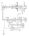
- FIG. 2 An automated system for controlling the supply of compressed gas to the stand 39 is also shown in FIG. 2.
- a gas source 60 supplies a compressor 61. Air would be the preferred gas unless the nature of the drilling fluid is such that the presence of air creates a problem. Natural gas and nitrogen are suitable alternatives.
- the gas is stored in a compressed gas storage tank 62.
- Gas source 60 and compressor 61 may be combined into a single unit such as a compressed gas cyclinder or cylinders. About 5 .4 standard m 3 (190 SCF) of compressed gas at 2,200 kPa (300 psig) pressure will be required to displace the drilling fluid from a 30 meter stand of 10 cm (4 inch) inside diameter drill pipe.
- a signal is sent by way of line 63 from control unit 64 to a valve 65.
- This signal causes valve 65, which is otherwise closed, to open and supply compressed gas through a mud separator 66 and valve 59 to the swivel 31.
- the mud separator 66 functions when the compressed gas is vented out of the stand 39 and will be described later on.
- the level to which the drilling fluid is displaced is not important only so long as it is below joint 44.
- a liquid level sensor 55 is illustrated adjacent the drill string below the rig flooring 43.
- control unit 64 When the drilling fluid level reaches this point, sensor 55 sends a signal over line 67 to the control unit 64 which operates to close valve 65 and shut off the supply of compressed gas to stand 39. At the same time, control unit 64 sends a signal over line 68 to open the otherwise closed valve 69. This allows the gas to be vented out of the top of stand 39, through valve 59, mud separator 66 and valve 69 into a gas holding tank 70. As mentioned earlier, the drilling fluid has been displaced from stand 39 excepting for some residue film that clings to the inside walls of the drill pipe. Some of this residue may be carried out of the top of stand 39 along with the venting of the gas.
- mud separator 66 It is the function of mud separator 66 to separate out this drilling fluid so that only the gas is vented all the way to the gas holding tank 70.
- Compressor 61 begins to recompress the vented gas, now in gas holding tank 70.
- the recompressed gas is stored in gas storage 62 for subsequent use with a later drill stand breakout operation.
- the gas holding tank 70 is a conventional bell-type holder as shown in FIG. 3.
- a first tank 71 has inserted within it a second inverted tank or bell tank 72.
- the first tank 71 is filled with a liquid, preferably water, to a level as shown in FIG. 3.
- the bell tank begins to rise and opens the otherwise closed liquid level switch 73.
- This signals the control unit 64 over line 74, which in turn, signals compressor 61 over line 75 to load, i.e. start recompressing the vented gas now being collected.
- the bell tank 72 has lowered to a position to close switch 73. This signals control unit 64 to unload compressor 61 since all the vented gas has now been compressed.
- a liquid level sensor 55 has been illustrated for detecting when the drilling fluid has been displaced below the drill stand breakout point at joint 44.
- One such sensor may be a conventional mechanical-sonic type sensor which uses an electromechanical device to strike the drill string 17 on one side while a sonic sensor on the other side of the drill string monitors the sound frequency or intensity to detect the passage of the drilling fluid level.
- Another liquid level sensor that would be suitable is set forth in U.S. Patent No. 4,391,135 to Godbey et. al. This sensor would be positoned at the top of the stand 39, as shown at 77.
- Acoustic pressure pulses are transmitted from sensor 77 down the drill pipe and reflected by the drilling fluid level 51. The travel time of the reflected pulses is measured by the sensor 77 as an indication of the depth to which the drilling fluid has been displaced.
- An alternative method to that of measuring the depth of the drilling fluid level 51 is to measure the volume of the displacing compressed gas required to lower the drilling fluid level below the breakout joint 44 of the 30 meter stand 39 of drill pipe.
- a pressure sensor 78 monitors the pressure of the compressed gas in the gas storage unit 62. During displacement of the drilling fluid, the pressure in gas storage unit is lowered. Since the volume of the gas storage unit is known, the final pressure expected upon complete displacement of the drilling fluid from the 30 meter stand 39 of drill pipe can be predetermined. When pressure sensor 78 reaches this predetermined pressure, control unit 64 operates to close valve 65 and terminate the drilling fluid displacement operation.
- the drilling fluid displacement operation described above in conjunction with FIG. 2 relates to injecting compressed gas into the top of the stand 39 of drill pipe such that such gas acts with a piston-like force on the top of the column of drilling fluid, thereby lowering its level so long as the injection of compressed gas continues.
- An alternative method to this above-described method involves the insertion of a tube through the top of stand 39 to a point below the breakout joint 44 as shown by the dotted lines at 80.
- the compressed gas is forced through the tube 39 into the drilling fluid below joint 44.
- the gas then bubbles up through the fluid, thereby reducing fluid density and lowering the level of the fluid.
- Such gas injection continues until the fluid level is identified as falling below the joint 44 by one of the several above-described liquid level sensing methods.
Landscapes
- Engineering & Computer Science (AREA)
- Geology (AREA)
- Life Sciences & Earth Sciences (AREA)
- Mining & Mineral Resources (AREA)
- Physics & Mathematics (AREA)
- Environmental & Geological Engineering (AREA)
- Fluid Mechanics (AREA)
- Mechanical Engineering (AREA)
- General Life Sciences & Earth Sciences (AREA)
- Geochemistry & Mineralogy (AREA)
- Earth Drilling (AREA)
- Drilling Tools (AREA)
- Perforating, Stamping-Out Or Severing By Means Other Than Cutting (AREA)
- Treatment Of Fiber Materials (AREA)
Applications Claiming Priority (2)
| Application Number | Priority Date | Filing Date | Title |
|---|---|---|---|
| US600698 | 1984-04-16 | ||
| US06/600,698 US4577700A (en) | 1984-04-16 | 1984-04-16 | Method and system for displacing drilling fluid from a drill string in a well drilling system |
Publications (2)
| Publication Number | Publication Date |
|---|---|
| EP0159827A2 true EP0159827A2 (de) | 1985-10-30 |
| EP0159827A3 EP0159827A3 (de) | 1987-10-28 |
Family
ID=24404710
Family Applications (1)
| Application Number | Title | Priority Date | Filing Date |
|---|---|---|---|
| EP85302158A Withdrawn EP0159827A3 (de) | 1984-04-16 | 1985-03-28 | Verfahren und Vorrichtung zum Brechen eines Bohrgestänges beim Bohren |
Country Status (4)
| Country | Link |
|---|---|
| US (1) | US4577700A (de) |
| EP (1) | EP0159827A3 (de) |
| CA (1) | CA1240982A (de) |
| NO (1) | NO851502L (de) |
Cited By (1)
| Publication number | Priority date | Publication date | Assignee | Title |
|---|---|---|---|---|
| CN118292781A (zh) * | 2024-05-14 | 2024-07-05 | 中国南海--麦克巴泥浆有限公司 | 一种油田钻井液定量注入与优化装置及方法 |
Families Citing this family (13)
| Publication number | Priority date | Publication date | Assignee | Title |
|---|---|---|---|---|
| JPH085136B2 (ja) * | 1989-04-11 | 1996-01-24 | デズグロウ・ピーティーワイ・リミテッド | グラスファイバー製品製造用の型板 |
| CA2188839C (en) * | 1996-10-25 | 2001-01-02 | David Speed | Recovery of gas from drilling fluid returns in underbalanced drilling |
| US6378628B1 (en) * | 1998-05-26 | 2002-04-30 | Mcguire Louis L. | Monitoring system for drilling operations |
| US7270185B2 (en) * | 1998-07-15 | 2007-09-18 | Baker Hughes Incorporated | Drilling system and method for controlling equivalent circulating density during drilling of wellbores |
| US6457529B2 (en) * | 2000-02-17 | 2002-10-01 | Abb Vetco Gray Inc. | Apparatus and method for returning drilling fluid from a subsea wellbore |
| US7182133B2 (en) * | 2002-02-04 | 2007-02-27 | Frank's Casing Crew And Rental Tools, Inc. | Elevator sensor |
| US6651745B1 (en) * | 2002-05-02 | 2003-11-25 | Union Oil Company Of California | Subsea riser separator system |
| US7003204B2 (en) * | 2003-08-07 | 2006-02-21 | Northrop Grumman Corporation | Systems and methods for a continuously variable optical delay line |
| CN102305021B (zh) * | 2011-08-04 | 2013-04-10 | 西南石油大学 | 一种模拟空气钻井井下钻具动态力学特征的实验方法 |
| CN102877782A (zh) * | 2012-09-27 | 2013-01-16 | 三一重工股份有限公司 | 旋挖钻机和卤水采集方法 |
| CN104047590B (zh) * | 2014-06-20 | 2016-05-18 | 盘锦春亚石油科技有限公司 | 采用井控工程监测系统对井控工程检测的方法 |
| GB2555236B (en) * | 2015-05-15 | 2021-04-14 | Halliburton Energy Services Inc | Methods, apparatus, and systems for injecting and detecting compositions in drilling fluid systems |
| US11220871B2 (en) * | 2019-11-11 | 2022-01-11 | Ronald Thorsten Eckmann | Methods for cleaning drill pipe during trip-out |
Family Cites Families (10)
| Publication number | Priority date | Publication date | Assignee | Title |
|---|---|---|---|---|
| US2120132A (en) * | 1936-12-23 | 1938-06-07 | Texas Co | Method and apparatus for cleaning wells |
| US2595715A (en) * | 1947-01-28 | 1952-05-06 | John H Poe | Method of and apparatus for expediting the drilling of wells |
| US2832566A (en) * | 1953-04-10 | 1958-04-29 | Exxon Research Engineering Co | Method for maintaining level of drilling fluid |
| US3053330A (en) * | 1961-01-18 | 1962-09-11 | Glen H Arthur | Hydraulically operated power swivel |
| SE381081B (sv) * | 1972-08-07 | 1975-11-24 | Atlas Copco Ab | Driftpreventer for astadkommande av tetning mellan borrstreng och ett foderror vid djuphalsborrning under overtryck |
| US3963077A (en) * | 1975-06-18 | 1976-06-15 | Faulkner Ben V | Method of preventing well bore drilling fluid overflow and formation fluid blowouts |
| US4162473A (en) * | 1978-02-13 | 1979-07-24 | Dresser Industries, Inc. | Drilling mud level measurement |
| US4391135A (en) * | 1980-04-14 | 1983-07-05 | Mobil Oil Corporation | Automatic liquid level monitor |
| US4315553A (en) * | 1980-08-25 | 1982-02-16 | Stallings Jimmie L | Continuous circulation apparatus for air drilling well bore operations |
| US4394880A (en) * | 1980-10-31 | 1983-07-26 | Faulkner Ben V | Method of preventing drill string overflow |
-
1984
- 1984-04-16 US US06/600,698 patent/US4577700A/en not_active Expired - Fee Related
-
1985
- 1985-03-28 EP EP85302158A patent/EP0159827A3/de not_active Withdrawn
- 1985-04-03 CA CA000478280A patent/CA1240982A/en not_active Expired
- 1985-04-15 NO NO851502A patent/NO851502L/no unknown
Cited By (1)
| Publication number | Priority date | Publication date | Assignee | Title |
|---|---|---|---|---|
| CN118292781A (zh) * | 2024-05-14 | 2024-07-05 | 中国南海--麦克巴泥浆有限公司 | 一种油田钻井液定量注入与优化装置及方法 |
Also Published As
| Publication number | Publication date |
|---|---|
| NO851502L (no) | 1985-10-17 |
| EP0159827A3 (de) | 1987-10-28 |
| US4577700A (en) | 1986-03-25 |
| CA1240982A (en) | 1988-08-23 |
Similar Documents
| Publication | Publication Date | Title |
|---|---|---|
| US4577700A (en) | Method and system for displacing drilling fluid from a drill string in a well drilling system | |
| US4544041A (en) | Well casing inserting and well bore drilling method and means | |
| US7066283B2 (en) | Reverse circulation directional and horizontal drilling using concentric coil tubing | |
| US7044239B2 (en) | System and method for automatic drilling to maintain equivalent circulating density at a preferred value | |
| US2929610A (en) | Drilling | |
| US9677337B2 (en) | Testing while fracturing while drilling | |
| RU2496966C2 (ru) | Подъемный инструмент с клиновыми захватами для подъема компоновки низа бурильной колонны во время операций бурения на обсадной колонне | |
| RU2378479C2 (ru) | Способ и устройство для выполнения операций в стволе подземной скважины посредством использования гибких обсадных труб | |
| US20110280104A1 (en) | Dual top drive systems and methods for wellbore operations | |
| US3081828A (en) | Method and apparatus for producing cuts within a bore hole | |
| US7677329B2 (en) | Method and device for controlling drilling fluid pressure | |
| US7950463B2 (en) | Method and arrangement for removing soils, particles or fluids from the seabed or from great sea depths | |
| CN101952545A (zh) | 用于在对地下地层进行钻进期间对其进行压裂的方法和系统 | |
| CA2725202A1 (en) | Circulation system for retrieval of bottom hole assembly during casing while drilling operations | |
| WO2012003101A2 (en) | System and method for controlling wellbore pressure | |
| EP1423582A1 (de) | Anordnung zum bohren einer niederdruckformation | |
| AU2002339535A1 (en) | Assembly for drilling low pressure formation | |
| US4646855A (en) | Method for raising and lowering a drill string in a wellbore during drilling operations | |
| US4643264A (en) | Method for reducing drilling torque in the drilling of a deviated wellbore | |
| US4223870A (en) | Bailer for top head drive rotary well drills | |
| RU2472901C1 (ru) | Водозаборный трубчатый колодец и устройство для его сооружения | |
| US10550653B2 (en) | Air storage system | |
| US11719058B2 (en) | System and method to conduct underbalanced drilling | |
| GB2598912A (en) | Drill rig tube delivery apparatus and method | |
| US2107556A (en) | Drilling mechanism |
Legal Events
| Date | Code | Title | Description |
|---|---|---|---|
| PUAI | Public reference made under article 153(3) epc to a published international application that has entered the european phase |
Free format text: ORIGINAL CODE: 0009012 |
|
| AK | Designated contracting states |
Designated state(s): DE GB NL |
|
| PUAL | Search report despatched |
Free format text: ORIGINAL CODE: 0009013 |
|
| AK | Designated contracting states |
Kind code of ref document: A3 Designated state(s): DE GB NL |
|
| 17P | Request for examination filed |
Effective date: 19880331 |
|
| 17Q | First examination report despatched |
Effective date: 19890615 |
|
| STAA | Information on the status of an ep patent application or granted ep patent |
Free format text: STATUS: THE APPLICATION IS DEEMED TO BE WITHDRAWN |
|
| 18D | Application deemed to be withdrawn |
Effective date: 19910109 |
|
| RIN1 | Information on inventor provided before grant (corrected) |
Inventor name: SEXTON, JAMES HOWARD Inventor name: STRONG, ROBERT THOMAS Inventor name: DELLINGER, THOMAS BAYNES Inventor name: BOSTON, WILLIAM GRANVILLE |