EP0159613B1 - Device of conveying a stimulable phosphor sheet - Google Patents
Device of conveying a stimulable phosphor sheet Download PDFInfo
- Publication number
- EP0159613B1 EP0159613B1 EP85104263A EP85104263A EP0159613B1 EP 0159613 B1 EP0159613 B1 EP 0159613B1 EP 85104263 A EP85104263 A EP 85104263A EP 85104263 A EP85104263 A EP 85104263A EP 0159613 B1 EP0159613 B1 EP 0159613B1
- Authority
- EP
- European Patent Office
- Prior art keywords
- stimulable phosphor
- sheet
- phosphor sheet
- conveying
- layer
- Prior art date
- Legal status (The legal status is an assumption and is not a legal conclusion. Google has not performed a legal analysis and makes no representation as to the accuracy of the status listed.)
- Expired - Lifetime
Links
Images


Classifications
-
- G—PHYSICS
- G21—NUCLEAR PHYSICS; NUCLEAR ENGINEERING
- G21K—TECHNIQUES FOR HANDLING PARTICLES OR IONISING RADIATION NOT OTHERWISE PROVIDED FOR; IRRADIATION DEVICES; GAMMA RAY OR X-RAY MICROSCOPES
- G21K4/00—Conversion screens for the conversion of the spatial distribution of X-rays or particle radiation into visible images, e.g. fluoroscopic screens
Definitions
- the present invention relates to a device for conveying a stimulable phosphor sheet employable in a radiation image recording and reproducing device, utilizing a stimulable phosphor.
- a radiation image recording and reproducing method utilizing a stimulable phosphor as described, for instance, in U.S. Patent No. 4,239,968, has been developed and paid much attention.
- the method involves steps of causing a stimulable phosphor to absorb a radiation having passed through an object or having radiated from an object; sequentially exciting (or scanning) the phosphor with an electromagnetic wave such as visible light or infrared rays (stimulating rays) to release the radiation energy stored in the phosphor as light emission (stimulated emission); photoelectrically detecting the emitted light to obtain electric signals; and reproducing the radiation image of the object as a visible image, numerals, symbols, etc. from the electric signals.
- the radiation image recording and reproducing method a radiation image is obtainable with a sufficient amount of information by applying a radiation to the object at a considerably smaller dose, as compared with the conventional radiography. Accordingly, the radiation image recording and reproducing method is of great value, especially when the method is used for medical diagnosis.
- a stimulable phosphor is generally employed in the form of a stimulable phosphor sheet (also referred to as a radiation image storage panel, and generally in the form of a sheet of rectangle, square, etc.) which comprises a support and a phosphor layer provided thereon.
- the phosphor layer comprises a stimulable phosphor and a binder.
- a protective film made of a transparent plastic film is provided on a surface of the phosphor layer to protect the phosphor layer from physical and chemical deterioration.
- the stimulable phosphor sheet does not serve to finally record image information, but only stores the information temporarily to provide the image or the like on an independently prepared final recording medium as described above. Accordingly, the stimulable phosphor sheet can be repeatedly used and such repeated use brings about economical advantage.
- the repeated use of the stimulable phosphor sheet is particularly advantageous, for instance, in the case that a radiation image information recording and reading device employing the stimulable phosphor sheet is mounted on a traveling station such as a radiographic apparatus-carryig car to conduct mass radiographic examination in various places. More in detail, it is inconvenient to carry a great number of stimulable phosphor sheets on a traveling station, and there is a limitation on the number of sheets capable of being carried on a car such as a radiographic apparatus-carrying car.
- the stimulable phosphor sheets are mounted on a radiographic car under such conditions that the stimulable phosphor sheets are repeatedly used; radiation image information of an object is recorded on each stimulable phosphor sheet and read out to obtain image information as a signal; and the obtained signal is transferred to a recording medium having a great recording capacity such as a magnetic tape so as to repeatedly use the stimulable phosphor sheet in cycle.
- a recording medium having a great recording capacity such as a magnetic tape
- the stimulable phosphor sheet In the case of performing repeated uses of the stimulable phosphor sheets in cycle, after the radiation energy stored in the stimulable phosphor sheet is read out and aimed image information is obtained, the remaining energy in the sheet is released and erased in a manner as disclosed, for instance, in Japanese Patent Provisional Publications No. 56(1981)-11392 and 56(1981)-12599. By employing such manner, the stimulable phosphor sheet can be efficiently and repeatedly used in cycle.
- the radiation image information recording and reading device in one aspect, is desirably mounted on a traveling station such as a radiographic apparatus-carrying car in the form of a united built-in device which comprises an image recording means for exposing a stimulable phosphor sheet to a radiation having passed through an object so as to record and store a radiation image in the stimulable phosphor sheet, a read-out means for reading out the radiation image stored in the stimulable phosphor sheet, an erasure means for releasing and erasing radiation energy remaining in the stimulable phosphor sheet for the next use of the stimulable phosphor sheet, and a conveyance means for moving the stimulable phosphor sheet in cycle to each of the above-mentioned means.
- the radiation image information recording and reading device having the above-mentioned constitution have various advantages not only in mounting in the traveling station such as a radiographic apparatus-carrying car but also in setting in hospitals, so that the above device is convenient in practical use.
- the radiation image information recording and reading device utilizing the above-mentioned system of repeatedly and cyclically using the stimulable phosphor sheet is disclosed in Japanese Patent Application No. 58(1983)-66730 filed in the present applicant (assignee).
- the stimulable phosphor sheet is occasionally conveyed vertically or almost vertically for the purpose of making the device compact.
- a stimulable phosphor sheet has physical deterioration such as a scratch on a surface thereof (a phosphor layer-side surface of the sheet), the quality of image or the accuracy of image information provided by the phosphor sheet tends to decrease markedly. For this reason, it is necessary to select the means for conveying a stimulable phosphor sheet with such a careful consideration that the surface of the stimulable phosphor sheet is not damaged. From this viewpoint, as a means for conveying a stimulable phosphor sheet, a belt conveyor made of a soft sheet-material is generally employed.
- the belt conveyor is suitable for conveying the stimulable phosphor sheet horizontally, it is unsuitable for conveying the stimulable phosphor sheet in the direction other than the horizontal direction, particularly in the vertical or almost vertical direction. More in detail, in the process for conveying a stimulable phosphor sheet vertically or almost vertically using a belt conveyor, it is necessary to arrange a pair of belt conveyors in such a manner that the belt conveyors are in face to face contact with each other so as to convey the stimulable phosphor sheet under the condition that the stimulable phosphor sheet is sandwiched between that pair of belt conveyors.
- said conveying device is complicated in structure, and it is difficult to make the device compact. Further, there are other problems such that the surface of the stimulable phosphor sheet tends to suffer scratches when the rate of one belt conveyor is made different from that of the other, even if the difference therebetween is very small.
- a device for conveying flat pieces like leaflets, letters or sheets.
- the device comprises a conveyor belt, which is guided by guiding rolls.
- additional conveying rolls are provided, which are pressed on the conveying belt and which are driven by the friction between the conveying belt and said conveying rolls.
- the distance between adjacent conveying rolls is shorter than the length of the sheet like material.
- Guiding rods are provided to prevent the sheet like material from being raised, for example, by an air stream from the conveying belt.
- the present invention has the object to provide a device for conveying stimulable phosphor sheets in a vertical direction, without deteriorating the phosphor layer and without allowing disorientation of the phosphor sheets.
- the method of conveying a stimulable phosphor sheet of the present invention comprises applying a driving force to a surface of the stimulable phosphor sheet by means of a driving member, keeping both side of said phosphor sheet by means of a guiding member to move the stimulable phosphor sheet in a given direction.
- the above-described method of conveying a stimulable phosphor sheet is effectively performed by utilizing the inventive device comprising a guiding member for keeping both sides of said stimulable phosphor sheet and two or more driving members arranged along the conveying direction for applying a driving force to a surface of said phosphor sheet, the distance between two driving members adjoining each other along the conveying direction being smaller than the length of said stimulable phosphor sheet measured in the conveying direction.
- the general constitution of the conventional stimulable phosphor sheet which is an object of the conveyance in the present invention is well known.
- the stimulable phosphor sheet is generally employed, as described above, in the form of a sheet comprising a support and a phosphor layer provided thereon which comprises a stimulable phosphor and a binder.
- a protective film of a transparent plastic material On the surface of the phosphor layer is provided a protective film of a transparent plastic material, because the phosphor layer is easily affected by physical shocks.
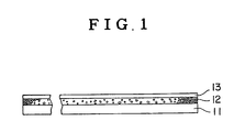
- Fig. 1 schematically illustrates the constitution of the conventional stimulable phosphor sheet.
- the stimulable phosphor sheet comprises a support 11, a phosphor layer 12 and a protective film 13.
- the support material include plastic films such as films of cellulose acetate and polyethylene terephthalate, metal sheets such as aluminum foil, ordinary papers, baryta paper, and resin-coated papers.
- On the surface of the support may be provided other functional layers such as an adhesive layer, a light-reflecting layer and a light-absorbing layer.
- the phosphor layer essentially comprises stimulable phosphor particles dispersed in a binder.
- the stimulable phosphor employed in the invention can be selected from the known stimulable phosphors.
- Examples of the known stimulable phosphor include a divalent europium activated alkaline earth metal fluorohalide phosphor (M II FX:Eu2+, 6in which M II is at least one alkaline earth metal selected from the group consisting of Mg, Ca and Ba; and X is at least one halogen selected from the group consisting of Cl, Br, and I); an europium and samarium activated strontium sulfide phosphor (SrS:Eu,Sm); an europium and samarium activated lanthanum oxysulfide phosphor (La2O2S:Eu,Sm); an europium activated barium aluminate phosphor (BaO ⁇ Al2O3:Eu
- a transparent protective film is then provided on the surface of the phosphor layer to physically and chemically protect the phosphor layer.
- the material employable for the preparation of the transparent protective film include cellulose acetate, polymethyl methacrylate, polyethylene terephthalate and polyethylene.
- the transparent protective film generally has a thickness within the range of approx. 0.1 - 20 ⁇ m.
- the stimulable phosphor sheet can be colored with an appropriate colorant as described in U.S. Patent No. 4,394,581 and U.S. Patent Application No. 326,642. Further, white powder may be dispersed in the phosphor layer as described in U.S. Patent No. 4,350,893.
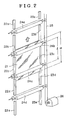
- FIGs. 2 and 3 [(1) and (2)] are schematic views of the conveying device which are preferably employed in the method of conveying a stimulable phosphor sheet according to the present invention.
- the method of conveying a stimulable phosphor sheet of the invention is described hereinafter, by referring to an embodiment employing the conveying devices shown in Figs. 2 and 3.
- the conveying device preferably employed in the method of conveying a stimulable phosphor sheet according to the invention is a device basically comprising guiding members 22 and 23 (22a, 23a, 22b, 23b, ...)[32 and 33 (32a, 33a, 32b, 33b, ...)] for keeping both sides of a stimulable phosphor sheet 21[31], and two or more driving members 24 (24a, 24b, 24c, ...)[34 (34a, 34b, 34c, ...)] arranged along the conveying direction (direction along the indicated arrow) for providing a driving force on both surfaces of the stimulable phosphor sheet 21[31], in which the distance between said two driving members which adjoin each other along the conveying direction (e.g., 24b and 24c)[e.g., 34b and 34c] is smaller than the length of the stimulable phosphor sheet measured in the conveying direction.
- the guiding members of the device according to the invention keep the stimulable phosphor sheet at the both sides thereof.
- the guiding members prevent the sheet from bending in the vertical direction against the surface plane of the sheet (namely, flexure) and from moving laterally.
- the guiding member is, U-shaped in the section. Accordingly, the guiding member is not necessarily in contact with the stimulable phosphor sheet to keep it.
- the surface of the sheet on which the radiation image is stored and recorded is kept being from contact with members of the device, since the stimulable phosphor sheet 21 is kept by the guiding members 22 and 23[32 and 33] at both sides of the sheet which do not participate in storing and recording the radiation image.
- the shape of the guiding member is not restricted to one as shown in Figs. 2 and 3, and any shape can be optionally used, as far as the guiding member has the above-described functions. Further, there is no specific limitation on the material of the guiding member.
- the guiding member is not necessarily employed in the form of individually separated member as shown in Figs. 2 and 3, and a united guiding member, for instance, a member in which one guiding member 22[32] is combined with another guiding member 23[33] on the back surface-side of the stimulable phosphor sheet 21[31] (support side-surface of the sheet) in Figs. 2 and 3, can be employed with appropriate selection of the driving members as described hereinafter.
- the driving members of the conveying device of the present invention apply a driving force to the surface(s) of the stimulable phosphor sheet, and make it possible to convey (i.e., move) the stimulable phosphor sheet in a given direction.
- the driving members comprises at least two members, and the distance (l) between the two driving members which are adjacent to each other along the conveying direction is smaller than the length (m) of the stimulable phosphor sheet in the conveying direction. Two or more driving members having the above-described constitution can convey the stimulable phosphor sheet with little error.
- the driving member for providing a driving force on the surfaces of the stimulable phosphor sheet are a driving member comprising a pair of rollers as shown in Figs. 2 and 3.
- the length of the roller is preferably as almost the same as width of the stimulable phosphor sheet (length measured in the lateral direction, but the length of the roller is not restricted to the above-mentioned length.
- the roller may comprise a plurality of short rollers.
- the driving member may not consist of a pair of rollers, and for example, a driving member comprising a driving roller and a fixed supporting member which is associated with the roller is employable. Further, other driving members than the above-mentioned rollers can be employed in the invention.
- the surface of the driving member especially the surface thereof which are to be in contact with the surface of the stimulable phosphor sheet, are preferably formed by a soft and elastic material such as rubber.
- a driving member having a surface of such material By employing a driving member having a surface of such material, the surface of the stimulable phosphor sheet can be protected from physical shock so as not to be damaged.
- the driving force is generally supplied to the driving members 24 (24a, 24b, 24c, ...)[24 (34a, 34b, 34c, ...)] from a means 26[37] such as a motor through a driving power-transmitting means 25[36] such as a chain and a belt. This driving force is then supplied to the stimulable phosphor sheet 21[31] under rotation via surfaces thereof.
- the guiding member and driving members are supported by an appropriate means such as a fixing means or a supporting means so as to fulfill each function in the area.
- the stimulable phosphor sheet can be easily and reliably conveyed in directions other than horizontal direction, particularly in the vertical or almost vertical direction (upward and/or downward conveying), without damaging the surfaces of the sheet.
- the vertical or almost vertical conveyance giving no damage to the surface of stimulable phosphor sheet has been hardly attained in the conventional method using a belt conveyor.
- the method of conveying the stimulable phosphor sheet of the invention can be effectively used not only in the conveyance of a stimulable phosphor sheet in the vertical or almost vertical direction but also in the conveyance with alteration of the direction (e.g. L-turn and U-turn).
- the method of the invention can be effectively employed in the conveyance of a stimulable phosphor sheet in the horizontal direction.
- a belt conveyor is conventionally used in the conveyance thereof in such direction.
- the method of the present invention can be employed in combination with a conventional method using a belt conveyor in conveying the stimulable phosphor sheet in a radiation image information recording and reading device.
- the device illustrared in the Fig. 3 is further provided with a guiding means 35 (35a, 35b, 35c, ...) for guiding the front end of the stimulable phosphor sheet.
- the guiding means 35 is arranged in the vicinity of the driving means 34, for instance, just in front of the driving means 34.
- the guiding means 35 serves to smoothly engage the coming stimulable phosphor sheet with the driving means.
- the stimulable phosphor sheet essentially comprising a support and a phosphor layer is considerably rigid, flexure may occasionally happen on most of the conventional stimulable phosphor sheet used in a relatively thin plate having a width of approx. 30 - 60 cm at the front end.
- the guiding means 35 for guiding the front end of the stimulable phosphor sheet is very effective to enable smooth engagement between the stimulable phosphor sheet and the driving means.
- the front end-guiding means can be in the form of a roller arranged in the vicinity of the driving means.
- the front end-guiding means can be arrange merely on one side of the conveyor.
- the front end-guiding means is generally made of plastic material, metal, or a composite material of plastic material and metal.
- the method of the invention is suitable for conveying a stimulable phosphor sheet in the vertical or almost vertical direction. Accordingly, from the viewpoint of making the device compact, the method of the invention can be preferably and practically employed in the radiation image information recording and reading device in which the stimulable phosphor sheet is required to be conveyed in such direction so as to be repeatedly used in cycle.
- Both sides of the stimulable phosphor sheet to be employed in the conveying method of the invention are preferably formed or processed to have enhanced protection against the physical (mechanical) shock given to these sides by the side-guiding means in the course of the conveying stage, as well as enhanced protection against chemical deterioration.
- Fig. 4a in which the support, phosphor layer and protective layer are indicated by 41, 42 and 43, respectively.
- a polymer coating layer as illustrated in Fig. 4b in which the support, phosphor layer, protective layer and polymer coating layer are indicated by 41, 42, 43 and 44, respectively.
- a polymer film as illustrated in Fig. 4c in which the support, phosphor layer. protective layer and polymer film are indicated by 41, 42, 43 and 45, respectively.
- the polymer film 45 is fixed to the side by an adhesive layer 46.
- a polymer coating layer as illustrated in Fig. 5a in which the support, phosphor layer, protective layer and polymer coating layer are indicated by 51, 52, 53 and 54, respectively.
- the side edges on the bottom surface of the support can be chamferred, as illustrated in Fig. 5b.
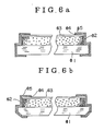
- a polymer film as illustrated in Fig. 6a in which the support, phosphor layer, protective layer and polymer film are indicated by 61, 62, 63 and 65, respectively.
- the polymer film 65 is fixed to the side by an adhesive layer 64.
- the side edges on the bottom surface of the support can be chamferred, as illustrated in Fig. 6b.
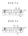
- a solid material fixedly placed in the area formed by the retraction of the phosphor layer as illustrated in Fig. 7a in which the support, phosphor layer, protective layer and solid material are indicated by 71, 72, 73 and 74, respectively.
- the side edges on the bottom surface of the support can be chamferred, as illustrated in Fig. 7b.
- a stimulable phosphor sheet may comprise a substrate, a support, a phosphor layer and a protective film superposed in this order, in which at least both sides of the phosphor layer and support along the direction to be conveyed are retracted from the corresponding side edges of the substrate, and both of said sides of the sheet are protected by a polymer coating layer.
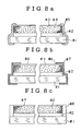
- Fig. 8a the substrate, support, phosphor layer, protective layer and polymer coating layer are indicated by 81, 82, 83, 84, and 85, respectively.
- the protection can be made by means of an adhesive layer 86 and a polymer film 87, as illustrated in Fig. 8b.
- the protection can be made by means of a solid material 88, as illustrated in Fig. 8c.
- the substrate can be produced from any material employable for the production of the support.
- the above-described protections can be given to the front and/or rear ends of the stimulable phosphor sheets, to protect the phosphor layer against physical shocks, as well as to keep the phosphor layer from chemical deterioration.
- the front and/or rear ends can be chamferred on the bottom surface.
- the sides of the protruded support or substrate can effectively keep the phosphor layer from physical shock, friction, and the like applied to the sides of the stimulable phosphor sheet.
- the polymer coating layer can be provided to the side of the stimulable phosphor sheet, for instance, by applying a solution of a film-forming polymer in a solvent to the side and then drying to remove the solvent, or applying reactive material(s) to form a polymer material to the side and causing the reaction to form in-situ the polymer coating film.
- a film-forming polymer employed in the above process.
- a polyurethane-acrylic resin and a mixture of an acrylic resin and vinyl chloride-vinyl acetate copolymer which is disclosed in Japanese Patent Provisional Publication 58(1983)-68746) can be used.
- the polymer film can be produced from the same material as that employed for the production of the protective material. For instance, cellulose acetate, polymethyl methacrylate, polyethylene terephthalate, and polyethylene can be mentioned.
- the polymer film employed for this purpose may be transparent or not.
- the film can be fixed to the side, for instance, by an adhesive or other sticky material.
- the solid material to be arranged adjacent to the side of the phosphor layer.
- a solid polymer material and a metal can be employed.
- the solid polymer material can be that menioned hereinbefore as the material for production of the surface protective film or a polymer film for protection of the side.
- the solid material can be provided adjacent to the side of the phosphor layer by placing it. Otherwise, a polymer material solution can be introduced in the area and the solid polymer can be formed in-situ after removal of the solvent. Otherwise, a solid polymer material can be formed in-situ by a reaction of reactive compound(s).
- the solid material can be fixed to the side of the phosphor layer and/or the upper surface of the support or substrate.
Description
- The present invention relates to a device for conveying a stimulable phosphor sheet employable in a radiation image recording and reproducing device, utilizing a stimulable phosphor.
- For obtaining a radiation image, there has been conventionally employed a radiography utilizing a combination of a radiographic film having a sensitive silver salt material layer and an intensifying screen.
- As a method replacing the above-mentioned conventional radiography, a radiation image recording and reproducing method utilizing a stimulable phosphor as described, for instance, in U.S. Patent No. 4,239,968, has been developed and paid much attention. The method involves steps of causing a stimulable phosphor to absorb a radiation having passed through an object or having radiated from an object; sequentially exciting (or scanning) the phosphor with an electromagnetic wave such as visible light or infrared rays (stimulating rays) to release the radiation energy stored in the phosphor as light emission (stimulated emission); photoelectrically detecting the emitted light to obtain electric signals; and reproducing the radiation image of the object as a visible image, numerals, symbols, etc. from the electric signals.
- In the radiation image recording and reproducing method, a radiation image is obtainable with a sufficient amount of information by applying a radiation to the object at a considerably smaller dose, as compared with the conventional radiography. Accordingly, the radiation image recording and reproducing method is of great value, especially when the method is used for medical diagnosis.
- In performing the radiation image recording and reproducing method, a stimulable phosphor is generally employed in the form of a stimulable phosphor sheet (also referred to as a radiation image storage panel, and generally in the form of a sheet of rectangle, square, etc.) which comprises a support and a phosphor layer provided thereon. The phosphor layer comprises a stimulable phosphor and a binder. Further, a protective film made of a transparent plastic film is provided on a surface of the phosphor layer to protect the phosphor layer from physical and chemical deterioration.
- The stimulable phosphor sheet does not serve to finally record image information, but only stores the information temporarily to provide the image or the like on an independently prepared final recording medium as described above. Accordingly, the stimulable phosphor sheet can be repeatedly used and such repeated use brings about economical advantage.
- The repeated use of the stimulable phosphor sheet is particularly advantageous, for instance, in the case that a radiation image information recording and reading device employing the stimulable phosphor sheet is mounted on a traveling station such as a radiographic apparatus-carryig car to conduct mass radiographic examination in various places. More in detail, it is inconvenient to carry a great number of stimulable phosphor sheets on a traveling station, and there is a limitation on the number of sheets capable of being carried on a car such as a radiographic apparatus-carrying car. Accordingly, it is practically useful that the stimulable phosphor sheets are mounted on a radiographic car under such conditions that the stimulable phosphor sheets are repeatedly used; radiation image information of an object is recorded on each stimulable phosphor sheet and read out to obtain image information as a signal; and the obtained signal is transferred to a recording medium having a great recording capacity such as a magnetic tape so as to repeatedly use the stimulable phosphor sheet in cycle. This means that radiation images of a number of objects can be obtained by the use of a small number of stimulable phosphor sheets. Further, the combination of the repeated uses of the stimulable phosphor sheets with a continuous radiographic process enables to perform rapid radiography in the mass radiographic examinations. This combination is of great value in practical use.
- In the case of performing repeated uses of the stimulable phosphor sheets in cycle, after the radiation energy stored in the stimulable phosphor sheet is read out and aimed image information is obtained, the remaining energy in the sheet is released and erased in a manner as disclosed, for instance, in Japanese Patent Provisional Publications No. 56(1981)-11392 and 56(1981)-12599. By employing such manner, the stimulable phosphor sheet can be efficiently and repeatedly used in cycle.
- Thus, the radiation image information recording and reading device, in one aspect, is desirably mounted on a traveling station such as a radiographic apparatus-carrying car in the form of a united built-in device which comprises an image recording means for exposing a stimulable phosphor sheet to a radiation having passed through an object so as to record and store a radiation image in the stimulable phosphor sheet, a read-out means for reading out the radiation image stored in the stimulable phosphor sheet, an erasure means for releasing and erasing radiation energy remaining in the stimulable phosphor sheet for the next use of the stimulable phosphor sheet, and a conveyance means for moving the stimulable phosphor sheet in cycle to each of the above-mentioned means. The radiation image information recording and reading device having the above-mentioned constitution have various advantages not only in mounting in the traveling station such as a radiographic apparatus-carrying car but also in setting in hospitals, so that the above device is convenient in practical use.
- The radiation image information recording and reading device utilizing the above-mentioned system of repeatedly and cyclically using the stimulable phosphor sheet is disclosed in Japanese Patent Application No. 58(1983)-66730 filed in the present applicant (assignee). In the device, the stimulable phosphor sheet is occasionally conveyed vertically or almost vertically for the purpose of making the device compact.
- If a stimulable phosphor sheet has physical deterioration such as a scratch on a surface thereof (a phosphor layer-side surface of the sheet), the quality of image or the accuracy of image information provided by the phosphor sheet tends to decrease markedly. For this reason, it is necessary to select the means for conveying a stimulable phosphor sheet with such a careful consideration that the surface of the stimulable phosphor sheet is not damaged. From this viewpoint, as a means for conveying a stimulable phosphor sheet, a belt conveyor made of a soft sheet-material is generally employed. However, while the belt conveyor is suitable for conveying the stimulable phosphor sheet horizontally, it is unsuitable for conveying the stimulable phosphor sheet in the direction other than the horizontal direction, particularly in the vertical or almost vertical direction. More in detail, in the process for conveying a stimulable phosphor sheet vertically or almost vertically using a belt conveyor, it is necessary to arrange a pair of belt conveyors in such a manner that the belt conveyors are in face to face contact with each other so as to convey the stimulable phosphor sheet under the condition that the stimulable phosphor sheet is sandwiched between that pair of belt conveyors. However, said conveying device is complicated in structure, and it is difficult to make the device compact. Further, there are other problems such that the surface of the stimulable phosphor sheet tends to suffer scratches when the rate of one belt conveyor is made different from that of the other, even if the difference therebetween is very small.
- A device according to the preamble of
claim 1 is disclosed in German Patent 444 581. This document relates to a device for conveying flat pieces like leaflets, letters or sheets. The device comprises a conveyor belt, which is guided by guiding rolls. In the section in which the conveyor belt is moved vertically, additional conveying rolls are provided, which are pressed on the conveying belt and which are driven by the friction between the conveying belt and said conveying rolls. The distance between adjacent conveying rolls is shorter than the length of the sheet like material. Guiding rods are provided to prevent the sheet like material from being raised, for example, by an air stream from the conveying belt. - The present invention has the object to provide a device for conveying stimulable phosphor sheets in a vertical direction, without deteriorating the phosphor layer and without allowing disorientation of the phosphor sheets.
- This object is solved by a device in accordance with
claim 1. Preferred embodiments of the device are subject matter of the sub claims. - The method of conveying a stimulable phosphor sheet of the present invention comprises applying a driving force to a surface of the stimulable phosphor sheet by means of a driving member, keeping both side of said phosphor sheet by means of a guiding member to move the stimulable phosphor sheet in a given direction.
- The above-described method of conveying a stimulable phosphor sheet is effectively performed by utilizing the inventive device comprising a guiding member for keeping both sides of said stimulable phosphor sheet and two or more driving members arranged along the conveying direction for applying a driving force to a surface of said phosphor sheet, the distance between two driving members adjoining each other along the conveying direction being smaller than the length of said stimulable phosphor sheet measured in the conveying direction.
-
- Fig. 1 is a schematic view illustrating the constitution of a conventional stimulable phosphor sheet, and
- Fig. 2 is a schematic view illustrating the constitution of the device preferably employed in the method of conveying a stimulable phosphor sheet according to the present invention.
- Fig. 3-(1) is a schematic view illustrating the constitution of another device preferably employed in the conveying method. Fig. 3-(2) is a side view of the device of Fig. 3-(1) seen along the indicated arrow A.
- Figs. 4a, 4b and 4c are schematic views illustrating the constitutions of embodiments of the stimulable phosphor sheet.
- Figs. 5a and 5b are schematic views illustrating the constitutions of embodiments of the stimulable phosphor sheet.
- Figs. 6a and 6b are schematic views illustrating the constitutions of embodiments of the stimulable phosphor sheet.
- Figs. 7a and 7b are schematic views illustrating the constitutions of embodiments of the stimulable phosphor sheet.
- Figs. 8a, 8b and 8b are schematic views illustrating the constitutions of embodiments of the stimulable phosphor sheet.
- The present invention will be described more in detail hereinafter referring to the accompanying drawings.
- The general constitution of the conventional stimulable phosphor sheet which is an object of the conveyance in the present invention is well known. The stimulable phosphor sheet is generally employed, as described above, in the form of a sheet comprising a support and a phosphor layer provided thereon which comprises a stimulable phosphor and a binder. On the surface of the phosphor layer is provided a protective film of a transparent plastic material, because the phosphor layer is easily affected by physical shocks.
- Fig. 1 schematically illustrates the constitution of the conventional stimulable phosphor sheet.
- In Fig. 1, the stimulable phosphor sheet comprises a support 11, a phosphor layer 12 and a
protective film 13. Examples of the support material include plastic films such as films of cellulose acetate and polyethylene terephthalate, metal sheets such as aluminum foil, ordinary papers, baryta paper, and resin-coated papers. On the surface of the support (phosphor layer-side surface of the support) may be provided other functional layers such as an adhesive layer, a light-reflecting layer and a light-absorbing layer. - The phosphor layer essentially comprises stimulable phosphor particles dispersed in a binder. A great number of stimulable phosphors are known. The stimulable phosphor employed in the invention can be selected from the known stimulable phosphors. Examples of the known stimulable phosphor include a divalent europium activated alkaline earth metal fluorohalide phosphor (MIIFX:Eu²⁺, 6in which MII is at least one alkaline earth metal selected from the group consisting of Mg, Ca and Ba; and X is at least one halogen selected from the group consisting of Cℓ, Br, and I); an europium and samarium activated strontium sulfide phosphor (SrS:Eu,Sm); an europium and samarium activated lanthanum oxysulfide phosphor (La₂O₂S:Eu,Sm); an europium activated barium aluminate phosphor (BaO·Aℓ₂O₃:Eu); an europium activated alkaline earth metal silicate phosphor (M²⁺O·SiO₂:Eu, in which M²⁺ is at least one alkaline earth metal selected from the group consisting of Mg, Ca and Ba); a cerium activated rare earth oxyhalide phosphor (LnOX:Ce, in which Ln is at least one rare earth element seletected from the group consisting of La, Y, Gd and Lu; and X is at least one halogen selected from the group consisting of Cℓ, Br and I) and the like.
- A transparent protective film is then provided on the surface of the phosphor layer to physically and chemically protect the phosphor layer. Examples of the material employable for the preparation of the transparent protective film include cellulose acetate, polymethyl methacrylate, polyethylene terephthalate and polyethylene. The transparent protective film generally has a thickness within the range of approx. 0.1 - 20 µm.
- The stimulable phosphor sheet can be colored with an appropriate colorant as described in U.S. Patent No. 4,394,581 and U.S. Patent Application No. 326,642. Further, white powder may be dispersed in the phosphor layer as described in U.S. Patent No. 4,350,893.
- Figs. 2 and 3 [(1) and (2)] are schematic views of the conveying device which are preferably employed in the method of conveying a stimulable phosphor sheet according to the present invention. The method of conveying a stimulable phosphor sheet of the invention is described hereinafter, by referring to an embodiment employing the conveying devices shown in Figs. 2 and 3.
- The conveying device preferably employed in the method of conveying a stimulable phosphor sheet according to the invention is a device basically comprising guiding
members 22 and 23 (22a, 23a, 22b, 23b, ...)[32 and 33 (32a, 33a, 32b, 33b, ...)] for keeping both sides of a stimulable phosphor sheet 21[31], and two or more driving members 24 (24a, 24b, 24c, ...)[34 (34a, 34b, 34c, ...)] arranged along the conveying direction (direction along the indicated arrow) for providing a driving force on both surfaces of the stimulable phosphor sheet 21[31], in which the distance between said two driving members which adjoin each other along the conveying direction (e.g., 24b and 24c)[e.g., 34b and 34c] is smaller than the length of the stimulable phosphor sheet measured in the conveying direction. - The guiding members of the device according to the invention keep the stimulable phosphor sheet at the both sides thereof. The guiding members prevent the sheet from bending in the vertical direction against the surface plane of the sheet (namely, flexure) and from moving laterally. The guiding member is, U-shaped in the section. Accordingly, the guiding member is not necessarily in contact with the stimulable phosphor sheet to keep it. As is evident from Figs. 2 and 3, between the two driving members 24[34], the surface of the sheet on which the radiation image is stored and recorded is kept being from contact with members of the device, since the
stimulable phosphor sheet 21 is kept by the guidingmembers 22 and 23[32 and 33] at both sides of the sheet which do not participate in storing and recording the radiation image. Accordingly, the surface of the sheet is hardly damaged. The shape of the guiding member is not restricted to one as shown in Figs. 2 and 3, and any shape can be optionally used, as far as the guiding member has the above-described functions. Further, there is no specific limitation on the material of the guiding member. The guiding member is not necessarily employed in the form of individually separated member as shown in Figs. 2 and 3, and a united guiding member, for instance, a member in which one guiding member 22[32] is combined with another guiding member 23[33] on the back surface-side of the stimulable phosphor sheet 21[31] (support side-surface of the sheet) in Figs. 2 and 3, can be employed with appropriate selection of the driving members as described hereinafter. - The driving members of the conveying device of the present invention apply a driving force to the surface(s) of the stimulable phosphor sheet, and make it possible to convey (i.e., move) the stimulable phosphor sheet in a given direction. The driving members comprises at least two members, and the distance (ℓ) between the two driving members which are adjacent to each other along the conveying direction is smaller than the length (m) of the stimulable phosphor sheet in the conveying direction. Two or more driving members having the above-described constitution can convey the stimulable phosphor sheet with little error.
- Representative examples of the driving member for providing a driving force on the surfaces of the stimulable phosphor sheet are a driving member comprising a pair of rollers as shown in Figs. 2 and 3. The length of the roller is preferably as almost the same as width of the stimulable phosphor sheet (length measured in the lateral direction, but the length of the roller is not restricted to the above-mentioned length. The roller may comprise a plurality of short rollers. The driving member may not consist of a pair of rollers, and for example, a driving member comprising a driving roller and a fixed supporting member which is associated with the roller is employable. Further, other driving members than the above-mentioned rollers can be employed in the invention.
- The surface of the driving member, especially the surface thereof which are to be in contact with the surface of the stimulable phosphor sheet, are preferably formed by a soft and elastic material such as rubber. By employing a driving member having a surface of such material, the surface of the stimulable phosphor sheet can be protected from physical shock so as not to be damaged.
- The driving force is generally supplied to the driving members 24 (24a, 24b, 24c, ...)[24 (34a, 34b, 34c, ...)] from a means 26[37] such as a motor through a driving power-transmitting means 25[36] such as a chain and a belt. This driving force is then supplied to the stimulable phosphor sheet 21[31] under rotation via surfaces thereof.
- The guiding member and driving members are supported by an appropriate means such as a fixing means or a supporting means so as to fulfill each function in the area.
- In the method of conveying a stimulable phosphor sheet according to the present invention, the stimulable phosphor sheet can be easily and reliably conveyed in directions other than horizontal direction, particularly in the vertical or almost vertical direction (upward and/or downward conveying), without damaging the surfaces of the sheet. The vertical or almost vertical conveyance giving no damage to the surface of stimulable phosphor sheet has been hardly attained in the conventional method using a belt conveyor. The method of conveying the stimulable phosphor sheet of the invention can be effectively used not only in the conveyance of a stimulable phosphor sheet in the vertical or almost vertical direction but also in the conveyance with alteration of the direction (e.g. L-turn and U-turn). Further, the method of the invention can be effectively employed in the conveyance of a stimulable phosphor sheet in the horizontal direction. A belt conveyor is conventionally used in the conveyance thereof in such direction. Furthermore, the method of the present invention can be employed in combination with a conventional method using a belt conveyor in conveying the stimulable phosphor sheet in a radiation image information recording and reading device.
- The device illustrared in the Fig. 3 is further provided with a guiding means 35 (35a, 35b, 35c, ...) for guiding the front end of the stimulable phosphor sheet. The guiding means 35 is arranged in the vicinity of the driving means 34, for instance, just in front of the driving means 34. The guiding means 35 serves to smoothly engage the coming stimulable phosphor sheet with the driving means. Although the stimulable phosphor sheet essentially comprising a support and a phosphor layer is considerably rigid, flexure may occasionally happen on most of the conventional stimulable phosphor sheet used in a relatively thin plate having a width of approx. 30 - 60 cm at the front end. If flexure takes place at the front end of the stimulable phosphor sheet, the front end sometimes suffers damage, or in the worst case, the conveying action is stopped by unsuitable engagement between the sheet and the driving means. The guiding means 35 for guiding the front end of the stimulable phosphor sheet is very effective to enable smooth engagement between the stimulable phosphor sheet and the driving means.
- There is no specific limitation on the shape, size, and location of the front end-guiding means, as far as it serves to enable the smooth engagement. Otherwise, the front end-guiding means can be in the form of a roller arranged in the vicinity of the driving means. The front end-guiding means can be arrange merely on one side of the conveyor. The front end-guiding means is generally made of plastic material, metal, or a composite material of plastic material and metal.
- As described above, the method of the invention is suitable for conveying a stimulable phosphor sheet in the vertical or almost vertical direction. Accordingly, from the viewpoint of making the device compact, the method of the invention can be preferably and practically employed in the radiation image information recording and reading device in which the stimulable phosphor sheet is required to be conveyed in such direction so as to be repeatedly used in cycle.
- Both sides of the stimulable phosphor sheet to be employed in the conveying method of the invention are preferably formed or processed to have enhanced protection against the physical (mechanical) shock given to these sides by the side-guiding means in the course of the conveying stage, as well as enhanced protection against chemical deterioration.
- For instance, at least both sides of the phosphor layer along the direction to be conveyed are retracted from the corresponding side edges of the support, as illustrated in Fig. 4a in which the support, phosphor layer and protective layer are indicated by 41, 42 and 43, respectively. Alternatively, at least both sides of the phosphor layer and support are protected by a polymer coating layer, as illustrated in Fig. 4b in which the support, phosphor layer, protective layer and polymer coating layer are indicated by 41, 42, 43 and 44, respectively. Alternatively, at least both sides of the phosphor layer and support are protected by a polymer film, as illustrated in Fig. 4c in which the support, phosphor layer. protective layer and polymer film are indicated by 41, 42, 43 and 45, respectively. The
polymer film 45 is fixed to the side by anadhesive layer 46. - In other aspects, at least both sides of the phosphor layer along the direction to be conveyed are retracted from the corresponding side edges of the support, and both of said sides of the phosphor layer and support are protected by a polymer coating layer, as illustrated in Fig. 5a in which the support, phosphor layer, protective layer and polymer coating layer are indicated by 51, 52, 53 and 54, respectively. The side edges on the bottom surface of the support can be chamferred, as illustrated in Fig. 5b.
- In other aspects, at least both sides of the phosphor layer along the direction to be conveyed are retracted from the corresponding side edges of the support, and both of said sides of the phosphor layer and support are protected by a polymer film, as illustrated in Fig. 6a in which the support, phosphor layer, protective layer and polymer film are indicated by 61, 62, 63 and 65, respectively. The
polymer film 65 is fixed to the side by anadhesive layer 64. The side edges on the bottom surface of the support can be chamferred, as illustrated in Fig. 6b. - In other aspect, at least both sides of the phosphor layer along the direction to be conveyed are retracted from the corresponding side edges of the support, and both of said retracted sides of the phosphor layer are protected by a solid material fixedly placed in the area formed by the retraction of the phosphor layer, as illustrated in Fig. 7a in which the support, phosphor layer, protective layer and solid material are indicated by 71, 72, 73 and 74, respectively. The side edges on the bottom surface of the support can be chamferred, as illustrated in Fig. 7b.
- In other aspect, a stimulable phosphor sheet may comprise a substrate, a support, a phosphor layer and a protective film superposed in this order, in which at least both sides of the phosphor layer and support along the direction to be conveyed are retracted from the corresponding side edges of the substrate, and both of said sides of the sheet are protected by a polymer coating layer. This embodiment is illustrated in Fig. 8a, in which the substrate, support, phosphor layer, protective layer and polymer coating layer are indicated by 81, 82, 83, 84, and 85, respectively. The protection can be made by means of an
adhesive layer 86 and apolymer film 87, as illustrated in Fig. 8b. The protection can be made by means of asolid material 88, as illustrated in Fig. 8c. - There is no specific limitation on the material of the substrate. For instance, the substrate can be produced from any material employable for the production of the support.
- The above-described protections can be given to the front and/or rear ends of the stimulable phosphor sheets, to protect the phosphor layer against physical shocks, as well as to keep the phosphor layer from chemical deterioration. The front and/or rear ends can be chamferred on the bottom surface.
- In the above-described embodiments, the sides of the protruded support or substrate can effectively keep the phosphor layer from physical shock, friction, and the like applied to the sides of the stimulable phosphor sheet.
- The polymer coating layer can be provided to the side of the stimulable phosphor sheet, for instance, by applying a solution of a film-forming polymer in a solvent to the side and then drying to remove the solvent, or applying reactive material(s) to form a polymer material to the side and causing the reaction to form in-situ the polymer coating film. There is no specific limitation on the film-forming polymer employed in the above process. For instance, a polyurethane-acrylic resin and a mixture of an acrylic resin and vinyl chloride-vinyl acetate copolymer (which is disclosed in Japanese Patent Provisional Publication 58(1983)-68746) can be used.
- The polymer film can be produced from the same material as that employed for the production of the protective material. For instance, cellulose acetate, polymethyl methacrylate, polyethylene terephthalate, and polyethylene can be mentioned. The polymer film employed for this purpose may be transparent or not. The film can be fixed to the side, for instance, by an adhesive or other sticky material.
- There is no specific limitation on the solid material to be arranged adjacent to the side of the phosphor layer. For instance, a solid polymer material and a metal can be employed. The solid polymer material can be that menioned hereinbefore as the material for production of the surface protective film or a polymer film for protection of the side. The solid material can be provided adjacent to the side of the phosphor layer by placing it. Otherwise, a polymer material solution can be introduced in the area and the solid polymer can be formed in-situ after removal of the solvent. Otherwise, a solid polymer material can be formed in-situ by a reaction of reactive compound(s). The solid material can be fixed to the side of the phosphor layer and/or the upper surface of the support or substrate.
Claims (5)
- A device for conveying a stimulable phosphor sheet (21,31) having two guiding members arranged parallel in substantially vertical direction and a plurality of driving members (24,34) in the form of rotatable rollers wherein the axis of rotation of the driving members is arranged in a substantially horizontal direction and wherein the distance between two driving members (24,34) adjoining each other along the vertical direction is smaller than the length of said stimulable phosphor sheet,
characterized in that said driving members (24,34) are rotatable rollers being arranged in pairs, that the sheet (24,31) is to be engaged between said pair of driving members, that at least one member (24, 34a) of each pair of driving members is connected to a motor (26,37) and that the guiding members are U-shaped and have a distance to each other at least of the transverse dimension of the sheet (22, 31) for keeping both edges of said sheet. - A device as claimed in claim 1, characterized by guiding means (35) arranged in the vicinity of said driving members (24,34) for smoothly engaging the sheet (21,31) with driving members (24,34).
- A device according to claim 1 or 2, characterized in that said stimulable phosphor sheet (21) comprises a support (41,51,61,71,81,82), a phosphor layer (42,52,62,72,83) containing a stimulable phosphor and a binder, and a protective film (43,53,63,73,84) superposed in this order, and that at least both sides of the said sheet (42,52,62,72,83) along the direction to be conveyed are protected a polymer coating layer (44,54,85) or a polymer film (45,65,87).
- A device according to claim 3, characterized in that at least both sides of the phosphor layer (42,52,62,72,83) along the direction to be conveyed are retracted from the corresponding side edges of the support (41,51,61,71,81,82).
- A device according to claim 3, characterized in that at least one of the front and rear ends of said stimulable phosphor sheet is protected by a polymer coating layer (44,54,85) or a polymer film (45,65,87).
Priority Applications (1)
| Application Number | Priority Date | Filing Date | Title |
|---|---|---|---|
| EP87117494A EP0269110B1 (en) | 1984-04-06 | 1985-04-09 | Method of conveying a stimulable phosphor sheet |
Applications Claiming Priority (14)
| Application Number | Priority Date | Filing Date | Title |
|---|---|---|---|
| JP6958384A JPS60213646A (en) | 1984-04-06 | 1984-04-06 | Carrying method and device of stacking phosphor sheet |
| JP6958784A JPS60211400A (en) | 1984-04-06 | 1984-04-06 | Accumulating phosphor sheet and carrying method thereof |
| JP6958684A JPS60211399A (en) | 1984-04-06 | 1984-04-06 | Accumulating phosphor sheet and carrying method thereof |
| JP6958884A JPS60213897A (en) | 1984-04-06 | 1984-04-06 | Accumulating phosphor sheet and carrying method thereof |
| JP69588/84 | 1984-04-06 | ||
| JP69585/84 | 1984-04-06 | ||
| JP69587/84 | 1984-04-06 | ||
| JP69584/84 | 1984-04-06 | ||
| JP69583/84 | 1984-04-06 | ||
| JP6958484A JPS60212754A (en) | 1984-04-06 | 1984-04-06 | Carrying method of accumulative phosphor sheet |
| JP69586/84 | 1984-04-06 | ||
| JP6958584A JPS60211398A (en) | 1984-04-06 | 1984-04-06 | Accumulating phosphor sheet and carrying method thereof |
| JP18012484A JPS6157941A (en) | 1984-08-29 | 1984-08-29 | Method and device for carrying accumulation type phosphor sheet |
| JP180124/84 | 1984-08-29 |
Related Child Applications (2)
| Application Number | Title | Priority Date | Filing Date |
|---|---|---|---|
| EP87117493.4 Division-Into | 1987-11-26 | ||
| EP87117494.2 Division-Into | 1987-11-26 |
Publications (2)
| Publication Number | Publication Date |
|---|---|
| EP0159613A1 EP0159613A1 (en) | 1985-10-30 |
| EP0159613B1 true EP0159613B1 (en) | 1992-09-16 |
Family
ID=27565149
Family Applications (2)
| Application Number | Title | Priority Date | Filing Date |
|---|---|---|---|
| EP85104263A Expired - Lifetime EP0159613B1 (en) | 1984-04-06 | 1985-04-09 | Device of conveying a stimulable phosphor sheet |
| EP19870117493 Expired - Lifetime EP0285702B1 (en) | 1984-04-06 | 1985-04-09 | Stimulable phosphor sheet |
Family Applications After (1)
| Application Number | Title | Priority Date | Filing Date |
|---|---|---|---|
| EP19870117493 Expired - Lifetime EP0285702B1 (en) | 1984-04-06 | 1985-04-09 | Stimulable phosphor sheet |
Country Status (3)
| Country | Link |
|---|---|
| EP (2) | EP0159613B1 (en) |
| CA (1) | CA1270407A (en) |
| DE (3) | DE3588045T2 (en) |
Families Citing this family (3)
| Publication number | Priority date | Publication date | Assignee | Title |
|---|---|---|---|---|
| EP0503702B1 (en) * | 1991-03-08 | 1995-05-24 | Agfa-Gevaert N.V. | Radiographic screen with edge-reinforcing coating |
| EP0576054B1 (en) * | 1992-06-16 | 1996-03-20 | Agfa-Gevaert N.V. | Radiographic screen |
| US6534779B1 (en) * | 1999-02-12 | 2003-03-18 | Fuji Photo Film Co., Ltd. | Conveyance of stimulable phosphor sheet |
Citations (2)
| Publication number | Priority date | Publication date | Assignee | Title |
|---|---|---|---|---|
| DE444581C (en) * | 1928-03-22 | Johannes Dietrich | Conveyor system for flat conveyed goods, such as notes, letters, etc. like | |
| EP0034269A2 (en) * | 1980-02-19 | 1981-08-26 | International Business Machines Corporation | Recirculating document feeder |
Family Cites Families (4)
| Publication number | Priority date | Publication date | Assignee | Title |
|---|---|---|---|---|
| US3917950A (en) * | 1974-04-08 | 1975-11-04 | United States Steel Corp | Fluoroscopic screen which is optically homogeneous |
| JPS5944333B2 (en) | 1978-07-12 | 1984-10-29 | 富士写真フイルム株式会社 | Radiographic image conversion method |
| JPS58204400A (en) * | 1982-05-24 | 1983-11-29 | 富士写真フイルム株式会社 | Radiation image conversion panel |
| US4684592A (en) * | 1984-04-06 | 1987-08-04 | Fuji Photo Film Co., Ltd. | Stimulable phosphor sheet |
-
1985
- 1985-04-09 DE DE19853588045 patent/DE3588045T2/en not_active Expired - Fee Related
- 1985-04-09 CA CA000478540A patent/CA1270407A/en not_active Expired
- 1985-04-09 DE DE19853587647 patent/DE3587647T2/en not_active Expired - Fee Related
- 1985-04-09 DE DE19853586636 patent/DE3586636T2/en not_active Expired - Fee Related
- 1985-04-09 EP EP85104263A patent/EP0159613B1/en not_active Expired - Lifetime
- 1985-04-09 EP EP19870117493 patent/EP0285702B1/en not_active Expired - Lifetime
Patent Citations (2)
| Publication number | Priority date | Publication date | Assignee | Title |
|---|---|---|---|---|
| DE444581C (en) * | 1928-03-22 | Johannes Dietrich | Conveyor system for flat conveyed goods, such as notes, letters, etc. like | |
| EP0034269A2 (en) * | 1980-02-19 | 1981-08-26 | International Business Machines Corporation | Recirculating document feeder |
Non-Patent Citations (1)
| Title |
|---|
| IBM TDC , vol 3, nr 5, Oct. 60 * |
Also Published As
| Publication number | Publication date |
|---|---|
| DE3586636D1 (en) | 1992-10-22 |
| EP0159613A1 (en) | 1985-10-30 |
| DE3586636T2 (en) | 1993-01-07 |
| EP0285702B1 (en) | 1993-11-03 |
| DE3588045T2 (en) | 1995-12-21 |
| DE3587647T2 (en) | 1994-03-24 |
| CA1270407A (en) | 1990-06-19 |
| EP0285702A1 (en) | 1988-10-12 |
| DE3587647D1 (en) | 1993-12-09 |
| DE3588045D1 (en) | 1995-08-31 |
Similar Documents
| Publication | Publication Date | Title |
|---|---|---|
| EP0158959B1 (en) | Stimulable phosphor sheet | |
| US4845369A (en) | Radiation image storage panel having improved anti-static properties | |
| US4855191A (en) | Radiation image converting material | |
| US4816369A (en) | Stimulable phosphor sheet and method of conveying the same | |
| US4728798A (en) | Radiation image storage panel and process for the preparation of the same | |
| EP0188274A2 (en) | Radiation image storage panel | |
| EP0159613B1 (en) | Device of conveying a stimulable phosphor sheet | |
| US4977327A (en) | Radiation image storage panel | |
| EP0482676B1 (en) | Radiation image storing panel and method of moving the same in an image recording and read-out apparatus | |
| US4835397A (en) | Radiation image storage panel | |
| EP0269110A2 (en) | Method of conveying a stimulable phosphor sheet | |
| US6534779B1 (en) | Conveyance of stimulable phosphor sheet | |
| JPS60211398A (en) | Accumulating phosphor sheet and carrying method thereof | |
| JPS60211399A (en) | Accumulating phosphor sheet and carrying method thereof | |
| JPS60213897A (en) | Accumulating phosphor sheet and carrying method thereof | |
| JPH0721559B2 (en) | X-ray sensitized screen | |
| JPS6140600A (en) | Accumulating fluorescent substance sheet and conveying method thereof | |
| JP2583415B2 (en) | Radiation image conversion panel | |
| JPS6140599A (en) | Accumulating fluorescent substance sheet and conveying method thereof | |
| JPH0434716B2 (en) | ||
| JPS60213898A (en) | Accumulating phosphor sheet | |
| JPS60212754A (en) | Carrying method of accumulative phosphor sheet | |
| JPH0434719B2 (en) | ||
| JPS60213899A (en) | Accumulating phosphor sheet | |
| JPH0554920B2 (en) |
Legal Events
| Date | Code | Title | Description |
|---|---|---|---|
| PUAI | Public reference made under article 153(3) epc to a published international application that has entered the european phase |
Free format text: ORIGINAL CODE: 0009012 |
|
| AK | Designated contracting states |
Designated state(s): BE DE FR GB NL |
|
| 17P | Request for examination filed |
Effective date: 19851202 |
|
| 17Q | First examination report despatched |
Effective date: 19870115 |
|
| GRAA | (expected) grant |
Free format text: ORIGINAL CODE: 0009210 |
|
| AK | Designated contracting states |
Kind code of ref document: B1 Designated state(s): BE DE FR GB NL |
|
| REF | Corresponds to: |
Ref document number: 3586636 Country of ref document: DE Date of ref document: 19921022 |
|
| ET | Fr: translation filed | ||
| PLBE | No opposition filed within time limit |
Free format text: ORIGINAL CODE: 0009261 |
|
| STAA | Information on the status of an ep patent application or granted ep patent |
Free format text: STATUS: NO OPPOSITION FILED WITHIN TIME LIMIT |
|
| 26N | No opposition filed | ||
| REG | Reference to a national code |
Ref country code: GB Ref legal event code: IF02 |
|
| PGFP | Annual fee paid to national office [announced via postgrant information from national office to epo] |
Ref country code: GB Payment date: 20020328 Year of fee payment: 18 |
|
| PGFP | Annual fee paid to national office [announced via postgrant information from national office to epo] |
Ref country code: FR Payment date: 20020423 Year of fee payment: 18 |
|
| PGFP | Annual fee paid to national office [announced via postgrant information from national office to epo] |
Ref country code: NL Payment date: 20020425 Year of fee payment: 18 |
|
| PGFP | Annual fee paid to national office [announced via postgrant information from national office to epo] |
Ref country code: BE Payment date: 20020429 Year of fee payment: 18 |
|
| PGFP | Annual fee paid to national office [announced via postgrant information from national office to epo] |
Ref country code: DE Payment date: 20020531 Year of fee payment: 18 |
|
| PG25 | Lapsed in a contracting state [announced via postgrant information from national office to epo] |
Ref country code: GB Free format text: LAPSE BECAUSE OF NON-PAYMENT OF DUE FEES Effective date: 20030409 |
|
| PG25 | Lapsed in a contracting state [announced via postgrant information from national office to epo] |
Ref country code: BE Free format text: LAPSE BECAUSE OF NON-PAYMENT OF DUE FEES Effective date: 20030430 |
|
| BERE | Be: lapsed |
Owner name: *FUJI PHOTO FILM CO. LTD Effective date: 20030430 |
|
| PG25 | Lapsed in a contracting state [announced via postgrant information from national office to epo] |
Ref country code: NL Free format text: LAPSE BECAUSE OF NON-PAYMENT OF DUE FEES Effective date: 20031101 Ref country code: DE Free format text: LAPSE BECAUSE OF NON-PAYMENT OF DUE FEES Effective date: 20031101 |
|
| GBPC | Gb: european patent ceased through non-payment of renewal fee |
Effective date: 20030409 |
|
| NLV4 | Nl: lapsed or anulled due to non-payment of the annual fee |
Effective date: 20031101 |
|
| PG25 | Lapsed in a contracting state [announced via postgrant information from national office to epo] |
Ref country code: FR Free format text: LAPSE BECAUSE OF NON-PAYMENT OF DUE FEES Effective date: 20031231 |
|
| REG | Reference to a national code |
Ref country code: FR Ref legal event code: ST |