EP0158230A1 - Piezoelectric-acoustic transducer for electroacoustic units with constructional features for assembling - Google Patents
Piezoelectric-acoustic transducer for electroacoustic units with constructional features for assembling Download PDFInfo
- Publication number
- EP0158230A1 EP0158230A1 EP85103709A EP85103709A EP0158230A1 EP 0158230 A1 EP0158230 A1 EP 0158230A1 EP 85103709 A EP85103709 A EP 85103709A EP 85103709 A EP85103709 A EP 85103709A EP 0158230 A1 EP0158230 A1 EP 0158230A1
- Authority
- EP
- European Patent Office
- Prior art keywords
- tapes
- amplifier
- plate
- soldering
- transducer
- Prior art date
- Legal status (The legal status is an assumption and is not a legal conclusion. Google has not performed a legal analysis and makes no representation as to the accuracy of the status listed.)
- Granted
Links
- 238000005476 soldering Methods 0.000 claims abstract description 23
- 239000004020 conductor Substances 0.000 claims description 13
- 239000002775 capsule Substances 0.000 claims description 7
- 239000002184 metal Substances 0.000 claims description 7
- 239000000853 adhesive Substances 0.000 claims description 4
- 230000001070 adhesive effect Effects 0.000 claims description 4
- 239000000654 additive Substances 0.000 claims 1
- 230000000996 additive effect Effects 0.000 claims 1
- 238000009413 insulation Methods 0.000 abstract description 3
- ATJFFYVFTNAWJD-UHFFFAOYSA-N Tin Chemical compound [Sn] ATJFFYVFTNAWJD-UHFFFAOYSA-N 0.000 abstract description 2
- 238000000034 method Methods 0.000 description 7
- 229910000679 solder Inorganic materials 0.000 description 7
- 229920001296 polysiloxane Polymers 0.000 description 6
- 238000013016 damping Methods 0.000 description 2
- 230000004907 flux Effects 0.000 description 2
- 238000005192 partition Methods 0.000 description 2
- 238000004026 adhesive bonding Methods 0.000 description 1
- 239000003292 glue Substances 0.000 description 1
- 239000011810 insulating material Substances 0.000 description 1
Images


Classifications
-
- H—ELECTRICITY
- H04—ELECTRIC COMMUNICATION TECHNIQUE
- H04R—LOUDSPEAKERS, MICROPHONES, GRAMOPHONE PICK-UPS OR LIKE ACOUSTIC ELECTROMECHANICAL TRANSDUCERS; DEAF-AID SETS; PUBLIC ADDRESS SYSTEMS
- H04R1/00—Details of transducers, loudspeakers or microphones
- H04R1/02—Casings; Cabinets ; Supports therefor; Mountings therein
- H04R1/04—Structural association of microphone with electric circuitry therefor
-
- H—ELECTRICITY
- H04—ELECTRIC COMMUNICATION TECHNIQUE
- H04R—LOUDSPEAKERS, MICROPHONES, GRAMOPHONE PICK-UPS OR LIKE ACOUSTIC ELECTROMECHANICAL TRANSDUCERS; DEAF-AID SETS; PUBLIC ADDRESS SYSTEMS
- H04R17/00—Piezoelectric transducers; Electrostrictive transducers
-
- H—ELECTRICITY
- H05—ELECTRIC TECHNIQUES NOT OTHERWISE PROVIDED FOR
- H05K—PRINTED CIRCUITS; CASINGS OR CONSTRUCTIONAL DETAILS OF ELECTRIC APPARATUS; MANUFACTURE OF ASSEMBLAGES OF ELECTRICAL COMPONENTS
- H05K3/00—Apparatus or processes for manufacturing printed circuits
- H05K3/30—Assembling printed circuits with electric components, e.g. with resistor
- H05K3/32—Assembling printed circuits with electric components, e.g. with resistor electrically connecting electric components or wires to printed circuits
- H05K3/34—Assembling printed circuits with electric components, e.g. with resistor electrically connecting electric components or wires to printed circuits by soldering
- H05K3/3405—Edge mounted components, e.g. terminals
-
- H—ELECTRICITY
- H05—ELECTRIC TECHNIQUES NOT OTHERWISE PROVIDED FOR
- H05K—PRINTED CIRCUITS; CASINGS OR CONSTRUCTIONAL DETAILS OF ELECTRIC APPARATUS; MANUFACTURE OF ASSEMBLAGES OF ELECTRICAL COMPONENTS
- H05K2201/00—Indexing scheme relating to printed circuits covered by H05K1/00
- H05K2201/10—Details of components or other objects attached to or integrated in a printed circuit board
- H05K2201/10007—Types of components
- H05K2201/10083—Electromechanical or electro-acoustic component, e.g. microphone
-
- H—ELECTRICITY
- H05—ELECTRIC TECHNIQUES NOT OTHERWISE PROVIDED FOR
- H05K—PRINTED CIRCUITS; CASINGS OR CONSTRUCTIONAL DETAILS OF ELECTRIC APPARATUS; MANUFACTURE OF ASSEMBLAGES OF ELECTRICAL COMPONENTS
- H05K2201/00—Indexing scheme relating to printed circuits covered by H05K1/00
- H05K2201/10—Details of components or other objects attached to or integrated in a printed circuit board
- H05K2201/10431—Details of mounted components
- H05K2201/10439—Position of a single component
- H05K2201/10446—Mounted on an edge
-
- H—ELECTRICITY
- H05—ELECTRIC TECHNIQUES NOT OTHERWISE PROVIDED FOR
- H05K—PRINTED CIRCUITS; CASINGS OR CONSTRUCTIONAL DETAILS OF ELECTRIC APPARATUS; MANUFACTURE OF ASSEMBLAGES OF ELECTRICAL COMPONENTS
- H05K2201/00—Indexing scheme relating to printed circuits covered by H05K1/00
- H05K2201/10—Details of components or other objects attached to or integrated in a printed circuit board
- H05K2201/10431—Details of mounted components
- H05K2201/10439—Position of a single component
- H05K2201/105—Mechanically attached to another device
-
- Y—GENERAL TAGGING OF NEW TECHNOLOGICAL DEVELOPMENTS; GENERAL TAGGING OF CROSS-SECTIONAL TECHNOLOGIES SPANNING OVER SEVERAL SECTIONS OF THE IPC; TECHNICAL SUBJECTS COVERED BY FORMER USPC CROSS-REFERENCE ART COLLECTIONS [XRACs] AND DIGESTS
- Y10—TECHNICAL SUBJECTS COVERED BY FORMER USPC
- Y10T—TECHNICAL SUBJECTS COVERED BY FORMER US CLASSIFICATION
- Y10T29/00—Metal working
- Y10T29/42—Piezoelectric device making
-
- Y—GENERAL TAGGING OF NEW TECHNOLOGICAL DEVELOPMENTS; GENERAL TAGGING OF CROSS-SECTIONAL TECHNOLOGIES SPANNING OVER SEVERAL SECTIONS OF THE IPC; TECHNICAL SUBJECTS COVERED BY FORMER USPC CROSS-REFERENCE ART COLLECTIONS [XRACs] AND DIGESTS
- Y10—TECHNICAL SUBJECTS COVERED BY FORMER USPC
- Y10T—TECHNICAL SUBJECTS COVERED BY FORMER US CLASSIFICATION
- Y10T29/00—Metal working
- Y10T29/49—Method of mechanical manufacture
- Y10T29/49002—Electrical device making
- Y10T29/49005—Acoustic transducer
Abstract
Description
Die Erfindung betrifft piezoelektrisch-akustische Wandler für elektroakustische Kapseln mit zwei Anschlußelementen in Form von Anschlußbändchen bzw. -drähten für den Wandler, von denen das eine an der kleberseitigen Elektrode der Piezokeramik kontaktiert und das zweite an der anderen Elektrode aufgelötet ist, und Vorrichtungen zum Anlöten der Anschlußbändchen auf den Leiterbahnen einer Verstärkerflachbaugruppe und zum Montieren dieser Flachbaugruppe auf der Trägerplatte.The invention relates to piezoelectric-acoustic transducers for electroacoustic capsules with two connection elements in the form of connecting ribbons or wires for the transducer, one of which contacts the electrode of the piezoceramic on the adhesive side and the second is soldered to the other electrode, and devices for soldering of the connecting tapes on the conductor tracks of an amplifier flat module and for mounting this flat module on the carrier plate.
Piezoelektrisch-akustische Wandler werden in Fernsprechgeräten, vorzugsweise in Sprechkapseln (Mikrofonen), Hörkapseln und Tonrufkapseln, eingebaut. Mit Ausnahme eines Hörkapseltyps hat der Wandler stets, zwei Anschlußbändchen: ein Bändchen ist an der kleberseitigen Elektrode der Piezokeramik druckkontaktiert (siehe DE-OS 28 20 403) und das zweite ist an der anderen Elektrode aufgelötet.Piezoelectric-acoustic transducers are installed in telephone sets, preferably in speech capsules (microphones), hearing capsules and ringing capsules. With the exception of one type of earphone, the transducer always has two connection bands: one band is pressure-contacted to the adhesive-side electrode of the piezoceramic (see DE-OS 28 20 403) and the second is soldered to the other electrode.
Bisher werden die beiden Anschlußbändchen der Wandlerplatte manuell unter-Zugabe von Lötzinn an Griplet-Lötnieten auf der Leiterplatten-Bauteileseite angelötet. Hierzu müssen die Trennplatte, die Silikonringe, die Wandlerplatte, der Träger und die Verstärkerbaugruppe vormontiert werden. Durch das Aufbringen eines Kunststoffringes wird der elektrische Kurzschluß zwischen Metallgehäuse und Anschlußbändchen verhindert. Dieses Montage- und Lötverfahren ist teuer, störanfällig und nicht automatisierbar.So far, the two connection tapes of the converter plate have been soldered manually to the Griplet solder rivets on the circuit board component side with the addition of solder. For this purpose, the partition plate, the silicone rings, the converter plate, the carrier and the amplifier assembly must be pre-assembled. The application of a plastic ring prevents the electrical short circuit between the metal housing and the connection tape. This assembly and soldering process is expensive, prone to failure and cannot be automated.
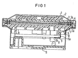
In der Figur 1 ist der bisherige Aufbau einer Sprechkapsel dargestellt. Mit 1 ist das Gehäuse bezeichnet, unter dessen Oberfläche ein Dämpfungsring 2 angeordnet ist. Unter den Dämpfungsring liegt eine Trennplatte 3. Der Wandler besteht aus einer Wandlerplatte 4 aus elektrisch leitenden Material und einer scheibenförmigen Piezokeramik, welche beidseitig und ganzflächig mit Elektroden versehen ist. Die mit den Elektroden versehene Piezokeramik ist mit der Wandlerplatte 4 durch Kleben fest verbunden. Der Wandler ist mit Hilfe von zwei Silikonringen 5a und 5b gehalten. Das druckkontaktierte Anschlußbändchen ist in der gezeichneten Schnittebene nicht dargestellt. Das aufgelötete Anschlußbändchen 6 wird zwischen Wandlerplatte 4 und Silikonring 5 zwischen einem Träger 7 aus Kunststoff und den Gehäuse aus Metall zur Bauteilseite 8 einer Verstärkerbaugruppe 9 geführt und dort an Griplet-Lötniete 8 angelötet. Mit 10 ist ein Kunststoffring bezeichnet, der die beiden Anschlußbändchen gegen das Metallgehäuse des Piezoaikrofons kurzschlußfest absichert. Im unteren Bereich des Gehäuses ist ein Isolierstoffkörper 11 vorgesehen.The previous structure of a speech capsule is shown in FIG. 1 with the housing is designated, under the surface of which a damping ring 2 is arranged. A separating
Der Erfindung liegt die Aufgabe zugrunde, den eingangs definierten und in Figur 1 dargestellten piezoelektrisch-akustischen Wandler derart zu verbessern, daß ein vollautomatisches Anlöten der beiden Anschlußbändchen der akustisch-elektrischen Wandlerplatte an die Verstärkerbaugruppe des Mikrofons ermöglicht wird. Ferner sind die AnschluBbändchen mit einen Etikett 10a anstelle des Kunststoffringes kurzschlußsicher gegen das Metallgehäuse zu isolieren.The object of the invention is to improve the piezoelectric-acoustic transducer defined at the outset and shown in FIG. 1 in such a way that fully automatic soldering of the two connection tapes of the acoustic-electric transducer plate to the amplifier module of the microphone is made possible. Furthermore, the connection tapes are to be insulated against the metal housing with a
Diese Aufgabe wird - wie in Figur 2 dargestellt - dadurch gelöst, daß die nicht mit der Wandlerplatte verbundenen Enden dieser Anschlußbändchen auf Leiterbahnen einer Verstärkerflachbaugruppe angelötet sind. Damit wird erreicht, daß die bisher benötigten teueren Griplet-Lötnieten und der für die Fixierung der Anschlußbändchen notwendige Silikonkleber entfallen können. Die Zugabe von Lötzinn und Flußmittel während des Lötvorganges ist ebenfalls nicht mehr notwendig, da das während des Schwallvorganges aufgebrachte Zinn und die Flußmittelreste für den Lötvorgang ausreichen.This task is - as shown in Figure 2 - solved in that the ends of these connecting tapes not connected to the converter plate are soldered onto conductor tracks of a flat amplifier module. This ensures that the previously expensive Griplet solder rivets and the silicone glue necessary for fixing the connecting tapes can be omitted. The addition of solder and flux during the soldering process is also no longer necessary, since the tin applied during the surge process and the flux residues are sufficient for the soldering process.
Nach einer Weiterbildung der Erfindung lassen die Anschlußstellen für die Bändchen einen Toleranzbereich für das Anlöten zu.According to a development of the invention, the connection points for the tapes allow a tolerance range for the soldering.
Voraussetzung für diese Art der automatengerechten Lötung der Anschlußbändchen ist eine erfindungsgemäß geänderte Montagefolge, die nur mit Hilfe eines Werkstückträgers bzw. mit einer entsprechenden Werkstückaufnahme möglich ist. Vorrichtungen dieser Art sind Gegenstand der Unteransprüche 3 bis 9. Die Trennplatte wird hierbei so in dem notwendigen Werkstückträger fixiert, daß die Leiterbahnseite frei zugänglich ist. Silikonringe und Wandlerplatte werden ebenfalls auf dem Werkstückträger vormontiert. Die beiden Anschlußbändchen kreuzen hierbei die Leiterbahn, an der die Bändchen angelötet werden. Mit Hilfe von zwei temperaturgeregelten Bügellöteinrichtungen werden die Bändchen in einem Reflow-Lötvorgang angelötet. Anschließend wird der Träger von oben auf die Verstärkerbaugruppe aufgedrückt. Verstärkerbaugruppe und Träger werden geschwenkt und in die Trennplatte eingedrückt.A prerequisite for this type of automatic soldering of the connection tapes is an assembly sequence modified according to the invention, which is only possible with the aid of a workpiece carrier or with a corresponding workpiece holder. Devices of this type are the subject of
In einem weiteren Arbeitsvorgang werden dann erfindungsgemäß die beiden Anschlußbändchen durch ein automatisch aufgebrachtes Etikett gegen das Metallgehäuse des Piezomikrofons kurzschlußfest abgesichert.In a further operation, the two connection tapes are then protected against short-circuit protection by an automatically applied label against the metal housing of the piezo microphone.
Die Erfindung wird anhand der Figuren 2 bis 7 erläutert. Es zeigen:
- Figur 1 ein bekanntes Piezo-Transistormikrofon im Schnitte
- Figur 2 die Leiterbahnseite der Verstärkerflachbaugruppe,
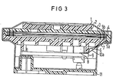
Figur 3 den Querschnitt einer Transistormikrofonkapsel mit auf der Leiterbahn angelöteten Anschlußbändchen und Isolieretikett,- Figur 4 einen Werkstückträger zur Aufnahme der Einheit konstruktive Halteelemente und Wandlerplatte sowie Verstärkerflachbaugruppe,
- Figur 5 die Vorrichtung nach Figur 4 zusätzlich mit Aushebevorrichtung und Reflowlötkopf,
Figur 6 in Ergänzung zu Figur 4 eine Trägerzuführeinrichtung und -Trägermontagestempel und- Figur 7 das teilmontierte Transistormikrofon nach einem Schwenk- und Montagevorgang durch eine nicht dargestellte Zusatzvorrichtung.
- Figure 1 shows a known piezo transistor microphone in sections
- FIG. 2 the conductor track side of the amplifier flat module,
- FIG. 3 shows the cross section of a transistor microphone capsule with connection strips and insulation label soldered onto the conductor track,
- FIG. 4 shows a workpiece carrier for holding the structural holding elements and transducer plate as well as a flat amplifier module,
- FIG. 5 the device according to FIG. 4 additionally with lifting device and reflow soldering head,
- Figure 6 in addition to Figure 4, a carrier feed device and carrier assembly stamp and
- Figure 7 shows the partially assembled transistor microphone after a swivel and assembly process by an additional device, not shown.
In der Figur 1 ist - wie bereits ausgeführt - ein Transistormikrofon im Schnitt gezeigt, bei dem die Anschlußbändchen über Griplet-Lötnieten 8 an der Flachbaugruppe 9 kontaktiert sind.In FIG. 1, as already explained, a transistor microphone is shown in section, in which the connection tapes are contacted on the flat module 9 via Griplet solder rivets 8.
Im linken Teil der Figur 2 sind die Leiterbahnen 12 zu erkennen, auf die die Anschlußbändchen in einem gewissen Toleranzbereich aufgelötet werden können.In the left part of FIG. 2, the
Die Figur 3 unterscheidet sich von der Figur 1 durch Wegfall der Griplet-Lötnieten 8 und die Kontaktierung der Bändchen auf die Leiterbahnen 12. Außerdem ist das Klebeetikett 10 zur Isolierung der Bändchen gegenüber dem Metallgehäuse dargestellt.FIG. 3 differs from FIG. 1 in that the Griplet solder rivets 8 are omitted and the strips are contacted on the
In der Figur 4 ist schematisch die Vormontage angedeutet. Ein Werkstückträger 13 umfaßt die Einheit der konstruktiven Halteelemente, die Trennplatte 3, die Silikonringe 5a und 5b und die Wandlerplatte 4 mit Anschlußbändchen 6. Der rechte Teil des Werkstückträgers ist für die Aufnahme der Verstärkerflachbaugruppe 9 ausgebildet.The preassembly is indicated schematically in FIG. A
Gegenüber der Figur 4 zeigt die Figur 5 zusätzlich eine Aushebevorrichtung 14 zum Ausheben der Verstärkerbaugruppe in die Lötposition. Ferner ist ein Reflowlötkopf 15 angedeutet.Compared to FIG. 4, FIG. 5 additionally shows a
Gegenüber der Darstellung in Figur 4 zeigt die Figur 6 zusätzlich den Trägerzuführ- und Montagestempel 16 in abgehobener Position, nachdem der Träger aufgesetzt wurde.Compared to the illustration in FIG. 4, FIG. 6 additionally shows the carrier feed and
In der Figur 7 ist schematisch eine Zusatzvorrichtung 17 angedeutet, die den Träger mit Verstärkerflachbaugruppe in Pfeilrichtung verschwenkt und in die Einheit der konstruktiven Halteelemente-und Wandlerplatte montiert.An additional device 17 is indicated schematically in FIG. 7, which pivots the carrier with the amplifier flat module in the direction of the arrow and mounts it in the unit of the structural holding element and transducer plate.
Der Montagevorgang läuft zum Beispiel folgendermaßen ab:
- In einer Station einer Transferstraße wird der.
Werkstückträger 13 mit der Einheit der konstruktiven Halteelemente und der Verstärkerbaugruppe bestückt (Figur 4). Dieser Vorgang kann automatisch erfolgen. In einer weiteren Transferstation, der Lötstation (Figur 5), wird die Verstärkerflächbaugruppe durch eine Zusatzeinrichtung in die Lötposition ausgehoben, um damit die für die spätere Montage notwendige Bändchenlage zu erhalten, der Reflowlötkopf 15 auf die Lötstelle abgesenkt und die Lötung der Anschlußbändchen auf den Leiterbahnen zeit- und temperaturgesteuert automatisch ausgeführt. Danach wird die Verstärkerflachbaugruppe wieder in den Werkstückträger abgesenkt.
- In a station on a transfer road the.
Workpiece carrier 13 equipped with the unit of the structural holding elements and the amplifier assembly (Figure 4). This can be done automatically. In a further transfer station, the soldering station (FIG. 5), the amplifier surface assembly is lifted into the soldering position by an additional device in order to obtain the ribbon position necessary for later assembly, the reflow soldering head 15 is lowered to the soldering point and the soldering of the connection tapes on the conductor tracks Executed automatically based on time and temperature. The amplifier flat module is then lowered back into the workpiece carrier.
Nach einem weiteren Transport in eine neue Transferstation (Figur 7) wird dort die Einheit Träger mit Verstärkerflachbaugruppe mit Hilfe einer zusätzlichen Vorrichtung geschwenkt und in die Einheit konstruktive Halteelemente und Wandlerplatte montiert.After a further transport to a new transfer station (FIG. 7), the unit carrier with amplifier flat module is pivoted there with the aid of an additional device and structural holding elements and converter plate are mounted in the unit.
Den Abschluß bildet in einer weiteren, nicht dargestellten Station das automatische Aufkleben des Etiketts 10a zur Bändchenisolierung.The conclusion in another station, not shown, is the automatic sticking on of the
9 Patentansprüche 7 Figuren9 claims 7 figures
Claims (9)
Priority Applications (1)
| Application Number | Priority Date | Filing Date | Title |
|---|---|---|---|
| AT85103709T ATE28715T1 (en) | 1984-04-11 | 1985-03-27 | PIEZOELECTRIC-ACOUSTIC TRANSDUCER FOR ELECTROACOUSTIC CAPSULES WITH CONSTRUCTION VERSION FOR MOUNTING. |
Applications Claiming Priority (2)
| Application Number | Priority Date | Filing Date | Title |
|---|---|---|---|
| DE3413697 | 1984-04-11 | ||
| DE3413697 | 1984-04-11 |
Publications (2)
| Publication Number | Publication Date |
|---|---|
| EP0158230A1 true EP0158230A1 (en) | 1985-10-16 |
| EP0158230B1 EP0158230B1 (en) | 1987-07-29 |
Family
ID=6233308
Family Applications (1)
| Application Number | Title | Priority Date | Filing Date |
|---|---|---|---|
| EP85103709A Expired EP0158230B1 (en) | 1984-04-11 | 1985-03-27 | Piezoelectric-acoustic transducer for electroacoustic units with constructional features for assembling |
Country Status (8)
| Country | Link |
|---|---|
| US (1) | US4674161A (en) |
| EP (1) | EP0158230B1 (en) |
| JP (1) | JPS60236599A (en) |
| AT (1) | ATE28715T1 (en) |
| AU (1) | AU573809B2 (en) |
| BR (1) | BR8501679A (en) |
| DE (1) | DE3560409D1 (en) |
| FI (1) | FI80366C (en) |
Families Citing this family (5)
| Publication number | Priority date | Publication date | Assignee | Title |
|---|---|---|---|---|
| EP0158230B1 (en) * | 1984-04-11 | 1987-07-29 | Siemens Aktiengesellschaft | Piezoelectric-acoustic transducer for electroacoustic units with constructional features for assembling |
| JP3992840B2 (en) * | 1998-06-22 | 2007-10-17 | 北陸電気工業株式会社 | Piezoelectric sounder and manufacturing method thereof |
| US6319054B1 (en) * | 2000-11-30 | 2001-11-20 | Avx Corporation | Electrical connector |
| US8249266B2 (en) * | 2004-05-17 | 2012-08-21 | Sperian Hearing Protection, Llc | Filter system for hearing protection device for continuous noise exposure monitoring |
| US7978861B2 (en) * | 2004-05-17 | 2011-07-12 | Sperian Hearing Protection, Llc | Method and apparatus for continuous noise exposure monitoring |
Citations (4)
| Publication number | Priority date | Publication date | Assignee | Title |
|---|---|---|---|---|
| US3500013A (en) * | 1966-07-07 | 1970-03-10 | Philips Corp | Method of making connections to a microcircuit |
| LU67103A1 (en) * | 1972-02-29 | 1973-05-03 | ||
| EP0007436A1 (en) * | 1978-07-17 | 1980-02-06 | Siemens Aktiengesellschaft | Electro-acoustic transducer with a membrane having a piezoelectric layer |
| FR2530108A1 (en) * | 1982-07-12 | 1984-01-13 | Geophysique Cie Gle | Novel hydrophone |
Family Cites Families (6)
| Publication number | Priority date | Publication date | Assignee | Title |
|---|---|---|---|---|
| US3331970A (en) * | 1964-09-29 | 1967-07-18 | Honeywell Inc | Sonic transducer |
| US3879726A (en) * | 1972-03-20 | 1975-04-22 | Mallory & Co Inc P R | Audible alarm unit |
| DE2858153C2 (en) * | 1978-05-10 | 1984-10-18 | Siemens AG, 1000 Berlin und 8000 München | Method for gluing an electrical component with a sheet-like electrode to a carrier plate |
| US4190784A (en) * | 1978-07-25 | 1980-02-26 | The Stoneleigh Trust, Fred M. Dellorfano, Jr. & Donald P. Massa, Trustees | Piezoelectric electroacoustic transducers of the bi-laminar flexural vibrating type |
| DE3007834A1 (en) * | 1980-02-29 | 1981-09-17 | Siemens AG, 1000 Berlin und 8000 München | ELECTROACOUSTIC CONVERTER |
| EP0158230B1 (en) * | 1984-04-11 | 1987-07-29 | Siemens Aktiengesellschaft | Piezoelectric-acoustic transducer for electroacoustic units with constructional features for assembling |
-
1985
- 1985-03-27 EP EP85103709A patent/EP0158230B1/en not_active Expired
- 1985-03-27 AT AT85103709T patent/ATE28715T1/en not_active IP Right Cessation
- 1985-03-27 DE DE8585103709T patent/DE3560409D1/en not_active Expired
- 1985-04-03 US US06/719,467 patent/US4674161A/en not_active Expired - Fee Related
- 1985-04-10 AU AU40981/85A patent/AU573809B2/en not_active Ceased
- 1985-04-10 BR BR8501679A patent/BR8501679A/en not_active IP Right Cessation
- 1985-04-10 JP JP60076317A patent/JPS60236599A/en active Granted
- 1985-04-10 FI FI851418A patent/FI80366C/en not_active IP Right Cessation
Patent Citations (4)
| Publication number | Priority date | Publication date | Assignee | Title |
|---|---|---|---|---|
| US3500013A (en) * | 1966-07-07 | 1970-03-10 | Philips Corp | Method of making connections to a microcircuit |
| LU67103A1 (en) * | 1972-02-29 | 1973-05-03 | ||
| EP0007436A1 (en) * | 1978-07-17 | 1980-02-06 | Siemens Aktiengesellschaft | Electro-acoustic transducer with a membrane having a piezoelectric layer |
| FR2530108A1 (en) * | 1982-07-12 | 1984-01-13 | Geophysique Cie Gle | Novel hydrophone |
Also Published As
| Publication number | Publication date |
|---|---|
| US4674161A (en) | 1987-06-23 |
| JPS60236599A (en) | 1985-11-25 |
| AU4098185A (en) | 1985-10-17 |
| FI80366C (en) | 1990-05-10 |
| FI851418L (en) | 1985-10-12 |
| EP0158230B1 (en) | 1987-07-29 |
| BR8501679A (en) | 1985-12-10 |
| ATE28715T1 (en) | 1987-08-15 |
| JPH0460400B2 (en) | 1992-09-25 |
| FI851418A0 (en) | 1985-04-10 |
| AU573809B2 (en) | 1988-06-23 |
| FI80366B (en) | 1990-01-31 |
| DE3560409D1 (en) | 1987-09-03 |
Similar Documents
| Publication | Publication Date | Title |
|---|---|---|
| DE19719492C2 (en) | Vibrator device | |
| DE3125518C2 (en) | Method of making a thin wiring assembly - US Pat | |
| DE2345149A1 (en) | ELECTRONIC HYBRID COMPONENT WITH SEMI-CONDUCTOR CHIPS | |
| EP0762817A1 (en) | Shielding for flat assemblies | |
| EP0069824A1 (en) | Method of making contact with the adhesive side of an electrode of an electric device | |
| DE3104623A1 (en) | METHOD FOR FASTENING COMPONENTS WITH FLAT CONNECTORS AND COMPONENT HERE | |
| EP0140126A1 (en) | Method of tape-automated bonding | |
| EP0162149A1 (en) | Electrical capacitor as a chip element | |
| DE2810054A1 (en) | ELECTRONIC CIRCUIT DEVICE AND METHOD OF MANUFACTURING IT | |
| EP0112559A1 (en) | Loudspeaker | |
| EP1817803A1 (en) | Contacting multilayer piezo actuators or sensors | |
| EP0158230B1 (en) | Piezoelectric-acoustic transducer for electroacoustic units with constructional features for assembling | |
| DE4121449A1 (en) | HOER DEVICE, IN PARTICULAR WEARING MINI HEAT DEVICE, AND METHOD FOR THE PRODUCTION THEREOF | |
| DE10158529B4 (en) | temperature sensor | |
| EP0708578A2 (en) | Connection line | |
| EP1480291B1 (en) | Electronic assembly | |
| DE2546443C3 (en) | Composite microcircuit and process for its manufacture | |
| DE102013202232B4 (en) | Circuit board with heat-resistant lead wire and method for the manufacture thereof | |
| WO1997008925A1 (en) | Method of establishing a connection between at least two electrical conductors, one of which is mounted on a supporting substrate | |
| EP0702378B1 (en) | Chip inductor | |
| EP0061648A2 (en) | Electrical device the active part of which is placed on a metal support, and process for the manufacture of the device | |
| DE7831808U1 (en) | SMALL HEATER | |
| KR850000166B1 (en) | Method production for printed circuit board | |
| DE8435052U1 (en) | CONVERTER PLATE FOR PIEZOELECTRIC CONVERTER | |
| DE3346461A1 (en) | Method for manufacturing a telephone station |
Legal Events
| Date | Code | Title | Description |
|---|---|---|---|
| PUAI | Public reference made under article 153(3) epc to a published international application that has entered the european phase |
Free format text: ORIGINAL CODE: 0009012 |
|
| AK | Designated contracting states |
Designated state(s): AT BE CH DE FR GB IT LI LU NL SE |
|
| 17P | Request for examination filed |
Effective date: 19850827 |
|
| 17Q | First examination report despatched |
Effective date: 19860930 |
|
| GRAA | (expected) grant |
Free format text: ORIGINAL CODE: 0009210 |
|
| AK | Designated contracting states |
Kind code of ref document: B1 Designated state(s): AT BE CH DE FR GB IT LI LU NL SE |
|
| REF | Corresponds to: |
Ref document number: 28715 Country of ref document: AT Date of ref document: 19870815 Kind code of ref document: T |
|
| REF | Corresponds to: |
Ref document number: 3560409 Country of ref document: DE Date of ref document: 19870903 |
|
| ET | Fr: translation filed | ||
| ITF | It: translation for a ep patent filed |
Owner name: STUDIO JAUMANN |
|
| PLBE | No opposition filed within time limit |
Free format text: ORIGINAL CODE: 0009261 |
|
| STAA | Information on the status of an ep patent application or granted ep patent |
Free format text: STATUS: NO OPPOSITION FILED WITHIN TIME LIMIT |
|
| 26N | No opposition filed | ||
| ITTA | It: last paid annual fee | ||
| PGFP | Annual fee paid to national office [announced via postgrant information from national office to epo] |
Ref country code: LU Payment date: 19920318 Year of fee payment: 8 Ref country code: BE Payment date: 19920318 Year of fee payment: 8 |
|
| PGFP | Annual fee paid to national office [announced via postgrant information from national office to epo] |
Ref country code: FR Payment date: 19920323 Year of fee payment: 8 |
|
| PGFP | Annual fee paid to national office [announced via postgrant information from national office to epo] |
Ref country code: SE Payment date: 19920324 Year of fee payment: 8 |
|
| PGFP | Annual fee paid to national office [announced via postgrant information from national office to epo] |
Ref country code: CH Payment date: 19920622 Year of fee payment: 8 |
|
| EPTA | Lu: last paid annual fee | ||
| PGFP | Annual fee paid to national office [announced via postgrant information from national office to epo] |
Ref country code: GB Payment date: 19930216 Year of fee payment: 9 |
|
| PGFP | Annual fee paid to national office [announced via postgrant information from national office to epo] |
Ref country code: AT Payment date: 19930224 Year of fee payment: 9 |
|
| PG25 | Lapsed in a contracting state [announced via postgrant information from national office to epo] |
Ref country code: LU Free format text: LAPSE BECAUSE OF NON-PAYMENT OF DUE FEES Effective date: 19930327 |
|
| PG25 | Lapsed in a contracting state [announced via postgrant information from national office to epo] |
Ref country code: SE Effective date: 19930328 |
|
| PG25 | Lapsed in a contracting state [announced via postgrant information from national office to epo] |
Ref country code: LI Effective date: 19930331 Ref country code: CH Effective date: 19930331 Ref country code: BE Effective date: 19930331 |
|
| PGFP | Annual fee paid to national office [announced via postgrant information from national office to epo] |
Ref country code: NL Payment date: 19930331 Year of fee payment: 9 |
|
| PGFP | Annual fee paid to national office [announced via postgrant information from national office to epo] |
Ref country code: DE Payment date: 19930518 Year of fee payment: 9 |
|
| BERE | Be: lapsed |
Owner name: SIEMENS A.G. BERLIN UND MUNCHEN Effective date: 19930331 |
|
| PG25 | Lapsed in a contracting state [announced via postgrant information from national office to epo] |
Ref country code: FR Effective date: 19931130 |
|
| REG | Reference to a national code |
Ref country code: CH Ref legal event code: PL |
|
| REG | Reference to a national code |
Ref country code: FR Ref legal event code: ST |
|
| PG25 | Lapsed in a contracting state [announced via postgrant information from national office to epo] |
Ref country code: GB Effective date: 19940327 Ref country code: AT Effective date: 19940327 |
|
| PG25 | Lapsed in a contracting state [announced via postgrant information from national office to epo] |
Ref country code: NL Effective date: 19941001 |
|
| NLV4 | Nl: lapsed or anulled due to non-payment of the annual fee | ||
| GBPC | Gb: european patent ceased through non-payment of renewal fee |
Effective date: 19940327 |
|
| PG25 | Lapsed in a contracting state [announced via postgrant information from national office to epo] |
Ref country code: DE Effective date: 19941201 |
|
| EUG | Se: european patent has lapsed |
Ref document number: 85103709.3 Effective date: 19931008 |