EP0158228B1 - Inductive radio control system for vehicles - Google Patents
Inductive radio control system for vehicles Download PDFInfo
- Publication number
- EP0158228B1 EP0158228B1 EP85103683A EP85103683A EP0158228B1 EP 0158228 B1 EP0158228 B1 EP 0158228B1 EP 85103683 A EP85103683 A EP 85103683A EP 85103683 A EP85103683 A EP 85103683A EP 0158228 B1 EP0158228 B1 EP 0158228B1
- Authority
- EP
- European Patent Office
- Prior art keywords
- travelling
- transmitting
- signal
- vehicle
- unit
- Prior art date
- Legal status (The legal status is an assumption and is not a legal conclusion. Google has not performed a legal analysis and makes no representation as to the accuracy of the status listed.)
- Expired
Links
- 230000001939 inductive effect Effects 0.000 title claims description 30
- 230000005540 biological transmission Effects 0.000 claims description 29
- 230000008878 coupling Effects 0.000 claims description 7
- 238000010168 coupling process Methods 0.000 claims description 7
- 238000005859 coupling reaction Methods 0.000 claims description 7
- 238000004891 communication Methods 0.000 claims description 5
- 238000010586 diagram Methods 0.000 description 13
- 238000001514 detection method Methods 0.000 description 10
- 238000000034 method Methods 0.000 description 3
- 101000661807 Homo sapiens Suppressor of tumorigenicity 14 protein Proteins 0.000 description 2
- 101000760620 Homo sapiens Cell adhesion molecule 1 Proteins 0.000 description 1
- 101000911772 Homo sapiens Hsc70-interacting protein Proteins 0.000 description 1
- 101001139126 Homo sapiens Krueppel-like factor 6 Proteins 0.000 description 1
- 101000710013 Homo sapiens Reversion-inducing cysteine-rich protein with Kazal motifs Proteins 0.000 description 1
- 101000661816 Homo sapiens Suppression of tumorigenicity 18 protein Proteins 0.000 description 1
- 230000000593 degrading effect Effects 0.000 description 1
- 238000009434 installation Methods 0.000 description 1
- 108090000237 interleukin-24 Proteins 0.000 description 1
Images



Classifications
-
- B—PERFORMING OPERATIONS; TRANSPORTING
- B61—RAILWAYS
- B61L—GUIDING RAILWAY TRAFFIC; ENSURING THE SAFETY OF RAILWAY TRAFFIC
- B61L3/00—Devices along the route for controlling devices on the vehicle or train, e.g. to release brake or to operate a warning signal
- B61L3/02—Devices along the route for controlling devices on the vehicle or train, e.g. to release brake or to operate a warning signal at selected places along the route, e.g. intermittent control simultaneous mechanical and electrical control
- B61L3/08—Devices along the route for controlling devices on the vehicle or train, e.g. to release brake or to operate a warning signal at selected places along the route, e.g. intermittent control simultaneous mechanical and electrical control controlling electrically
- B61L3/12—Devices along the route for controlling devices on the vehicle or train, e.g. to release brake or to operate a warning signal at selected places along the route, e.g. intermittent control simultaneous mechanical and electrical control controlling electrically using magnetic or electrostatic induction; using radio waves
- B61L3/121—Devices along the route for controlling devices on the vehicle or train, e.g. to release brake or to operate a warning signal at selected places along the route, e.g. intermittent control simultaneous mechanical and electrical control controlling electrically using magnetic or electrostatic induction; using radio waves using magnetic induction
-
- B—PERFORMING OPERATIONS; TRANSPORTING
- B61—RAILWAYS
- B61L—GUIDING RAILWAY TRAFFIC; ENSURING THE SAFETY OF RAILWAY TRAFFIC
- B61L27/00—Central railway traffic control systems; Trackside control; Communication systems specially adapted therefor
- B61L27/70—Details of trackside communication
-
- B—PERFORMING OPERATIONS; TRANSPORTING
- B61—RAILWAYS
- B61L—GUIDING RAILWAY TRAFFIC; ENSURING THE SAFETY OF RAILWAY TRAFFIC
- B61L3/00—Devices along the route for controlling devices on the vehicle or train, e.g. to release brake or to operate a warning signal
- B61L3/16—Continuous control along the route
- B61L3/22—Continuous control along the route using magnetic or electrostatic induction; using electromagnetic radiation
Definitions
- the present invention relates to an inductive radio control system for controlling a plurality of unmanned vehicles driven by an inductive radio apparatus along a predetermined route.
- Unmanned vehicles are driven along predetermined routes in factories and the like to transport products. Current positions of vehicles are detected by a ground control unit, and the vehicles are controlled by a computer, a sequence controller or the like in accordance with the scheduled destinations thereof.
- a data transmission unit is connected between the ground control unit and each vehicle. Operation instruction data is supplied from the control unit to each vehicle, and vehicle data is sent back from each vehicle to the control unit.
- a conventional data transmission unit comprises an inductive radio apparatus.
- a inductive trolley is arranged along the entire path to continuously exchange data between the control unit and the vehicles.
- the inductive trolley must be divided at points of the path, railroad crossings or the like.
- a transmitter/receiver is required for each divided inductive trolley.
- a proper method of installing the inductive trolley and a switching unit for data exchange between the respective divided inductive trolleys must be provided.
- a plurality of loop antennas are separately arranged along the path and communication between the ground control unit and the vehicle is established every time when a vehicle passes a loop antenna.
- a stop instruction or a run instruction to a next loop antenna is supplied to the vehicle under a given loop antenna.
- transmitters/receivers of an inductive radio apparatus are provided for the respective loop antennas.
- numerous transmitters/receivers are required although the maximum number of actually operated units is the same as the number of vehicles, resulting in a high-cost, redundant system.
- this system when a failure occurs in a given transmitter/receiver, data transmission cannot be performed between the corresponding loop antenna and a passing vehicle so that the reliability of the system is degraded.
- a loop antenna for a faulty transmitter/receiver is located at a stop position of a vehicle, entire system-down of an unmanned operation system occurs.
- Prior art document FR-A-2 336 751 discloses an inductive radio control system for performing data transmission by inductive radio means between a vehicle which travels along a travel path formed in a predetermined route and a central controlling unit.
- the central controlling unit sends out a control signal which controls the vehicle and receives from the vehicle a signal which indicates its position and destination.
- Loop antennas are arranged along the travel path to provide with transmitting/receiving means the above explained signals in both directions.
- selecting means selectively couple one of the loop antennas with the vehicle so as to perform data transmission by the inductive radio means.
- a ground unit can be simplified and the number of transmitters/receivers is kept to a minimum, thereby providing an inductive radio control system with high reliability at low cost.
- data transmission is performed by the inductive radio apparatus between the transmitters/receivers and loop antennas separately arranged on the ground by using a signal obtained such that a single tone signal or a plurality of tone signals having frequencies of several handreds are FM-modulated on a carrier wave having a frequency of about 100 kHz.
- Instruction signals representing the travel direction, stoppage, braking, speed and the like of a vehicle are supplied from the ground unit to the vehicles through the loop antennas.
- Status signals representing the travel direction, speed, braking, motor operation and the like are transmitted from the vehicles to the ground unit.
- Each vehicle has a floating battery powered from a power trolley, a motor driven by the floating battery, a brake mechanism and the like. Each vehicle can be driven for a short distance by only the battery power without being powered from the power trolley.
- a travel path 1 is provided for an entire route, and a plurality of vehicles 2 are driven along the path 1.
- Points 3 are properly installed along the path 1.
- Point control units 4 are coupled to the points 3.
- the point control unit 4 is activated by an operation control unit 5 through a point control system (not shown) in accordance with the operation schedule of the vehicles.
- Road crossings 6 are properly provided along the path 1 and crossing control units 7 are arranged in the crossings 6.
- the crossing control units 7 are controlled by the unit 5 through a crossing control system (not shown) in accordance with the operation schedule of the vehicles.
- Ground loop antennas 8-1 to 8-n are separately arranged along the path 1 to exchange data between the unit 5 and the vehicles 2.
- the antennas 8-1 to 8-n are arranged at the entrances of block section, at the points 3 which are important for safety, at positions before and after the crossings 6, and at stop positions (i.e., work areas) of the vehicles 2.
- Each of the antennas 8-1 to 8-n has such a length that data can be exchanged between the vehicle 2 and the unit 5 even if the vehicle 2 enters the block section at the highest possible speed. Alternatively, it has a length which is the sum of the distance that the vehicle 2 runs until it stops after it has received a stop instruction and the distance that the vehicle 2 need to receive a restart instruction and to send a normal running condition after it has stopped and the estimated extra distance.
- the antennas 8-1 to 8-n communicate with the unit 5 through antenna cables 9 and a ground unit 10.
- the unit 5 controls the entire system in accordance with data (e.g., operation schedule) supplied from a master computer 11 designed for production control.
- a work schedule instruction is normally supplied from the computer 11 to the unit 5.
- the unit 5 controls the operation of the vehicles 2 in accordance with the work schedule.
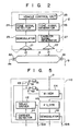
- Fig. 2 is a block diagram showing the arrangement of the trolley 2.
- the loop antenna 8 arranged along the path 1 is connected to the unit 10 through the corresponding cable 9.
- a line coupler 81 and a terminating resistor 82 are connected to the edns of the antenna 8, respectively.
- a vehicle receiving antenna 21 and a vehicle transmission antenna 22 are mounted on the vehicle to face the loop antenna 8.
- the carrier wave component of a signal induced by the antenna 21 is removed by a demodulator 23, so that only the modulated wave component is demodulated.
- the demodulated wave component is supplied to a tone signal detector 24 which detects the contents of the tone signal.
- a detection result is supplied to a vehicle control unit 25.
- a switch or the like is controlled in accordance with the content of the tone signal, and the operation of the vehicle is controlled.
- the operation states of the motor and the brake mechanism and the vehicle speed are detected by proper sensors. Outputs from these sensors are supplied to the unit 25.
- the unit 25 supplies a selection signal to a tone signal generator 26 so as to select the tone signal represented by the detection state.
- the generator 26 generates a single tone signal or a plurality of tone signals having a frequency represented by the selection signal.
- the single tone signal or the plurality of tone signals are supplied to a carrier signal generator 27 to FM-modulate the carrier wave.
- the FM-modulated carrier wave is sent from the antenna 22 to the antenna 8.
- Fig. 3 is a block diagram showing the detailed arrangement of the ground unit 10.
- the antennas 8-1 to 8-n are connected to line coupling units 110-1 to 110-n through the cables 9, respectively.
- the number of line coupling units is the same as that of loop antennas.
- Input/output signals with respect to the units 110-1 to 110-n are coupled to transmitters/receivers 140-1 to 140-m through a transmission distributor 120 and a receiving distributor 130.
- the number of transmitters/receivers 140-1 to 140-m is the same as the maximum number of operating vehicles.
- Fig. 4 is a block diagram showing the transmitter/receiver 140.
- the transmitter/receiver 140 supplies a tone signal to a tone signal generator 141 in accordance with a vehicle control signal S11 generated by the unit 5.
- the tone signal is supplied to a carrier signal generator 142 and is modulated thereby.
- the modulated carrier wave is supplied to a transmission selector switch 144 through a filter 143.
- the tone signal supplied to a reception selector switch 145 is detected by a tone signal detector 146.
- a vehicle monitor signal S12 is supplied to the unit 5.
- the switches 144 and 145 are controlled by a loop selection signal S13 generated by the unit 5 and select the loop antenna 8 which sends out the signal S11 and receives the signal S12.
- the output from the switch 144 is sent out through the selected antenna 8 via the distributor 120.
- the signal received by the selected antenna 8 is supplied to the tone signal detector 146 through the distributor 130 and the switch 145.
- the vehicle 2 can communicate with one of the antennas 8-1 to 8-n only when the vehicle 2 is located above the corresponding loop antenna.
- the signal S11 received from the loop antenna behind the vehicle is stored in the unit 25 and the vehicle moves under the control of the stored signal S11.
- Fig. 5 is a block diagram of a line coupling unit 110.
- the output from the distributor 120 is supplied to a carrier detector 111.
- a detection signal from the detector 111 drives a switching relay 113 through a relay driver 112.
- the output from the distributor 120 is supplied to the corresponding antenna 8 through a mixer 114 and the cable 9 in accordance with the operating states of contacts S1 and S2 of the relay 113.
- a carrier wave detection signal S14 is generated from the driver 112 to indicate that data transmission is being performed.
- the signal received by the antenna 8 is supplied to a filter 115 through the cable 9 and the mixer 114 is demodulated by a demodulator 116.
- the demodulated signal is supplied to the transmitter/receiver 140 through the distributor 130.
- the demodulator 116 supplies the carrier wave detection signal S15 to the unit 5 during data reception.
- the inductive radio apparatus on the vehicle supplies the signal S12 to the ground system at all times.
- the signal S12 is supplied to the unit 5.
- the signal S12 is supplied from the unit 25 to the demodulator 116 through the generators 26 and 27, the antennas 22 and 8-1, the coupler 81, the mixer 114 and the filter 115 in the order mentioned.
- the signal S15 is supplied from the line coupling unit 110-1 to the unit 5.
- the unit 5 receives the signal S15 from the unit 110-1, the unit 5 detects that the vehicle 2 is located above the antenna 8-1 and selects one of the transmitters/receivers 140-1 to 140-m.
- the unit 5 continuously monitors the operations of the transmitters/receivers 140-1 to 140-m. When the unit 5 receives the signal S15 from the unit 110, the unit 5 supplies a loop selection signal S13 to any one of the transmitters/receivers not in use among the transmitters/receivers 140-1 to 140-m.
- the unit 5 supplies the signal S13 to the transmitter/receiver 140-2.
- the transmitter/receiver 140-2 is coupled to the unit 110-1 through the switches 144 and 145 of the transmitter/receiver 140-2 and the distributors 120 and 130.
- data can be exchanged between the vehicle 2 and the unit 5.
- the unit 5 selects response data (e.g., vehicle number) which the vehicle gives to the ground system in any case. This response data is selected from the signal S12.
- response data e.g., vehicle number
- This response data is selected from the signal S12.
- the reception system of the transmitter/receiver 140-2 is determined to be normal.
- Other data included in the signal S12 are also regarded as normal.
- the data necessary for vehicle control is supplied as the signal S11 from the unit 5 to the transmitter/receiver 140-2.
- the signal S11 generated from the ground system is supplied to the unit 110-1 through the switch 144 and the distributor 120.
- the carrier wave of the signal S11 is detected by the detector 111, and the relay 113 is energized to switch the contacts S1 and S2. Therefore, the signal S11 is transmitted from the ground system to the vehicle through the antenna 8-1.
- the contacts S1 and S2 are operated to establish communication between the vehicle and the ground system.
- the signal S13 from the unit 5 is disabled in order to disconnect the transmitter/receiver 140-2.
- One of the unoccupied transmitters/receivers among the transmitters/receivers 140-1 and 140-3 to 140-m is then selected.
- the transmission and reception systems of the selected transmitter/receiver are checked to determine whether or not a failure has occurred therein. If this transmitter/receiver is detected to be normal, communication between the vehicle and the ground system is established.
- the operating state signal of the relay 113 of each of the units 110-1 to 110-n is supplied to the unit 5.
- the unit 5 can check this state if it is needed.
- Figs. 6 to 8 are flow charts for explaining the operation of the unit 5.
- Fig. 6 is concerned with the routine of data transmission from the vehicle 2 to the unit 5.
- the unit 5 reads in or fetches a digital input.
- the unit 5 checks the status of the inductive radio apparatus.
- the unit 5 detects the carrier wave (S15).
- the unit 5 checks the sequence when the vehicle enters a loop antenna field. When the detection operations in ST2 to ST4 are determined to be normal, the corresponding loop antenna is coupled to an unused transmitter/receiver in accordance with the loop selected signal (S13) in ST5.
- the unit 5 fetches the digital input in ST6 and checks the vehicle monitor signal (S12) in ST7.
- the unit 5 checks the vehicle monitor data in ST8 and stores data such as the loop antenna number, and in ST9 the vehicle number and the operating state of the vehicle necessary for the trolley operation are stored.
- the transmitter/receiver now coupled to the loop antenna is registered as being used in ST10. The flow then returns to ST1.
- a failure processing routine is executed.
- Fig. 7 shows a routine for supplying a vehicle control command from the unit 5 to the vehicle.
- the unit 5 supplies the vehicle control signal (S11) to the vehicle in ST11 and a carrier transmission command to the vehicle in ST12.
- the unit 5 receives a digital input signal in ST13 and checks the carrier wave detection in ST14. When the carrier wave detection signal (S14) is not detected in ST14, another transmitter/receiver is accessed in ST15.
- the unit 5 checks the response to control data in ST16. The data necessary for the vehicle operation is then stored in ST17, and in ST18 the selected transmitter/receiver is registered and the flow returns to ST11.
- Fig. 8 shows the routine of transmitter/receiver processing when the vehicle 2 leaves the antenna 8.
- the carrier transmission command, the vehicle control signal (S11) and the loop selection signal (S13) of the loop antenna are disabled in ST21, ST22 and ST23, respectively.
- ST24 the registration of the in-use transmitter/receiver is cleared and the flow returns to ST21.
- Fig. 9 is a block diagram of an inductive radio control system according to another embodiment of the present invention.
- Emergency loop antennas 13-1 to 13-q are arranged in portions of the route where loop antennas are not provided.
- Carrier transmission units 14-1 to 14-q can generate carrier signals in response to a command from an operation control unit 5.
- the vehicle receives only the carrier wave which is not modulated with the tone signal, the contents of the control signal are cleared, the motor of the vehicle is stopped, and the brake mechanism is actuated to stop the vehicle.
- the vehicle 2 can be stopped in an emergency situation, thereby further guaranteeing safety.
Landscapes
- Engineering & Computer Science (AREA)
- Mechanical Engineering (AREA)
- Physics & Mathematics (AREA)
- Electromagnetism (AREA)
- Control Of Position, Course, Altitude, Or Attitude Of Moving Bodies (AREA)
Description
- The present invention relates to an inductive radio control system for controlling a plurality of unmanned vehicles driven by an inductive radio apparatus along a predetermined route.
- Unmanned vehicles are driven along predetermined routes in factories and the like to transport products. Current positions of vehicles are detected by a ground control unit, and the vehicles are controlled by a computer, a sequence controller or the like in accordance with the scheduled destinations thereof.
- A data transmission unit is connected between the ground control unit and each vehicle. Operation instruction data is supplied from the control unit to each vehicle, and vehicle data is sent back from each vehicle to the control unit.
- In this case, a conventional data transmission unit comprises an inductive radio apparatus. A inductive trolley is arranged along the entire path to continuously exchange data between the control unit and the vehicles. However, it is difficult to provide the inductive trolley at points of the path and intersections with other paths and on road crossing. For this reason, the inductive trolley must be divided at points of the path, railroad crossings or the like. When the inductive trolley is divided, a transmitter/receiver is required for each divided inductive trolley. In addition, in order to guarantee continuity of data exchange between the divided inductive trolleys, a proper method of installing the inductive trolley and a switching unit for data exchange between the respective divided inductive trolleys must be provided. When a vehicle path is complex, such a data transmission unit requires a complicated arrangement, resulting in high cost and impairing the reliability of the operation.
- In order to detect a current vehicle position in the conventional system described above, a separate position sensor is required, or a travel distance is calculated by the number of revolutions of the wheel from the start point so as to estimate the current vehicle position. However, with the former method, total installation cost is increased. With the latter method, the degree of error is increased with an increase in distance, thereby degrading the precision of detecting a current vechile position.
- In order to solve the above problems, a plurality of loop antennas are separately arranged along the path and communication between the ground control unit and the vehicle is established every time when a vehicle passes a loop antenna. A stop instruction or a run instruction to a next loop antenna is supplied to the vehicle under a given loop antenna. These instructions are stored on a vehicle to control the operation of the vehicle.
- In the data transmission unit described above, transmitters/receivers of an inductive radio apparatus are provided for the respective loop antennas. However, when the number of vehicles is small as compared with the number of loop antennas, numerous transmitters/receivers are required although the maximum number of actually operated units is the same as the number of vehicles, resulting in a high-cost, redundant system. In addition, in this system, when a failure occurs in a given transmitter/receiver, data transmission cannot be performed between the corresponding loop antenna and a passing vehicle so that the reliability of the system is degraded. Furthermore, when a loop antenna for a faulty transmitter/receiver is located at a stop position of a vehicle, entire system-down of an unmanned operation system occurs.
- Prior art document FR-A-2 336 751 discloses an inductive radio control system for performing data transmission by inductive radio means between a vehicle which travels along a travel path formed in a predetermined route and a central controlling unit. The central controlling unit sends out a control signal which controls the vehicle and receives from the vehicle a signal which indicates its position and destination. Loop antennas are arranged along the travel path to provide with transmitting/receiving means the above explained signals in both directions. Finally selecting means selectively couple one of the loop antennas with the vehicle so as to perform data transmission by the inductive radio means.
- It is an object of the present invention to provide a simple inductive radio control system with a simple system configuration and high reliability of low cost.
- In order to achieve the above object of the present invention, there is provided an inductive radio control system as stated in
claim 1. - According to the present invention, a ground unit can be simplified and the number of transmitters/receivers is kept to a minimum, thereby providing an inductive radio control system with high reliability at low cost.
- This invention can be more fully understood from the following detailed description when taken in conjunction with the accompanying drawings, in which:
- Fig. 1 is a block diagram of an inductive radio control system according to an embodiment of the present invention;
- Fig. 2 is a block diagram showing the arrangement of a vehicle shown in Fig. 1;
- Fig. 3 is a block diagram showing the arrangement of a ground unit shown in Fig. 1;
- Fig. 4 is a block diagram showing the arrangement of a transmitter/receiver shown in Fig. 3;
- Fig. 5 is a block diagram showing the arrangement of a line coupling unit shown in Fig. 3;
- Figs. 6 to 8 are flow charts for explaining the operation of the operation control unit shown in Fig. 1; and
- Fig. 9 is a block diagram of an inductive radio control system device according to another embodiment of the present invention.
- An inductive radio control system according to an embodiment of the present invention will be described with reference to the block diagram of Fig. 1 which illustrates the overall system configuration and the block diagrams of Figs. 2 to 5 which illustrate the detailed arrangements of the respective components.
- In this system, data transmission is performed by the inductive radio apparatus between the transmitters/receivers and loop antennas separately arranged on the ground by using a signal obtained such that a single tone signal or a plurality of tone signals having frequencies of several handreds are FM-modulated on a carrier wave having a frequency of about 100 kHz. Instruction signals representing the travel direction, stoppage, braking, speed and the like of a vehicle are supplied from the ground unit to the vehicles through the loop antennas. Status signals representing the travel direction, speed, braking, motor operation and the like are transmitted from the vehicles to the ground unit.
- Each vehicle has a floating battery powered from a power trolley, a motor driven by the floating battery, a brake mechanism and the like. Each vehicle can be driven for a short distance by only the battery power without being powered from the power trolley.
- Referring to Fig. 1, a
travel path 1 is provided for an entire route, and a plurality ofvehicles 2 are driven along thepath 1.Points 3 are properly installed along thepath 1. Point control units 4 are coupled to thepoints 3. The point control unit 4 is activated by anoperation control unit 5 through a point control system (not shown) in accordance with the operation schedule of the vehicles.Road crossings 6 are properly provided along thepath 1 and crossingcontrol units 7 are arranged in thecrossings 6. Thecrossing control units 7 are controlled by theunit 5 through a crossing control system (not shown) in accordance with the operation schedule of the vehicles. - Ground loop antennas 8-1 to 8-n are separately arranged along the
path 1 to exchange data between theunit 5 and thevehicles 2. With consideration for the operation schedule of the vehicles, the antennas 8-1 to 8-n are arranged at the entrances of block section, at thepoints 3 which are important for safety, at positions before and after thecrossings 6, and at stop positions (i.e., work areas) of thevehicles 2. Each of the antennas 8-1 to 8-n has such a length that data can be exchanged between thevehicle 2 and theunit 5 even if thevehicle 2 enters the block section at the highest possible speed. Alternatively, it has a length which is the sum of the distance that thevehicle 2 runs until it stops after it has received a stop instruction and the distance that thevehicle 2 need to receive a restart instruction and to send a normal running condition after it has stopped and the estimated extra distance. - The antennas 8-1 to 8-n communicate with the
unit 5 throughantenna cables 9 and aground unit 10. Theunit 5 controls the entire system in accordance with data (e.g., operation schedule) supplied from a master computer 11 designed for production control. - A work schedule instruction is normally supplied from the computer 11 to the
unit 5. Theunit 5 controls the operation of thevehicles 2 in accordance with the work schedule. - When the computer 11 is off-lined from the
unit 5, the on-line operation is interrupted, or when an interrupt schedule is generated, schedule data is supplied from ascheduling unit 12 to thecontrol unit 5. - Fig. 2 is a block diagram showing the arrangement of the
trolley 2. Theloop antenna 8 arranged along thepath 1 is connected to theunit 10 through thecorresponding cable 9. Aline coupler 81 and a terminatingresistor 82 are connected to the edns of theantenna 8, respectively. - A
vehicle receiving antenna 21 and avehicle transmission antenna 22 are mounted on the vehicle to face theloop antenna 8. The carrier wave component of a signal induced by theantenna 21 is removed by ademodulator 23, so that only the modulated wave component is demodulated. The demodulated wave component is supplied to atone signal detector 24 which detects the contents of the tone signal. A detection result is supplied to avehicle control unit 25. A switch or the like is controlled in accordance with the content of the tone signal, and the operation of the vehicle is controlled. The operation states of the motor and the brake mechanism and the vehicle speed are detected by proper sensors. Outputs from these sensors are supplied to theunit 25. Theunit 25 supplies a selection signal to atone signal generator 26 so as to select the tone signal represented by the detection state. Thegenerator 26 generates a single tone signal or a plurality of tone signals having a frequency represented by the selection signal. The single tone signal or the plurality of tone signals are supplied to acarrier signal generator 27 to FM-modulate the carrier wave. The FM-modulated carrier wave is sent from theantenna 22 to theantenna 8. - Fig. 3 is a block diagram showing the detailed arrangement of the
ground unit 10. The antennas 8-1 to 8-n are connected to line coupling units 110-1 to 110-n through thecables 9, respectively. The number of line coupling units is the same as that of loop antennas. Input/output signals with respect to the units 110-1 to 110-n are coupled to transmitters/receivers 140-1 to 140-m through atransmission distributor 120 and a receivingdistributor 130. The number of transmitters/receivers 140-1 to 140-m is the same as the maximum number of operating vehicles. - Fig. 4 is a block diagram showing the transmitter/
receiver 140. The transmitter/receiver 140 supplies a tone signal to atone signal generator 141 in accordance with a vehicle control signal S11 generated by theunit 5. The tone signal is supplied to acarrier signal generator 142 and is modulated thereby. The modulated carrier wave is supplied to atransmission selector switch 144 through afilter 143. - The tone signal supplied to a
reception selector switch 145 is detected by atone signal detector 146. A vehicle monitor signal S12 is supplied to theunit 5. - The
switches unit 5 and select theloop antenna 8 which sends out the signal S11 and receives the signal S12. The output from theswitch 144 is sent out through the selectedantenna 8 via thedistributor 120. Similarly, the signal received by the selectedantenna 8 is supplied to thetone signal detector 146 through thedistributor 130 and theswitch 145. - The
vehicle 2 can communicate with one of the antennas 8-1 to 8-n only when thevehicle 2 is located above the corresponding loop antenna. When thevehicle 2 is located at a position which is not one of those of the antennas 8-1 to 8-n, the signal S11 received from the loop antenna behind the vehicle is stored in theunit 25 and the vehicle moves under the control of the stored signal S11. - Fig. 5 is a block diagram of a
line coupling unit 110. The output from thedistributor 120 is supplied to a carrier detector 111. A detection signal from the detector 111 drives a switchingrelay 113 through arelay driver 112. The output from thedistributor 120 is supplied to thecorresponding antenna 8 through amixer 114 and thecable 9 in accordance with the operating states of contacts S1 and S2 of therelay 113. A carrier wave detection signal S14 is generated from thedriver 112 to indicate that data transmission is being performed. - The signal received by the
antenna 8 is supplied to afilter 115 through thecable 9 and themixer 114 is demodulated by a demodulator 116. The demodulated signal is supplied to the transmitter/receiver 140 through thedistributor 130. The demodulator 116 supplies the carrier wave detection signal S15 to theunit 5 during data reception. - The inductive radio apparatus on the vehicle supplies the signal S12 to the ground system at all times. When the
vehicle 2 is located above one of the antennas 8-1 to 8-n, the signal S12 is supplied to theunit 5. - When the
vehicle 2 is passing over the antenna 8-1, the signal S12 is supplied from theunit 25 to the demodulator 116 through thegenerators antennas 22 and 8-1, thecoupler 81, themixer 114 and thefilter 115 in the order mentioned. When the carrier wave of the signal S12 is detected by the demodulator 116, the signal S15 is supplied from the line coupling unit 110-1 to theunit 5. When theunit 5 receives the signal S15 from the unit 110-1, theunit 5 detects that thevehicle 2 is located above the antenna 8-1 and selects one of the transmitters/receivers 140-1 to 140-m. - The
unit 5 continuously monitors the operations of the transmitters/receivers 140-1 to 140-m. When theunit 5 receives the signal S15 from theunit 110, theunit 5 supplies a loop selection signal S13 to any one of the transmitters/receivers not in use among the transmitters/receivers 140-1 to 140-m. - For example, when the transmitter/receiver 140-2 is not in use, the
unit 5 supplies the signal S13 to the transmitter/receiver 140-2. The transmitter/receiver 140-2 is coupled to the unit 110-1 through theswitches distributors vehicle 2 and theunit 5. Theunit 5 selects response data (e.g., vehicle number) which the vehicle gives to the ground system in any case. This response data is selected from the signal S12. When the received response data is normal data, the reception system of the transmitter/receiver 140-2 is determined to be normal. Other data included in the signal S12 are also regarded as normal. The data necessary for vehicle control is supplied as the signal S11 from theunit 5 to the transmitter/receiver 140-2. - The signal S11 generated from the ground system is supplied to the unit 110-1 through the
switch 144 and thedistributor 120. The carrier wave of the signal S11 is detected by the detector 111, and therelay 113 is energized to switch the contacts S1 and S2. Therefore, the signal S11 is transmitted from the ground system to the vehicle through the antenna 8-1. - When the carrier wave is detected by the detector 111, it is determined that the transmission system of the transmitter/receiver 140-2 is normal. The contacts S1 and S2 are operated to establish communication between the vehicle and the ground system.
- When transmission data representing, for example, a trolley number, is not sent from the vehicle to the ground system, a failure occurs in this data, or the detector 111 does not detect the carrier wave from the ground system, the signal S13 from the
unit 5 is disabled in order to disconnect the transmitter/receiver 140-2. One of the unoccupied transmitters/receivers among the transmitters/receivers 140-1 and 140-3 to 140-m is then selected. The transmission and reception systems of the selected transmitter/receiver are checked to determine whether or not a failure has occurred therein. If this transmitter/receiver is detected to be normal, communication between the vehicle and the ground system is established. - The operating state signal of the
relay 113 of each of the units 110-1 to 110-n is supplied to theunit 5. Theunit 5 can check this state if it is needed. - Figs. 6 to 8 are flow charts for explaining the operation of the
unit 5. Fig. 6 is concerned with the routine of data transmission from thevehicle 2 to theunit 5. In ST1, theunit 5 reads in or fetches a digital input. In ST2, theunit 5 checks the status of the inductive radio apparatus. In ST3, theunit 5 detects the carrier wave (S15). In ST4, theunit 5 checks the sequence when the vehicle enters a loop antenna field. When the detection operations in ST2 to ST4 are determined to be normal, the corresponding loop antenna is coupled to an unused transmitter/receiver in accordance with the loop selected signal (S13) in ST5. Theunit 5 fetches the digital input in ST6 and checks the vehicle monitor signal (S12) in ST7. Theunit 5 checks the vehicle monitor data in ST8 and stores data such as the loop antenna number, and in ST9 the vehicle number and the operating state of the vehicle necessary for the trolley operation are stored. The transmitter/receiver now coupled to the loop antenna is registered as being used in ST10. The flow then returns to ST1. When a failure occurs in any one of ST1 to ST9, a failure processing routine is executed. - Fig. 7 shows a routine for supplying a vehicle control command from the
unit 5 to the vehicle. Theunit 5 supplies the vehicle control signal (S11) to the vehicle in ST11 and a carrier transmission command to the vehicle in ST12. Theunit 5 receives a digital input signal in ST13 and checks the carrier wave detection in ST14. When the carrier wave detection signal (S14) is not detected in ST14, another transmitter/receiver is accessed in ST15. Theunit 5 checks the response to control data in ST16. The data necessary for the vehicle operation is then stored in ST17, and in ST18 the selected transmitter/receiver is registered and the flow returns to ST11. - Fig. 8 shows the routine of transmitter/receiver processing when the
vehicle 2 leaves theantenna 8. The carrier transmission command, the vehicle control signal (S11) and the loop selection signal (S13) of the loop antenna are disabled in ST21, ST22 and ST23, respectively. In ST24, the registration of the in-use transmitter/receiver is cleared and the flow returns to ST21. - In the above embodiment, when failures occur in the transmission and reception systems of the transmitter/receiver, another transmitter/receiver is accessed. However, when the transmission function itself is considered, a failure check function of a reception system which detects the vehicle number, a transmission carrier detection function, and a failure check function of the transmission carrier detection of the transmission system, such as the switching relay, need not be provided.
- Fig. 9 is a block diagram of an inductive radio control system according to another embodiment of the present invention. Emergency loop antennas 13-1 to 13-q are arranged in portions of the route where loop antennas are not provided. Carrier transmission units 14-1 to 14-q can generate carrier signals in response to a command from an
operation control unit 5. When each vehicle receives only the carrier wave which is not modulated with the tone signal, the contents of the control signal are cleared, the motor of the vehicle is stopped, and the brake mechanism is actuated to stop the vehicle. With the above arrangement, thevehicle 2 can be stopped in an emergency situation, thereby further guaranteeing safety.
Claims (7)
- An inductive radio control system for performing data transmission by inductive radio means between travelling means (2) which travels along a travelling path (1) formed in a predetermined route and ground operation control means (5) which sends out a control signal (S11) so as to control the travel of said travelling means (2) and receives from said travelling means (2) a status signal (S12), which indicates travel directions, speed, breaking and motor operation of said travelling means (2), said inductive radio control system comprising:
a plurality of loop antennas (8-1 to 8-n) discretely arranged along said travelling path (1);
transmitting/receiving means (140) for
transmitting the control signal (S11) and the status signal (S12) to and from said travelling means ( 2), respectively, and
selecting means for selectively coupling one of the loop antennas (8-1 to 8-n) with said travelling means (2) so as to perform data transmission by inductive radio means,
characterized in that:
- there is provided a plurality of travelling means (2),- the selection means comprises means (120, 144; 130, 145) for coupling one travelling means (2) via one antenna (8-1 to 8-n) to one transmitting/receiving means, and- the number of said transmitting/receiving means is the same as the maximun number of travelling means. - A system according to claim 1, characterized in that response data from said travelling means is checked every time communication between said travelling means and said transmitting/receiving means is established for data transmission, and another transmitting/receiving means among said transmitting/receiving means is selected when the response data is not received.
- A system according to claim 1, characterized in that a carrier wave is checked by carrier wave detecting means arranged at a transmission side of said selecting means (144, 145) when communication between said travelling means (2) and said transmitting/receiving means (140) is established for data transmission, and another transmitting/receiving means among said transmitting/receiving means is selected when the carrier wave is not detected.
- A system according to claim 1, characterized in that the control signal (S11) and the status signal (S12) comprise a signal obtained by modulating the carrier wave with a tone signal.
- A system according to claim 4, characterized in that the carrier wave which is not modulated with the tone signal is used as a stop control signal for the travelling means (2).
- A system according to claim 5, characterized in that emergency loop antennas are arranged in route portions where said loop antennas (8-1 to 8-n) are not arranged, thereby transmitting only the carrier wave.
- A system according to anyone of claims 1 to 6, characterized in that said transmitting/receiving means (140) is part of a ground unit (10).
Applications Claiming Priority (4)
| Application Number | Priority Date | Filing Date | Title |
|---|---|---|---|
| JP59058189A JPS60203029A (en) | 1984-03-28 | 1984-03-28 | Unmanned driving device |
| JP58189/84 | 1984-03-28 | ||
| JP209510/84 | 1984-10-05 | ||
| JP59209510A JPS6189164A (en) | 1984-10-05 | 1984-10-05 | Automatic conveyor for car by induction radio device |
Publications (3)
| Publication Number | Publication Date |
|---|---|
| EP0158228A2 EP0158228A2 (en) | 1985-10-16 |
| EP0158228A3 EP0158228A3 (en) | 1988-09-07 |
| EP0158228B1 true EP0158228B1 (en) | 1991-12-27 |
Family
ID=26399256
Family Applications (1)
| Application Number | Title | Priority Date | Filing Date |
|---|---|---|---|
| EP85103683A Expired EP0158228B1 (en) | 1984-03-28 | 1985-03-27 | Inductive radio control system for vehicles |
Country Status (5)
| Country | Link |
|---|---|
| US (1) | US4697179A (en) |
| EP (1) | EP0158228B1 (en) |
| AU (1) | AU555639B2 (en) |
| CA (1) | CA1233543A (en) |
| DE (1) | DE3584987D1 (en) |
Families Citing this family (8)
| Publication number | Priority date | Publication date | Assignee | Title |
|---|---|---|---|---|
| US4926753A (en) * | 1986-04-29 | 1990-05-22 | Programmation, Inc. | Flexible material transport system |
| JPH01273268A (en) * | 1988-04-25 | 1989-11-01 | Pioneer Electron Corp | Information recording and reproducing method |
| US4968978A (en) * | 1988-09-02 | 1990-11-06 | Stolar, Inc. | Long range multiple point wireless control and monitoring system |
| JP2951824B2 (en) * | 1993-06-30 | 1999-09-20 | シャープ株式会社 | Moving object identification device |
| TW279960B (en) * | 1994-09-23 | 1996-07-01 | Traffic Object Supervision Systems | |
| US7903038B2 (en) * | 2006-12-08 | 2011-03-08 | Lockheed Martin Corporation | Mobile radar array |
| JP2010533097A (en) * | 2007-07-10 | 2010-10-21 | アドヴァンスド トランスポート システムズ リミテッド | Automated guidance protection system for vehicles |
| US12164293B2 (en) | 2019-12-25 | 2024-12-10 | Mitsubishi Electric Corporation | Remote operation device and remote operation method |
Family Cites Families (11)
| Publication number | Priority date | Publication date | Assignee | Title |
|---|---|---|---|---|
| GB1390225A (en) * | 1972-06-14 | 1975-04-09 | British Railways Board | Vehicle control system |
| US3760421A (en) * | 1972-10-26 | 1973-09-18 | Westinghouse Electric Corp | Direction control in a vehicle control system |
| US3810099A (en) * | 1972-10-26 | 1974-05-07 | Westinghouse Electric Corp | Means for providing a vehicle control signal containing direction and speed information |
| FR2336751A1 (en) * | 1975-12-22 | 1977-07-22 | Westinghouse Electric Corp | SURVEILLANCE CONTROL SYSTEM |
| DE2628942C2 (en) * | 1976-06-28 | 1978-04-20 | Siemens Ag, 1000 Berlin Und 8000 Muenchen | Train protection and control system |
| US4046342A (en) * | 1976-08-31 | 1977-09-06 | Westinghouse Air Brake Company | Wayside signaling system for railroad cab signals and speed control |
| JPS541508A (en) * | 1977-06-03 | 1979-01-08 | Shinko Electric Co Ltd | Method of detecting position of car |
| SE421731B (en) * | 1980-07-01 | 1982-01-25 | Saab Scania Ab | SET AND DEVICE FOR REMOTE CONTROL OF A VEHICLE OR MOBILE MACHINE |
| DE3025930A1 (en) * | 1980-07-09 | 1982-02-04 | Licentia Patent-Verwaltungs-Gmbh, 6000 Frankfurt | RADIO SYSTEM WITH LENGTH GIVEN ROUTES OF MOVING TRANSMITTER RECEIVING STATIONS |
| JPS5748108A (en) * | 1980-09-05 | 1982-03-19 | Toshiba Corp | Unattended operation device of conveyor truck |
| AT372661B (en) * | 1980-12-01 | 1983-11-10 | Voest Alpine Ag | PLANT FOR INDUCTIVE TRANSMISSION OF SIGNAL TELEGRAMS BETWEEN A FIXED TRANSMITTER AND RECEIVING STATION AND INDIVIDUAL FUNDING MEANS |
-
1985
- 1985-03-26 US US06/716,228 patent/US4697179A/en not_active Expired - Fee Related
- 1985-03-26 AU AU40384/85A patent/AU555639B2/en not_active Ceased
- 1985-03-27 DE DE8585103683T patent/DE3584987D1/en not_active Expired - Lifetime
- 1985-03-27 CA CA000477635A patent/CA1233543A/en not_active Expired
- 1985-03-27 EP EP85103683A patent/EP0158228B1/en not_active Expired
Also Published As
| Publication number | Publication date |
|---|---|
| AU555639B2 (en) | 1986-10-02 |
| DE3584987D1 (en) | 1992-02-06 |
| EP0158228A2 (en) | 1985-10-16 |
| AU4038485A (en) | 1985-10-03 |
| US4697179A (en) | 1987-09-29 |
| EP0158228A3 (en) | 1988-09-07 |
| CA1233543A (en) | 1988-03-01 |
Similar Documents
| Publication | Publication Date | Title |
|---|---|---|
| EP0341826B1 (en) | A railway signalling system | |
| US4327415A (en) | Transit vehicle handback control apparatus and method | |
| US5364047A (en) | Automatic vehicle control and location system | |
| CA2102822C (en) | Virtual block control system for railway vehicle | |
| US8548654B2 (en) | Signaling system | |
| US4697179A (en) | Inductive radio control system for vehicles | |
| KR20050094712A (en) | Train unmanned automatic operation system | |
| US4181945A (en) | High-reliability vehicle control system | |
| US4651317A (en) | Time division multiplex data transmission system | |
| JP4717421B2 (en) | Automatic train operation system, automatic train operation device, and vehicle information control device | |
| JP6091385B2 (en) | Train radio system | |
| CN115071779B (en) | Intelligent point switch device based on vehicle-to-vehicle communication | |
| JP3848541B2 (en) | Security system selection system, train control device, ground control device and on-vehicle control device | |
| JPH1159421A (en) | Train control system using wireless communication with backup system | |
| US3957236A (en) | Method and apparatus for transitioning diverse power sources to rail vehicles | |
| KR900002871B1 (en) | Inductive radio control system for vehicles | |
| JP2814162B2 (en) | Mobile work robot rescue equipment | |
| JPH11115760A (en) | Digital atc device | |
| KR100255709B1 (en) | The ground signal generating apparatus for automatic train stopping system using a ground systema of a train automatic control apparatus | |
| JP3098861B2 (en) | Operation controller for primary linear motor transportation system on the ground | |
| JP2784893B2 (en) | Cab switching control method | |
| MATSUMOTO et al. | Development of the autonomous decentralized train control system | |
| JP3296200B2 (en) | Automatic train exchange control system | |
| KR920006931B1 (en) | Driverless System | |
| KR20260072954A (en) | Automatic blocking device monitoring and AF orbit circuit remote control system |
Legal Events
| Date | Code | Title | Description |
|---|---|---|---|
| PUAI | Public reference made under article 153(3) epc to a published international application that has entered the european phase |
Free format text: ORIGINAL CODE: 0009012 |
|
| 17P | Request for examination filed |
Effective date: 19850424 |
|
| AK | Designated contracting states |
Designated state(s): DE FR GB SE |
|
| PUAL | Search report despatched |
Free format text: ORIGINAL CODE: 0009013 |
|
| AK | Designated contracting states |
Kind code of ref document: A3 Designated state(s): DE FR GB SE |
|
| RAP1 | Party data changed (applicant data changed or rights of an application transferred) |
Owner name: KABUSHIKI KAISHA TOSHIBA Owner name: KAWASAKI STEEL CORPORATION |
|
| 17Q | First examination report despatched |
Effective date: 19901127 |
|
| GRAA | (expected) grant |
Free format text: ORIGINAL CODE: 0009210 |
|
| AK | Designated contracting states |
Kind code of ref document: B1 Designated state(s): DE FR GB SE |
|
| REF | Corresponds to: |
Ref document number: 3584987 Country of ref document: DE Date of ref document: 19920206 |
|
| ET | Fr: translation filed | ||
| PLBE | No opposition filed within time limit |
Free format text: ORIGINAL CODE: 0009261 |
|
| STAA | Information on the status of an ep patent application or granted ep patent |
Free format text: STATUS: NO OPPOSITION FILED WITHIN TIME LIMIT |
|
| 26N | No opposition filed | ||
| EAL | Se: european patent in force in sweden |
Ref document number: 85103683.0 |
|
| PGFP | Annual fee paid to national office [announced via postgrant information from national office to epo] |
Ref country code: FR Payment date: 19970219 Year of fee payment: 13 |
|
| PGFP | Annual fee paid to national office [announced via postgrant information from national office to epo] |
Ref country code: SE Payment date: 19970317 Year of fee payment: 13 |
|
| PGFP | Annual fee paid to national office [announced via postgrant information from national office to epo] |
Ref country code: GB Payment date: 19970318 Year of fee payment: 13 |
|
| PGFP | Annual fee paid to national office [announced via postgrant information from national office to epo] |
Ref country code: DE Payment date: 19970324 Year of fee payment: 13 |
|
| PG25 | Lapsed in a contracting state [announced via postgrant information from national office to epo] |
Ref country code: GB Free format text: LAPSE BECAUSE OF NON-PAYMENT OF DUE FEES Effective date: 19980327 |
|
| PG25 | Lapsed in a contracting state [announced via postgrant information from national office to epo] |
Ref country code: SE Free format text: LAPSE BECAUSE OF NON-PAYMENT OF DUE FEES Effective date: 19980328 |
|
| PG25 | Lapsed in a contracting state [announced via postgrant information from national office to epo] |
Ref country code: FR Free format text: THE PATENT HAS BEEN ANNULLED BY A DECISION OF A NATIONAL AUTHORITY Effective date: 19980331 |
|
| GBPC | Gb: european patent ceased through non-payment of renewal fee |
Effective date: 19980327 |
|
| PG25 | Lapsed in a contracting state [announced via postgrant information from national office to epo] |
Ref country code: DE Free format text: LAPSE BECAUSE OF NON-PAYMENT OF DUE FEES Effective date: 19981201 |
|
| EUG | Se: european patent has lapsed |
Ref document number: 85103683.0 |
|
| REG | Reference to a national code |
Ref country code: FR Ref legal event code: ST |