EP0157776B1 - Safety razors - Google Patents
Safety razors Download PDFInfo
- Publication number
- EP0157776B1 EP0157776B1 EP84900087A EP84900087A EP0157776B1 EP 0157776 B1 EP0157776 B1 EP 0157776B1 EP 84900087 A EP84900087 A EP 84900087A EP 84900087 A EP84900087 A EP 84900087A EP 0157776 B1 EP0157776 B1 EP 0157776B1
- Authority
- EP
- European Patent Office
- Prior art keywords
- razor
- links
- end portions
- recesses
- elongate
- Prior art date
- Legal status (The legal status is an assumption and is not a legal conclusion. Google has not performed a legal analysis and makes no representation as to the accuracy of the status listed.)
- Expired
Links
Images


Classifications
-
- B—PERFORMING OPERATIONS; TRANSPORTING
- B26—HAND CUTTING TOOLS; CUTTING; SEVERING
- B26B—HAND-HELD CUTTING TOOLS NOT OTHERWISE PROVIDED FOR
- B26B21/00—Razors of the open or knife type; Safety razors or other shaving implements of the planing type; Hair-trimming devices involving a razor-blade; Equipment therefor
- B26B21/08—Razors of the open or knife type; Safety razors or other shaving implements of the planing type; Hair-trimming devices involving a razor-blade; Equipment therefor involving changeable blades
- B26B21/14—Safety razors with one or more blades arranged transversely to the handle
- B26B21/22—Safety razors with one or more blades arranged transversely to the handle involving several blades to be used simultaneously
- B26B21/222—Safety razors with one or more blades arranged transversely to the handle involving several blades to be used simultaneously with the blades moulded into, or attached to, a changeable unit
- B26B21/227—Safety razors with one or more blades arranged transversely to the handle involving several blades to be used simultaneously with the blades moulded into, or attached to, a changeable unit with blades being resiliently mounted in the changeable unit
-
- B—PERFORMING OPERATIONS; TRANSPORTING
- B26—HAND CUTTING TOOLS; CUTTING; SEVERING
- B26B—HAND-HELD CUTTING TOOLS NOT OTHERWISE PROVIDED FOR
- B26B21/00—Razors of the open or knife type; Safety razors or other shaving implements of the planing type; Hair-trimming devices involving a razor-blade; Equipment therefor
- B26B21/08—Razors of the open or knife type; Safety razors or other shaving implements of the planing type; Hair-trimming devices involving a razor-blade; Equipment therefor involving changeable blades
- B26B21/14—Safety razors with one or more blades arranged transversely to the handle
- B26B21/22—Safety razors with one or more blades arranged transversely to the handle involving several blades to be used simultaneously
- B26B21/222—Safety razors with one or more blades arranged transversely to the handle involving several blades to be used simultaneously with the blades moulded into, or attached to, a changeable unit
- B26B21/225—Safety razors with one or more blades arranged transversely to the handle involving several blades to be used simultaneously with the blades moulded into, or attached to, a changeable unit the changeable unit being resiliently mounted on the handle
-
- B—PERFORMING OPERATIONS; TRANSPORTING
- B26—HAND CUTTING TOOLS; CUTTING; SEVERING
- B26B—HAND-HELD CUTTING TOOLS NOT OTHERWISE PROVIDED FOR
- B26B21/00—Razors of the open or knife type; Safety razors or other shaving implements of the planing type; Hair-trimming devices involving a razor-blade; Equipment therefor
- B26B21/54—Razor-blades
Definitions
- This invention relates to safety razors, more particularly of the form described in U.S. Patent 4063357, comprising a head frame and a pair of spaced, parallel blades, each of which comprises a narrow elongate blade strip sharpened along one longitudinal edge and an elongate wire-like support formed over a length at least equal to the length of the blade strip with a substantially flat surface to which one face of the blade is directly attached, with the cutting edge of the strip projecting forwardly of the support and with the end portions of the support projecting beyond the ends of the blade strip.
- a blade of this form is hereinafter referred to for convenience as a "wire-supported blade”.
- Wire-supported blades may be given a very small width and depth to advantage with respect both to manufacturing costs and compactness of the razor heads in which they are employed. They do, however, due to their very compactness, present problems in handling during manufacture, and in assembly of razor heads, as well as in packaging and dispensing when designed as exchangeable blade units.
- Tandem blade assemblies (or “units") of this form can be incorporated permanently in disposable razors, or in razor frames to make up exchangeable blade cartridges. or may themselves constitute exchangeable blade unit cartridges for releasable mounting in a razor.
- the wire-supported blade may be supplemented by further elongate members constituting guard and cap members, respectively, whose end portions are also secured in the moulded links. This integrated assembly can then be assembled into a simple handle to complete the razor.
- the links may be of rigid materials, or of elastomeric materials in order to permit, in use of the tandem blade units in shaving, some degree of movement of the wire-supported blades relative to each other and/or to other skin engaging members of the razor, such as the guard and the cap.
- the unit shown in Figures 1 to 4 comprises a pair of blade supports 10 formed from round soft steel wire, press-deformed over the major part of their lengths to present opposed, parallel flat surfaces 11.
- the end portions of the supports are generally circular, except for locally raised tabs 12, and the outermost end portions 13 turn downwardly.
- Two blade strips 14 each having a sharpened longitudinal edge 15 are secured to the upper flat surfaces 11, preferably by spot-welding or by the process described in our co-pending patent application G-B-A-2104430, with the sharpened edges 15 projecting forwardly, clear of the supports 10.
- the unit also includes a guard member 16 and a cap member 17, again formed from soft steel circular wire press-formed over the major part of their lengths to a generally rectangular cross-section.
- the round end portions are also formed with locally raised tabs 18.
- end links 19 formed of rigid plastics or elastomeric material moulded about the end portions of the four wires in the regions of the tabs 12 and 18, which ensures a secure mechanical key between the links and the wire members.
- the handle is a unitary plastics moulding comprising an elongate grip portion 20 and a pair of upwardly diverging yoke arms 21 each terminating at an upwardly projecting ear 22, recessed at 23 on its inner face to receive one link 19 of the unit, and having in its outer wall four through holes 24 to receive the end portions of the four wire members.
- the tandem blade unit is simply fitted between the ears 22, the resilience of the yoke arms 21 permitting sufficient deflection to engage the wire end portions in the holes 24.
- the links 19 are made of elastomeric material, the projecting wire portions are normally held against the upper ends of the elongate holes 24, but under the forces imposed on the skin engaging members during shaving, the links may yield locally to permit small movements of the respective end portions independently of each other to provide additional degrees of conformance to the facial contours being shaved.
- the downturned end portions 13 engage in the respective elongate holes 24 to key the supports against rotation about their longitudinal axes.
- Small rectangular posts 25 are positioned to engage the flat outer sides of the cap and guard wire members 16, 17 to inhibit them from twisting in use of the razor.
- the tandem blade unit shown in Figures 8, 9 and 10 consists of two blade supports 10 and blade strip 14 held in spaced parallel relation by moulded end links 19.
- the unit differs from that of Figures 1 to 4 mainly in omitting the members 16 and 17.
- One small variant applicable to both units is that small flats 12A are formed in the regions embedded in the links instead of raised tabs 12, to assist mechanical keying of the links to the wire supports.
- the links may be of rigid or elastomeric material, but they are preferably elastomeric when intended for use with the razor illustrated in Figures 11 to 14, which will now be described in detail.
- the razor includes an elongate grip portion 30 fast with a transverse head frame 31, to which is firmly secured a plastics moulding 32 comprising a central part 33 secured to the frame 31, the end portions of which form bifurcated spring fingers 34 integrally connected at their free ends to a guard member 36 and a cap member 37 respectively, so that both of these members can be deflected resiliently at one end relative to the other, or at both ends in unison, for conformance with facial contours being shaved in use of the razor. Lateral movement of the cap and guard member is prevented by the engagement of depending pegs 38 into guide slots 39 formed in the frame 31.
- the ends of the frame 31 turn upwardly and present recesses 40 open from above to receive the end links 19 of the tandem blade unit.
- the links 19 are accommodated in the recesses and are firmly trapped in place by respective yoke arms 41 apertured to engage over the projecting ends of the supports 10.
- the yoke arms 41 are urged into the closed, operative position illustrated, by a yoke spring 42, but can be swung outwardly in unison by operation of a push button 43, to an inoperative position in which they are clear of the recesses for the purpose of releasing a blade unit to be discarded, and of loading of a replacement blade unit.
- tandem blade units are preferably packed in containers which hold a number of such units to protect their cutting edges in transit and storage and which also facilitate loading of the units one-by-one as required onto a razor handle, without the user needing to touch the units.
- a suitable dispenser may be of the general form described in British Patent No. 1588986 but modified to take account of the fact that the individual wire-supported blades are now combined into an integrated unit.
- the blade unit is generally similar to that of Figures 1 and 2, the main difference being that the projecting end portions of the blade supports 10 terminate flush with the outer faces of the respective adjacent links 19, and each outer face has a projecting stud 19A of circular section which acts as a pivotal mounting means by which the unit can be grasped in a razor with freedom to pivot about the common axis of the respective studs in use of the completed razor.
- the unit may be incorporated as a permanent part of a disposable razor or as a replaceable cartridge.
- the blade unit of Figures 15 and 16 may also be employed in a razor which holds the unit in a fixed position, the studs 19A in that case being used merely to assist in correct location of the unit on the razor head.
Landscapes
- Life Sciences & Earth Sciences (AREA)
- Forests & Forestry (AREA)
- Engineering & Computer Science (AREA)
- Mechanical Engineering (AREA)
- Knives (AREA)
- Dry Shavers And Clippers (AREA)
Abstract
Description
- This invention relates to safety razors, more particularly of the form described in U.S. Patent 4063357, comprising a head frame and a pair of spaced, parallel blades, each of which comprises a narrow elongate blade strip sharpened along one longitudinal edge and an elongate wire-like support formed over a length at least equal to the length of the blade strip with a substantially flat surface to which one face of the blade is directly attached, with the cutting edge of the strip projecting forwardly of the support and with the end portions of the support projecting beyond the ends of the blade strip.
- A blade of this form is hereinafter referred to for convenience as a "wire-supported blade".
- Some other forms of razor incorporating wire-supported blades are described in British Patents No. 1566505 and No. 1557843.
- Wire-supported blades may be given a very small width and depth to advantage with respect both to manufacturing costs and compactness of the razor heads in which they are employed. They do, however, due to their very compactness, present problems in handling during manufacture, and in assembly of razor heads, as well as in packaging and dispensing when designed as exchangeable blade units.
- In accordance with a feature of the present invention, these drawbacks are greatly reduced by the provision of a safety razor of the form described above, characterized in that the blades are coupled together at opposite ends thereof by respective links directly moulded on to the adjacent end portions of the said supports to form a permanent integrated assembly mounted as a unit in the head frame of the razor.
- Tandem blade assemblies (or "units") of this form can be incorporated permanently in disposable razors, or in razor frames to make up exchangeable blade cartridges. or may themselves constitute exchangeable blade unit cartridges for releasable mounting in a razor.
- In the case in which the unit is to form part of a disposable razor, the wire-supported blade may be supplemented by further elongate members constituting guard and cap members, respectively, whose end portions are also secured in the moulded links. This integrated assembly can then be assembled into a simple handle to complete the razor.
- In each case, the links may be of rigid materials, or of elastomeric materials in order to permit, in use of the tandem blade units in shaving, some degree of movement of the wire-supported blades relative to each other and/or to other skin engaging members of the razor, such as the guard and the cap.
- Some tandem blade units and razors incorporating them, all in accordance with the invention, will now be described, by way of example, with reference to the accompanying drawings, in which:-
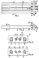
- Figures 1 and 2 are scrap top plane and side views respectively of a first form of tandem blade unit;
- Figures 3 and 4 are sections on the lines III-III and IV-IV, respectively, of Figure 2;
- Figures 5, 6 and 7 are scrap plan, front and end views, respectively, of a razor handle for use with the unit of Figures 1 to 4;
- Figures 8 and 9 are scrap top plan and side views of a second form of tandem blade unit;
- Figure 10 is a section on the line X-X of Figure 9;
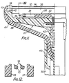
- Figure 11 is a scrap front view partially sectioned, of a razor fitted with the unit of Figures 8 to 10;
- Figure 12 is a section on the line XII-XII in Figure 11;
- Figure 13 is an end view of the razor of Figure 11;
- Figure 14 is a scrap top plan view of the razor of Figure 11, with the blade unit omitted in the interest of clarity; and
- Figures 15 and 16 are a scrap plan view and an end view respectively of a further form of blade unit.
- The unit shown in Figures 1 to 4 comprises a pair of blade supports 10 formed from round soft steel wire, press-deformed over the major part of their lengths to present opposed, parallel
flat surfaces 11. The end portions of the supports are generally circular, except for locally raisedtabs 12, and theoutermost end portions 13 turn downwardly. - Two
blade strips 14 each having a sharpenedlongitudinal edge 15 are secured to the upperflat surfaces 11, preferably by spot-welding or by the process described in our co-pending patent application G-B-A-2104430, with the sharpenededges 15 projecting forwardly, clear of thesupports 10. - The unit also includes a
guard member 16 and acap member 17, again formed from soft steel circular wire press-formed over the major part of their lengths to a generally rectangular cross-section. The round end portions are also formed with locally raisedtabs 18. - These four skin-engaging components are secured together in spaced parallel relation by
end links 19 formed of rigid plastics or elastomeric material moulded about the end portions of the four wires in the regions of thetabs - There is thus formed an integrated unit ready for assembly with a razor handle, in this case to form a disposable razor which is discarded as a whole when the cutting edges become unacceptably dulled. The unit is extremely compact, the links measuring only 8 mm x 3 mm.
- A razor handle to accept the above described unit is illustrated in Figures 5 to 7. The handle is a unitary plastics moulding comprising an
elongate grip portion 20 and a pair of upwardly divergingyoke arms 21 each terminating at an upwardly projectingear 22, recessed at 23 on its inner face to receive onelink 19 of the unit, and having in its outer wall four throughholes 24 to receive the end portions of the four wire members. - The tandem blade unit is simply fitted between the
ears 22, the resilience of theyoke arms 21 permitting sufficient deflection to engage the wire end portions in theholes 24. If thelinks 19 are made of elastomeric material, the projecting wire portions are normally held against the upper ends of theelongate holes 24, but under the forces imposed on the skin engaging members during shaving, the links may yield locally to permit small movements of the respective end portions independently of each other to provide additional degrees of conformance to the facial contours being shaved. The downturnedend portions 13 engage in the respectiveelongate holes 24 to key the supports against rotation about their longitudinal axes. Smallrectangular posts 25 are positioned to engage the flat outer sides of the cap andguard wire members - The tandem blade unit shown in Figures 8, 9 and 10 consists of two blade supports 10 and
blade strip 14 held in spaced parallel relation bymoulded end links 19. The unit differs from that of Figures 1 to 4 mainly in omitting themembers small flats 12A are formed in the regions embedded in the links instead of raisedtabs 12, to assist mechanical keying of the links to the wire supports. - Once again, the links may be of rigid or elastomeric material, but they are preferably elastomeric when intended for use with the razor illustrated in Figures 11 to 14, which will now be described in detail.
- The razor includes an
elongate grip portion 30 fast with atransverse head frame 31, to which is firmly secured a plastics moulding 32 comprising acentral part 33 secured to theframe 31, the end portions of which form bifurcatedspring fingers 34 integrally connected at their free ends to aguard member 36 and acap member 37 respectively, so that both of these members can be deflected resiliently at one end relative to the other, or at both ends in unison, for conformance with facial contours being shaved in use of the razor. Lateral movement of the cap and guard member is prevented by the engagement of depending pegs 38 intoguide slots 39 formed in theframe 31. - The ends of the
frame 31 turn upwardly andpresent recesses 40 open from above to receive theend links 19 of the tandem blade unit. In the closed condition of the razor, thelinks 19 are accommodated in the recesses and are firmly trapped in place by respectiveyoke arms 41 apertured to engage over the projecting ends of thesupports 10. - The
yoke arms 41 are urged into the closed, operative position illustrated, by ayoke spring 42, but can be swung outwardly in unison by operation of apush button 43, to an inoperative position in which they are clear of the recesses for the purpose of releasing a blade unit to be discarded, and of loading of a replacement blade unit. - The tandem blade units are preferably packed in containers which hold a number of such units to protect their cutting edges in transit and storage and which also facilitate loading of the units one-by-one as required onto a razor handle, without the user needing to touch the units. A suitable dispenser may be of the general form described in British Patent No. 1588986 but modified to take account of the fact that the individual wire-supported blades are now combined into an integrated unit.
- In another variant of the invention illustrated in Figures 15 and 16, the blade unit is generally similar to that of Figures 1 and 2, the main difference being that the projecting end portions of the blade supports 10 terminate flush with the outer faces of the respective
adjacent links 19, and each outer face has a projectingstud 19A of circular section which acts as a pivotal mounting means by which the unit can be grasped in a razor with freedom to pivot about the common axis of the respective studs in use of the completed razor. - Once again the unit may be incorporated as a permanent part of a disposable razor or as a replaceable cartridge.
- The blade unit of Figures 15 and 16 may also be employed in a razor which holds the unit in a fixed position, the
studs 19A in that case being used merely to assist in correct location of the unit on the razor head.
Claims (8)
Applications Claiming Priority (4)
| Application Number | Priority Date | Filing Date | Title |
|---|---|---|---|
| GB8234784 | 1982-12-07 | ||
| GB8234784 | 1982-12-07 | ||
| GB8327094 | 1983-10-11 | ||
| GB08327094A GB2131337B (en) | 1982-12-07 | 1983-10-11 | Safety razors |
Publications (2)
| Publication Number | Publication Date |
|---|---|
| EP0157776A1 EP0157776A1 (en) | 1985-10-16 |
| EP0157776B1 true EP0157776B1 (en) | 1988-04-27 |
Family
ID=26284611
Family Applications (1)
| Application Number | Title | Priority Date | Filing Date |
|---|---|---|---|
| EP84900087A Expired EP0157776B1 (en) | 1982-12-07 | 1983-12-07 | Safety razors |
Country Status (9)
| Country | Link |
|---|---|
| US (1) | US4516321A (en) |
| EP (1) | EP0157776B1 (en) |
| AU (1) | AU567842B2 (en) |
| CA (1) | CA1213430A (en) |
| DE (1) | DE3376392D1 (en) |
| ES (2) | ES276180Y (en) |
| GB (1) | GB2131337B (en) |
| IT (1) | IT1197751B (en) |
| WO (1) | WO1984002303A1 (en) |
Families Citing this family (20)
| Publication number | Priority date | Publication date | Assignee | Title |
|---|---|---|---|---|
| US4709477A (en) * | 1986-09-02 | 1987-12-01 | Warner-Lambert Company | Blade assembly featuring variable span |
| GB8710963D0 (en) * | 1987-05-08 | 1987-06-10 | Gillette Co | Safety razors |
| GB8712785D0 (en) * | 1987-06-01 | 1987-07-08 | Gillette Co | Blade units |
| US5416974A (en) * | 1990-03-27 | 1995-05-23 | The Gillette Company | Safety razors and blade units therefor |
| GB9006782D0 (en) * | 1990-03-27 | 1990-05-23 | Gillette Co | Safety razors and blade units therefor |
| DE69225324T2 (en) * | 1991-07-18 | 1998-11-05 | Warner Lambert Co | SHAVING HEAD WITH A VARIABLE SHAVING GEOMETRY |
| WO1994011163A1 (en) * | 1992-11-09 | 1994-05-26 | Warner-Lambert Company | Insert molded dynamic shaving system |
| US5546660A (en) * | 1994-09-30 | 1996-08-20 | Warner-Lambert Company | Dynamic razor head |
| US5787586A (en) * | 1996-04-10 | 1998-08-04 | The Gillette Company | Shaving system and method |
| US6173498B1 (en) * | 1996-08-05 | 2001-01-16 | The Gillette Company | Razor |
| US5953824A (en) * | 1997-09-23 | 1999-09-21 | Warner-Lambert Company | Razors providing pivoting and swivelling razor head support |
| GB2354474B8 (en) * | 1999-09-27 | 2008-01-29 | Gillette Co | Safety razors |
| GB2360479A (en) * | 2000-03-03 | 2001-09-26 | Enda Keaveney | Improvements in or relating to a razor |
| US7272991B2 (en) * | 2004-02-09 | 2007-09-25 | The Gillette Company | Shaving razors, and blade subassemblies therefor and methods of manufacture |
| US7621203B2 (en) * | 2004-02-09 | 2009-11-24 | The Gillette Company | Shaving razors, and blade subassemblies therefor and methods of manufacture |
| JP4950506B2 (en) * | 2006-02-14 | 2012-06-13 | 株式会社貝印刃物開発センター | razor |
| JP4950507B2 (en) * | 2006-02-14 | 2012-06-13 | 株式会社貝印刃物開発センター | razor |
| JP4977374B2 (en) * | 2006-02-14 | 2012-07-18 | 株式会社貝印刃物開発センター | razor |
| US9289909B2 (en) | 2009-04-15 | 2016-03-22 | Bic-Violex Sa | Razor cartridge and mechanical razor comprising such a cartridge |
| WO2018228709A1 (en) * | 2017-06-16 | 2018-12-20 | Bic-Violex Sa | Razor cartridges |
Family Cites Families (14)
| Publication number | Priority date | Publication date | Assignee | Title |
|---|---|---|---|---|
| US3660893A (en) * | 1969-03-26 | 1972-05-09 | Norman C Welsh | Replaceable blade unit for a safety razor |
| US3940853A (en) * | 1974-04-19 | 1976-03-02 | The Gillette Company | Shaving unit with blade tensioning means |
| US4084316A (en) * | 1974-10-08 | 1978-04-18 | The Gillette Company | Safety razors |
| GB1487834A (en) * | 1974-10-08 | 1977-10-05 | Gillette Co | Safety razors |
| GB1566505A (en) * | 1977-02-02 | 1980-04-30 | Gillette Co | Safety razor |
| GB1557843A (en) * | 1978-01-20 | 1979-12-12 | Gillette Co | Safety razors |
| GB1565415A (en) * | 1978-01-25 | 1980-04-23 | Gillette Co | Safety razors |
| GB1588986A (en) * | 1978-05-31 | 1981-05-07 | Gillette Co | Razor blade unit |
| GB2031782B (en) * | 1978-10-20 | 1982-06-16 | Wilkinson Sword Ltd | Razors |
| US4266340A (en) * | 1979-06-11 | 1981-05-12 | Warner-Lambert Company | Razor handle for mounting pivotable razor blade cartridges |
| DE3028430A1 (en) * | 1979-08-01 | 1981-02-19 | Wilkinson Sword Ltd | SHAVING UNIT |
| GB2055069B (en) * | 1979-08-01 | 1983-05-05 | Wilkinson Sword Ltd | Shaving units |
| US4270268A (en) * | 1979-12-07 | 1981-06-02 | The Gillette Company | Razor blade assembly |
| GB2104430B (en) * | 1981-08-24 | 1985-05-09 | Gillette Co | Securing a razor blade to a support |
-
1983
- 1983-10-11 GB GB08327094A patent/GB2131337B/en not_active Expired
- 1983-11-28 US US06/555,801 patent/US4516321A/en not_active Expired - Lifetime
- 1983-11-28 CA CA000442029A patent/CA1213430A/en not_active Expired
- 1983-12-06 IT IT8349444A patent/IT1197751B/en active
- 1983-12-06 ES ES1983276180U patent/ES276180Y/en not_active Expired
- 1983-12-07 DE DE8484900087T patent/DE3376392D1/en not_active Expired
- 1983-12-07 WO PCT/GB1983/000322 patent/WO1984002303A1/en active IP Right Grant
- 1983-12-07 EP EP84900087A patent/EP0157776B1/en not_active Expired
- 1983-12-07 AU AU23365/84A patent/AU567842B2/en not_active Ceased
-
1984
- 1984-06-16 ES ES1984280052U patent/ES280052Y/en not_active Expired
Also Published As
| Publication number | Publication date |
|---|---|
| ES276180U (en) | 1986-03-01 |
| GB8327094D0 (en) | 1983-11-09 |
| CA1213430A (en) | 1986-11-04 |
| IT8349444A0 (en) | 1983-12-06 |
| GB2131337A (en) | 1984-06-20 |
| DE3376392D1 (en) | 1988-06-01 |
| ES280052Y (en) | 1985-10-16 |
| EP0157776A1 (en) | 1985-10-16 |
| ES280052U (en) | 1985-03-01 |
| AU567842B2 (en) | 1987-12-03 |
| US4516321A (en) | 1985-05-14 |
| WO1984002303A1 (en) | 1984-06-21 |
| GB2131337B (en) | 1985-10-30 |
| IT1197751B (en) | 1988-12-06 |
| ES276180Y (en) | 1986-10-01 |
| AU2336584A (en) | 1984-07-05 |
Similar Documents
| Publication | Publication Date | Title |
|---|---|---|
| EP0157776B1 (en) | Safety razors | |
| US9434079B2 (en) | Shaving razors and shaving cartridges | |
| CA2557281C (en) | Shaving system | |
| EP1722944B1 (en) | Razors and shaving cartridges with guard | |
| EP1722939B1 (en) | Shaving cartridges and razors | |
| US7966731B2 (en) | Shaving razors and shaving cartridges with trimming assembly and anode-cathode cell | |
| EP0290025B1 (en) | Improvement in or relating to safety razors | |
| EP1722945B1 (en) | Shaving razor with additional trimming blade | |
| US20060179661A1 (en) | Shaving cartridges and razors | |
| JPS60500004A (en) | Safety razor and safety razor blade unit |
Legal Events
| Date | Code | Title | Description |
|---|---|---|---|
| PUAI | Public reference made under article 153(3) epc to a published international application that has entered the european phase |
Free format text: ORIGINAL CODE: 0009012 |
|
| 17P | Request for examination filed |
Effective date: 19841221 |
|
| AK | Designated contracting states |
Designated state(s): DE FR NL |
|
| 17Q | First examination report despatched |
Effective date: 19860930 |
|
| GRAA | (expected) grant |
Free format text: ORIGINAL CODE: 0009210 |
|
| AK | Designated contracting states |
Kind code of ref document: B1 Designated state(s): DE FR NL |
|
| REF | Corresponds to: |
Ref document number: 3376392 Country of ref document: DE Date of ref document: 19880601 |
|
| ET | Fr: translation filed | ||
| PLBE | No opposition filed within time limit |
Free format text: ORIGINAL CODE: 0009261 |
|
| STAA | Information on the status of an ep patent application or granted ep patent |
Free format text: STATUS: NO OPPOSITION FILED WITHIN TIME LIMIT |
|
| 26N | No opposition filed | ||
| PGFP | Annual fee paid to national office [announced via postgrant information from national office to epo] |
Ref country code: FR Payment date: 19981118 Year of fee payment: 16 |
|
| PGFP | Annual fee paid to national office [announced via postgrant information from national office to epo] |
Ref country code: DE Payment date: 19981120 Year of fee payment: 16 |
|
| PGFP | Annual fee paid to national office [announced via postgrant information from national office to epo] |
Ref country code: NL Payment date: 19981126 Year of fee payment: 16 |
|
| PG25 | Lapsed in a contracting state [announced via postgrant information from national office to epo] |
Ref country code: NL Free format text: LAPSE BECAUSE OF NON-PAYMENT OF DUE FEES Effective date: 20000701 |
|
| PG25 | Lapsed in a contracting state [announced via postgrant information from national office to epo] |
Ref country code: FR Free format text: LAPSE BECAUSE OF NON-PAYMENT OF DUE FEES Effective date: 20000831 |
|
| NLV4 | Nl: lapsed or anulled due to non-payment of the annual fee |
Effective date: 20000701 |
|
| PG25 | Lapsed in a contracting state [announced via postgrant information from national office to epo] |
Ref country code: DE Free format text: LAPSE BECAUSE OF NON-PAYMENT OF DUE FEES Effective date: 20001003 |
|
| REG | Reference to a national code |
Ref country code: FR Ref legal event code: ST |