EP0157718A2 - Drehbares Signal für Verkehrslenkung - Google Patents
Drehbares Signal für Verkehrslenkung Download PDFInfo
- Publication number
- EP0157718A2 EP0157718A2 EP85630035A EP85630035A EP0157718A2 EP 0157718 A2 EP0157718 A2 EP 0157718A2 EP 85630035 A EP85630035 A EP 85630035A EP 85630035 A EP85630035 A EP 85630035A EP 0157718 A2 EP0157718 A2 EP 0157718A2
- Authority
- EP
- European Patent Office
- Prior art keywords
- housing
- section
- cover plate
- traffic signal
- light
- Prior art date
- Legal status (The legal status is an assumption and is not a legal conclusion. Google has not performed a legal analysis and makes no representation as to the accuracy of the status listed.)
- Withdrawn
Links
- 238000013459 approach Methods 0.000 description 5
- 238000005192 partition Methods 0.000 description 5
- 206010021033 Hypomenorrhoea Diseases 0.000 description 4
- 238000010586 diagram Methods 0.000 description 2
- 208000006992 Color Vision Defects Diseases 0.000 description 1
- 230000004397 blinking Effects 0.000 description 1
- 201000007254 color blindness Diseases 0.000 description 1
- 230000005611 electricity Effects 0.000 description 1
- 230000004048 modification Effects 0.000 description 1
- 238000012986 modification Methods 0.000 description 1
Images

Classifications
-
- G—PHYSICS
- G08—SIGNALLING
- G08G—TRAFFIC CONTROL SYSTEMS
- G08G1/00—Traffic control systems for road vehicles
- G08G1/09—Arrangements for giving variable traffic instructions
- G08G1/095—Traffic lights
Definitions
- the present invention relates to traffic signals, such as are provided at the intersections and other locations of public roads and highways for controlling the traffic therethrough.
- the traffic signals in present use include a green light which is energized to direct the traffic to "go,” and a red light which is energized to direct the traffic to "stop.” They frequently also include a "caution” yellow light energized at the end of the energization period of the green light to alert the traffic of the impending change of the light from green to red; and some traffic signals also energize the "caution” yellow light at the end of the energization period of the red light to alert the traffic of the impending change from red to green.
- An object of the present invention is to provide a traffic signal having advantages in the above respects. More particularly, an object of the present invention is to provide a traffic signal which also continuously informs the drivers of the current point in the traffic signal cycle at any particular instant such that each driver is aware of the time left for the respective portion of the traffic signal then energized and can therefore control his vehicle accordingly well before he approaches the intersection.
- a traffic signal comprising: a housing; a source of green light in a first section of the housing on one side of its horizontal axis; a source of red light in a second section of the housing on the opposite side of its horizontal axis; a cover plate closing one end of the housing; a drive for cyclically rotating the cover plate about the housing horizontal axis; and a light-transmitting window carried by the cover plate on one side of its rotary axis, such that for a first portion of each rotary cycle of the cover plate, the window traverses the first section of the housing to transmit green light therethrough, and for a second portion of each rotary cycle of the cover plate, the window traverses the second section of the housing to transmit red light therethrough.
- the housing further includes a source of yellow light in a third section thereof, such that for a third portion of each rotary cycle of the cover plate, the window traverses the third section of the housing to transmit yellow light therethrough.
- Such traffic signal provides continuous indications to the vehicle drivers of the point the traffic signal cycle is at any particular instant and also of the time remaining until the respective portion of the signal cycle terminates and the next portion starts, so that the driver can control his vehicle accordingly.
- Such a traffic signal thus not only avoids the dangerous situation which may be created by the presently used traffic signals as described above, but also relieves the vehicle drivers of the apprehension of a possible signal change at a critical point as they approach the traffic signal at the intersection.
- Other advantages of the traffic signal of the present invention are that they consume substantially less electricity, and can be constructed more compactly, than the conventional traffic signals.
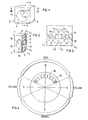
- the traffic signal illustrated in Figs. 1-3 of the drawings comprises a housing 2 including a rear wall 3, front wall 4, top wall 5, bottom wall 6, and end walls 7, 8.
- the interior of housing 2 is provided with a first pair of parallel partitions 9, 10, and a second pair of parallel partitions 11, 12, extending perpendicularly to and between partitions 9, 10.
- Partitions 9-12 thus divide the interior of housing 2 into five sections or compartments, namely: two large compartments C 1 , C 2 at the top and bottom of the housing, respectively; two smaller compartments C 3 , C 4 on opposite sides of the housing and between the larger compartments C 1 , C 2 ; and a central compartment C 5 bounded by the other four compartments.
- the central, fifth compartment C 5 does not include a lamp, but is used for another purpose as described below.
- the front wall 4 of housing 2 is closed by a circular cover plate 15 which is mounted for rotation about the central horizontal axis 16 of the housing.
- Cover plate 15 is rotated by an electric motor 17 supported on partition 10 within the central compart-. ment C 5 so as to be xoaxial with the central horizontal axis 16 of the housing.
- Rotatable cover plate 15 is opaque but includes a transparent window 18 of circular configuration laterally of the central horizontal axis 16 of the housing and its cover plate 15.
- Window 18 is so located that during each cycle of rotation of its cover plate 15, the window traverses the four sections or compartments of housing 2 in succession, thereby to transmit through the window the colored light of the respective housing compartment with which it is aligned during the respective portion of the rotational cycle of the cover plate.
- Motor 17 is driven to rotate cover plate 15, and thereby its window 18, in the clockwise direction so that window 18 traverses compartments C 1 -C 4 in sequence and becomes aligned with each compartment to project the color of that compartment during a portion of each cycle.
- each cycle of rotation of cover plate 15 results in projecting through window 18 a red “stop” light and a green “go” light in separate phases of each cycle, with a yellow “caution” light being displayed in a smaller portion of the cycle just before each switch-over from red-to-green and green-to-red. It will also be seen that just before each switch-over, a part of window 18 will be of one color, that preceding the switch-over, and another part will be of the other color, subsequent to the switch-over.
- the viewer is immediately apprised of the exact point in the cycle at which the traffic signal is at the instant, and therefore how much time is left before there will be a switch-over in the traffic signal.
- the vehicle driver therefore can control the vehicle accordingly, since he knows whether he has sufficient time to traverse the intersection, or whether he should start to slow-down the vehicle so as to come to a safe stop before arriving at the intersection.
- the illustrated traffic signal thus avoids the possibly dangerous situation discussed above resulting from a sudden change in traffic signals at a critical point during the approach to the intersection. It also relieves the vehicle driver of the apprehension that such a sudden change may occur as he approaches the intersection.
- Fig. 5 illustrates another traffic signal constructed in accordance with the present invention, which provides not only light signals for directing traffic, but also other signals, such as arrow signals (or word signals) for directing the traffic.
- Figs. 6a and 6b illustrate the operation of the traffic signal of Fig. 5.
- the traffic signal illustrated comprises a housing 102 whose interior includes a single lamp 104, e.g. a circular fluorescent lamp, and is closed by a screen 105 having three colored light-transmissive sections, namely an upper red section 106, an intermediate yellow section 107, and a lower green section 108, separated along straight parallel lines 109, 110.
- housing 102 includes indicia, in the form of an arrow 112, which is covered by a blue light-transmissive screen.
- the front wall of housing 102 is closed by a circular cover plate 115 mounted for rotation about the central horizontal axis of the housing.
- Cover plate 115 is rotated by an electric motor 117 mounted centrally of the housing rear wall.
- Rotatable cover plate 115 is opaque but also includes a transparent window 118 of circular configuration and disposed laterally of the central horizontal axis of the housing, such that rotation of the cover plate by motor 117 causes window 118 to traverse the red housing section 106, yellow housing section 107, green housing section 108, and yellow housing section 107, in that sequence.
- Cover plate 115 is further formed with an elongated slot 120 along its outer periphery alignable with indicia 112 during the appropriate portion of the cover plate rotary cycle. This is more particularly illustrated in Figs. 6a and 6b.
- indicia 112 is normally concaled by cover plate 115, but when the cover plate arrives at the appropriate portion of the cycle wherein a left turn is permitted, its slot 120 uncovers indicia 112 to signal to the traffic that a left turn is permitted.
- indicia may be used instead of the left-turn arrow 112.
- word directions such as "walk,” “stop,” or “caution,” for example, to aid persons suffering from color blindness.
- Fig. 5 illustrates a further modification, in that it includes means for returning the cover plate to its home position when the electric motor 117 is de-energized.
- the returning means comprises a weight 122 secured to the motor drive for biasing the motor to a home position when the motor is de-energized.
- This home position would be selected to align window 118 of the cover plate 115 with a predetermined color section of the housing, e.g., the red section or the yellow section, according to the particular application of the traffic signal.
- the yellow "caution" section could be non-illuminated or blackened, to avoid the yellow being displayed at the same time as the green or red.
- intersection includes a traffic signal facing each of the four (or more) directions of traffic
- one such signal may be provided for each direction.
- the traffic signal housing could be sectioned to project only the red “stop” light and the green “go” light, or only-one of the two yellow “caution” lights.
- the traffic signal could also be embodied in a portable unit containing a battery supply for use in emergency situations.
Landscapes
- Physics & Mathematics (AREA)
- General Physics & Mathematics (AREA)
- Traffic Control Systems (AREA)
Applications Claiming Priority (2)
| Application Number | Priority Date | Filing Date | Title |
|---|---|---|---|
| IL71436A IL71436A0 (en) | 1984-04-03 | 1984-04-03 | Rotatable signal for directing traffic |
| IL71436 | 1984-04-03 |
Publications (1)
| Publication Number | Publication Date |
|---|---|
| EP0157718A2 true EP0157718A2 (de) | 1985-10-09 |
Family
ID=11054955
Family Applications (1)
| Application Number | Title | Priority Date | Filing Date |
|---|---|---|---|
| EP85630035A Withdrawn EP0157718A2 (de) | 1984-04-03 | 1985-03-27 | Drehbares Signal für Verkehrslenkung |
Country Status (2)
| Country | Link |
|---|---|
| EP (1) | EP0157718A2 (de) |
| IL (1) | IL71436A0 (de) |
Cited By (1)
| Publication number | Priority date | Publication date | Assignee | Title |
|---|---|---|---|---|
| CN108877260A (zh) * | 2018-08-12 | 2018-11-23 | 曹进 | 一种便携式节能型移动交通信号灯 |
-
1984
- 1984-04-03 IL IL71436A patent/IL71436A0/xx unknown
-
1985
- 1985-03-27 EP EP85630035A patent/EP0157718A2/de not_active Withdrawn
Cited By (2)
| Publication number | Priority date | Publication date | Assignee | Title |
|---|---|---|---|---|
| CN108877260A (zh) * | 2018-08-12 | 2018-11-23 | 曹进 | 一种便携式节能型移动交通信号灯 |
| CN108877260B (zh) * | 2018-08-12 | 2024-05-03 | 深圳市天深达科技有限公司 | 一种便携式节能型移动交通信号灯 |
Also Published As
| Publication number | Publication date |
|---|---|
| IL71436A0 (en) | 1984-07-31 |
Similar Documents
| Publication | Publication Date | Title |
|---|---|---|
| US2736002A (en) | oriel | |
| US6175313B1 (en) | Attachment to traffic light apparatus for visual indication of traffic light duration | |
| GB2311265A (en) | Vehicle blind spot detection and display system | |
| US4590455A (en) | Traffic control system using timed blink signal and road marker | |
| US4791402A (en) | Front signal light for automotive vehicle | |
| US4191939A (en) | Vehicle parking signaling device | |
| US2517173A (en) | Safety signal device for vehicles | |
| EP0157718A2 (de) | Drehbares Signal für Verkehrslenkung | |
| US2503336A (en) | Traffic signal for vehicles | |
| US3656104A (en) | Advance anti-lockout vehicle parking signal having adjustable deck mounted brackets | |
| US4559517A (en) | Warning system for school buses | |
| US1970080A (en) | Automobile signal | |
| US3529287A (en) | Traffic circle amber light | |
| US4558299A (en) | Turn-on-red traffic signal | |
| JPH07160990A (ja) | 自動交通整理装置 | |
| US2814796A (en) | Vehicle speed indicator | |
| US3200371A (en) | Traffic signal lights | |
| US2396971A (en) | Traffic signal | |
| US2588739A (en) | Traffic light accessory | |
| US3289629A (en) | Traffic signal | |
| US1988633A (en) | Traffic signal | |
| US2490585A (en) | Electrically operated time lapse traffic signal | |
| US2119049A (en) | Traffic semaphore | |
| US2506330A (en) | Safety signal for motor vehicles | |
| KR200379396Y1 (ko) | 차량용 표시장치 |
Legal Events
| Date | Code | Title | Description |
|---|---|---|---|
| PUAI | Public reference made under article 153(3) epc to a published international application that has entered the european phase |
Free format text: ORIGINAL CODE: 0009012 |
|
| AK | Designated contracting states |
Designated state(s): AT BE CH DE FR GB IT LI NL SE |
|
| STAA | Information on the status of an ep patent application or granted ep patent |
Free format text: STATUS: THE APPLICATION IS DEEMED TO BE WITHDRAWN |
|
| 18D | Application deemed to be withdrawn |
Effective date: 19870401 |