EP0157694B1 - Palier magnétique radial actif à rotor massif pour l'amortissement des fréquences critiques - Google Patents
Palier magnétique radial actif à rotor massif pour l'amortissement des fréquences critiques Download PDFInfo
- Publication number
- EP0157694B1 EP0157694B1 EP85400549A EP85400549A EP0157694B1 EP 0157694 B1 EP0157694 B1 EP 0157694B1 EP 85400549 A EP85400549 A EP 85400549A EP 85400549 A EP85400549 A EP 85400549A EP 0157694 B1 EP0157694 B1 EP 0157694B1
- Authority
- EP
- European Patent Office
- Prior art keywords
- rotor
- windings
- winding
- supplied
- magnetic bearing
- Prior art date
- Legal status (The legal status is an assumption and is not a legal conclusion. Google has not performed a legal analysis and makes no representation as to the accuracy of the status listed.)
- Expired
Links
Images


Classifications
-
- F—MECHANICAL ENGINEERING; LIGHTING; HEATING; WEAPONS; BLASTING
- F16—ENGINEERING ELEMENTS AND UNITS; GENERAL MEASURES FOR PRODUCING AND MAINTAINING EFFECTIVE FUNCTIONING OF MACHINES OR INSTALLATIONS; THERMAL INSULATION IN GENERAL
- F16C—SHAFTS; FLEXIBLE SHAFTS; ELEMENTS OR CRANKSHAFT MECHANISMS; ROTARY BODIES OTHER THAN GEARING ELEMENTS; BEARINGS
- F16C32/00—Bearings not otherwise provided for
- F16C32/04—Bearings not otherwise provided for using magnetic or electric supporting means
- F16C32/0406—Magnetic bearings
- F16C32/044—Active magnetic bearings
- F16C32/0444—Details of devices to control the actuation of the electromagnets
-
- F—MECHANICAL ENGINEERING; LIGHTING; HEATING; WEAPONS; BLASTING
- F16—ENGINEERING ELEMENTS AND UNITS; GENERAL MEASURES FOR PRODUCING AND MAINTAINING EFFECTIVE FUNCTIONING OF MACHINES OR INSTALLATIONS; THERMAL INSULATION IN GENERAL
- F16C—SHAFTS; FLEXIBLE SHAFTS; ELEMENTS OR CRANKSHAFT MECHANISMS; ROTARY BODIES OTHER THAN GEARING ELEMENTS; BEARINGS
- F16C32/00—Bearings not otherwise provided for
- F16C32/04—Bearings not otherwise provided for using magnetic or electric supporting means
- F16C32/0406—Magnetic bearings
- F16C32/044—Active magnetic bearings
- F16C32/0474—Active magnetic bearings for rotary movement
- F16C32/048—Active magnetic bearings for rotary movement with active support of two degrees of freedom, e.g. radial magnetic bearings
Definitions
- the present invention relates to an active radial magnetic bearing comprising a rotating field stator composed of a frame and electromagnet windings regularly distributed around the periphery of the stator, a rotor secured to a rotating shaft and arranged in gaze of the stator, of the detectors of the radial position of the rotor relative to the stator, and of the control circuits to modify the current flowing in the electromagnet windings according to the signals delivered by the position detectors, each winding d electromagnet comprising, connected in series, a first winding supplied in a first direction and a second winding supplied in the opposite direction to the first winding and offset angularly with respect to the first winding.
- French patent FR-A-2336603 describes precisely a device for damping the critical frequencies of a rotor mounted on radial active magnetic bearings.
- This device which includes means for selective amplification of the gain of the magnetic bearing control circuit, in phase or in phase advance, in a narrow frequency band centered on a frequency equal to the rotation speed of the rotor, operates In an acceptable way.
- the magnetic bearings must necessarily include an annular rotor armature constituted by a laminated ferromagnetic material. This is not easily achievable on all rotating machines fitted with very large diameter shafts, and is practically not applicable to existing machines without their complete dismantling. Laminating is also often risky if the rotational speeds must be very high.
- radial magnetic bearings with axial magnetic flux of the type shown in FIG. 1, in which bearing electromagnets U-shaped have poles located on either side of a plane of symmetry perpendicular to the axis of the rotor.
- a non-laminated, solid or tubular rotor can be used to allow damping when passing critical frequencies.
- This embodiment has limits, however, insofar as the magnetic forces cannot be very large and the penetration of the magnetic flux into the rotor cannot be deep.
- the rotor is heated by eddy currents because the magnetic field which in principle rotates in synchronism with the rotor is not sinusoidal.
- Document FR-A-2 052 314 also discloses a magnetic bearing system for a rotor with essentially vertical axis of rotation, which employs electromagnetic active stabilization means cooperating with lift magnets creating a main magnetic field. constant. It is indicated in this document that the electromagnetic stabilization means can be requested by a rotating field used for driving the rotor. However, in this case, the presence of a rotary field which aims, as in a conventional rotary field motor, to create a torque for driving the rotor in rotation, cannot contribute to improving the proper function of the bearing system magnetic.
- the present invention aims to remedy the aforementioned drawbacks and to make it possible to easily achieve effective damping of the disturbances appearing at the passage of the critical frequencies, even for large diameter rotors requiring magnetic bearings with high induction magnetic field.
- an active radial magnetic bearing of the type mentioned at the beginning characterized in that the rotor is full and made in a massive manner, without lamination, in that at least three windings are provided, each comprising a pair of non-diametrically opposite windings, each pair of windings constituting a winding is supplied with direct current having an invariable direction of flow from a direct current amplifier, in that there is provided a device for detecting the rotation of the rotor, and in that the electromagnet windings are successively supplied in turn, each using its own amplifier, from the servo circuits, synchronized with the rotation of the rotor, so to produce a rotating magnetic field with radial flux which follows the movements of the rotor and exerts on the rotor a rotating radial force.
- the rotor hardly sees any variations in magnetic field on a revolution. This therefore allows effective damping at the passage of critical frequencies without producing any particular heating by eddy currents.
- the first winding of a winding considered is superimposed on the second winding of the penultimate winding supplied before the winding considered.
- the first winding of each winding is interposed between the first and second windings of the winding supplied immediately previously.
- the magnetic bearing comprises eight windings each comprising a pair of windings and each supplied from its own amplifier.
- first and second windings of each of the windings are offset by 90 ° relative to each other.
- the magnetic bearing comprises ten pairs of windings each comprising a pair of windings and each supplied from its own amplifier.
- the magnetic bearing according to the invention is thus particularly suitable for being mounted at the end of a large diameter shaft.
- FIG. 1 shows a radial magnetic bearing with axial flux comprising U-shaped electromagnets 1 each having pole pieces 3, 4 symmetrical with respect to a radial plane perpendicular to the axis of the rotor 2. Windings 5 , 6 traversed by excitation currents 1 1 , 1 2 respectively are arranged on the pole pieces 3, 4.
- This type of bearing creates a magnetic flux according to the dotted lines referenced 7, that is to say a flux which flows axially at the periphery of the rotor 2 which can be solid or tubular and does not require lamination.
- Such a type of magnetic bearing makes it possible to create damping during the passage of the rotor at a critical speed, but nevertheless has drawbacks as indicated above in the present description and cannot be adapted to all types of rotating machines.
- Figures 2 to 4 relate to radial magnetic bearings with radial flux which, unlike the bearing of Figure 1, can adapt to large diameter rotors and rotors rotating at high speed.
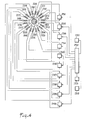
- stator 100 of radial magnetic bearing comprising, mounted in notches 121 of a fixed frame 120, a plurality of windings 101 to 108, 111 to 118.
- FIG. 4 For clarity, in the figure 2, as also in the variant of FIG. 4, only the electromagnet windings have been represented symbolically.
- each pair of windings 101, 111; 102, 112; ... 108, 118 constituting a winding is supplied simultaneously by a contrary current from an own amplifier 11, -18 providing a direct current whose direction of flow is invariable.
- the first winding 101, ... 108 is supplied in a first direction and the second winding 111, ... 118 is supplied in the opposite direction to the first winding.
- the second winding 111, ... 118 is angularly offset by 90 ° relative to the first winding 101, ... 108.
- the different pairs of coils 101, 111; 102, 112; ... 108, 118 arranged successively on the periphery of the stator 100 and coming successively opposite the same zone of the rotor 2 when the latter is in rotation, are successively supplied in turn by the circuit d servo 20.
- the servo circuit 20 thus supplies in turn and successively in this order the amplifiers 11, 12, ... 18, the rotor 2 rotating in the direction of the arrow shown in FIG. 2.
- the control circuit 20 is constituted in a conventional manner and makes it possible to adjust the value of the current applied to the windings of stator electromagnets as a function of the signals supplied by detectors 31, 32 of the radial position of the rotor 2 detecting the displacements of the rotor in two orthogonal directions in a radial plane.
- the circuit33 making it possible to switch the power supply to the different amplifiers 11, 12, ... 18 comprises a member for detecting the speed of rotation of the rotor 2, in order to allow synchronization of the successive power supply of the different amplifiers 11 , ... 18 with the rotation of the rotor.
- Each pair of coils 101, 111; 102, 112; ... 118 exerts on the rotor a resulting action which, considered with respect to the stator, is offset by with respect to the action of the pair of windings excited immediately above, n being the total number of pairs of windings distributed over the stator.
- Switching pulses can thus be produced as a function of the rotation of the rotor 2, from the signals delivered by the speed detection member each time the rotor has turned by an angle 21t.
- the location n of the pairs of stator windings being well defined with respect to the detectors of the radial position of the rotor 31, 32, each amplifier 11, ... 18 successively supplied by the servo circuit 20 as a function of the output of the pulses switching elements can exert on the rotor an action of attraction adapted according to the signals delivered by the detectors 31, 32 in order to tend to maintain the rotor in a predetermined equilibrium position.
- the first winding 101, ... 108 of a given winding is superimposed on the second winding 117, ... 116 of the penultimate winding supplied before said given winding.
- the various first windings 101, ... 108 of successive windings are regularly distributed, being angularly distant by 45 ° from each other.
- the different second windings 111, ... 118 of successive windings are regularly spaced angularly by 45 ° from each other.
- the first winding 101, ... 108 of each winding is interposed between the first and second windings 108, 118; ... 107, 117 of the winding supplied immediately previously and located angularly halfway between those -this.
- the different windings are identical to each other and the amplifiers 11 to 18 also each have identical characteristics. This guarantees the production of a rotating magnetic field with radial flux which follows the movements of the rotor 2. The latter therefore does not see significant variations in the magnetic field over a revolution. This allows the use of a massive rotor while ensuring damping during the passage of critical frequencies.
- the radial magnetic flux ⁇ o flowing in the rotor 2 and the armature 120 of the stator 100 of the bearing at an instant t . during which the windings 101, 111 of the first winding are supplied from the amplifier 11 while none of the other windings receives current has been shown in broken lines in FIG. 3. Also shown in this same figure , in dotted lines, the radial magnetic flux ⁇ 1 circulating in the rotor 2 and the armature 120 of the stator 100 of the bearing at an instant t 1 corresponding to a rotation of the rotor by 45 ° and during which the windings 102, 112 of the second winding are supplied from the amplifier 12 while all the other windings are inactive and receive no current.
- the resulting force F o exerted on the rotor at time t o and due to the flow ⁇ o created by the coils 101, 111 and the resulting force F 1 exerted on the rotor at time t 1 and due to the flow 0 1 , created by the windings 102, 112 are represented by arrows in FIG. 3. It can be seen that the resulting force exerted on the rotor follows the rotation of the latter, which tends to create damping.
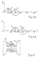
- FIGS. 5a and 5b represent respectively for times to and t, the shape of the magnetic induction B (curve 8 in solid line) and that of the force F due to the magnetic field and exerted on the rotor (curve 9 in broken line ), as a function of the angular position relative to an origin located at the point 0 in FIG. 3 offset from the center of the first coil 101.
- the shape of the magnetic induction B is sinusoidal while the force F (components F 01 , F 02 , F 11 , F 12 in Figures 3 and 5a, 5b), proportional to the square of the magnetic induction B, always keeps the same sign.
- FIG. 5b thus corresponds to an instant when the coils 103 and 113 are supplied from the amplifier 13 while FIG. 5a corresponds to the instant t o at which the coils 101 and 111 are supplied from the amplifier 11.
- the magnetic field created can however have an even more regular sinusoidal character if ten pairs of coils 201, 221 are used; 202, 222; ... 210, 230 associated with ten amplifiers 231 to 240, as shown in FIG. 4.
- the fluctuations of the magnetic field in the rotor are very greatly reduced, which allows the times to use a simple massive rotor and to obtain the creation of a damping force allowing an easy crossing of critical speeds.
- the detectors 251, 252 and the circuits 250, 253 correspond respectively to the elements referenced 31, 32 and 20, 33 in FIG. 2.
- the amplifiers 231 to 240 may have characteristics similar to those of the amplifiers 11 to 18.
- the coils 201, 221; 202, 222; ... 210, 230 are regularly distributed around the periphery of the stator, two successive windings 201, 202 or 221, 222 being offset by approximately 36 °, and there is an overlap between the windings, the winding 202 for example being interposed between the coils 201 and 221.
- the second coils 221, 222, ... 230 of the pairs of coils are also arranged in the same stator notches as the first coils 203, 204, ... 202 pairs of different windings, with regular shifts.
- FIG. 6 shows an example of application of the invention to large machines having several successive sections 301, 302 with shafts 311, 312 terminated by a free end part 321, 322 of increased section.
- the present invention makes it possible to have a stator 340 provided with electromagnet windings 341 directly around the massive end portions 321, 322. produced in the manner described above for example with eight or ten pairs of windings supplied sequentially. This contributes to achieving an efficient magnetic bearing constituting an active damper, in particular facilitating the passage of critical speeds.
- the radial bearing according to the invention avoids the production of lamination on the shaft ends 311, 312 and can therefore be applied regardless of the diameter or the speed of rotation of the shaft.
- the location on the end portions 321, 322 of increased section allows in particular an embodiment on existing machines where the free space for the establishment of a bearing or a damper is limited.
Landscapes
- Engineering & Computer Science (AREA)
- General Engineering & Computer Science (AREA)
- Mechanical Engineering (AREA)
- Physics & Mathematics (AREA)
- Electromagnetism (AREA)
- Magnetic Bearings And Hydrostatic Bearings (AREA)
Applications Claiming Priority (2)
| Application Number | Priority Date | Filing Date | Title |
|---|---|---|---|
| FR8404650 | 1984-03-26 | ||
| FR8404650A FR2561729B1 (fr) | 1984-03-26 | 1984-03-26 | Palier magnetique radial actif a rotor massif pour l'amortissement des frequences critiques |
Publications (2)
| Publication Number | Publication Date |
|---|---|
| EP0157694A1 EP0157694A1 (fr) | 1985-10-09 |
| EP0157694B1 true EP0157694B1 (fr) | 1988-12-28 |
Family
ID=9302449
Family Applications (1)
| Application Number | Title | Priority Date | Filing Date |
|---|---|---|---|
| EP85400549A Expired EP0157694B1 (fr) | 1984-03-26 | 1985-03-22 | Palier magnétique radial actif à rotor massif pour l'amortissement des fréquences critiques |
Country Status (6)
| Country | Link |
|---|---|
| US (1) | US4866318A (enExample) |
| EP (1) | EP0157694B1 (enExample) |
| JP (1) | JPS60220220A (enExample) |
| CA (1) | CA1249321A (enExample) |
| DE (1) | DE3567074D1 (enExample) |
| FR (1) | FR2561729B1 (enExample) |
Cited By (1)
| Publication number | Priority date | Publication date | Assignee | Title |
|---|---|---|---|---|
| CN109026995A (zh) * | 2018-07-20 | 2018-12-18 | 南京航空航天大学 | 一种抗磁悬浮微型轴承转子系统 |
Families Citing this family (19)
| Publication number | Priority date | Publication date | Assignee | Title |
|---|---|---|---|---|
| JPH01116318A (ja) * | 1987-10-28 | 1989-05-09 | Natl Aerospace Lab | 能動形磁気軸受 |
| US5216308A (en) * | 1989-05-25 | 1993-06-01 | Avcon-Advanced Controls Technology, Inc. | Magnetic bearing structure providing radial, axial and moment load bearing support for a rotatable shaft |
| DE69019491T2 (de) * | 1989-12-29 | 1996-02-22 | Ebara Corp | Verschiebungssensor vom Induktionstyp mit Unempfindlichkeit gegenüber externen magnetischen Feldern. |
| US5059845A (en) * | 1990-05-07 | 1991-10-22 | Mechanical Technology Incorporated | Active magnetic bearing device for controlling rotor vibrations |
| US5250865A (en) * | 1992-04-30 | 1993-10-05 | Avcon - Advanced Controls Technology, Inc. | Electromagnetic thrust bearing for coupling a rotatable member to a stationary member |
| US5514924A (en) * | 1992-04-30 | 1996-05-07 | AVCON--Advanced Control Technology, Inc. | Magnetic bearing providing radial and axial load support for a shaft |
| US5315197A (en) * | 1992-04-30 | 1994-05-24 | Avcon - Advance Controls Technology, Inc. | Electromagnetic thrust bearing using passive and active magnets, for coupling a rotatable member to a stationary member |
| US5455472A (en) * | 1993-07-06 | 1995-10-03 | United Technologies Corporation | Moment imparting bearings for controlling shaft deflection |
| FR2720456B1 (fr) * | 1994-05-25 | 1996-08-14 | Aerospatiale | Palier magnétique radial actif sans aimants et à faible trainée. |
| US5578880A (en) * | 1994-07-18 | 1996-11-26 | General Electric Company | Fault tolerant active magnetic bearing electric system |
| US5572079A (en) * | 1994-12-21 | 1996-11-05 | Magnetic Bearing Technologies, Inc. | Magnetic bearing utilizing brushless generator |
| US5821656A (en) * | 1995-07-11 | 1998-10-13 | United Technologies Corporation | Magnetic bearing with reduced control-flux-induced rotor loss |
| GB2303412B (en) * | 1995-07-14 | 1999-08-11 | Glacier Metal Co Ltd | Electromagnetic bearing |
| EP1063753B1 (de) * | 1999-06-22 | 2009-07-22 | Levitronix LLC | Elektrischer Drehantrieb mit einem magnetisch gelagerten Rotor |
| US7023118B1 (en) | 2002-03-14 | 2006-04-04 | The United States Of America As Represented By The Administrator Of National Aeronautics And Space Administration | System for controlling a magnetically levitated rotor |
| DE102006018267B4 (de) * | 2006-04-20 | 2008-08-14 | Technische Universität Dresden | Verfahren zum Ansteuern aktiver Magnetlager |
| GB2517442A (en) * | 2013-08-20 | 2015-02-25 | Univ Catholique Louvain | Radial electrodynamic bearing |
| US11970952B2 (en) * | 2019-09-13 | 2024-04-30 | General Electric Company | Method and system for rotor stabilization |
| CN115126776A (zh) * | 2021-03-25 | 2022-09-30 | 南京航空航天大学 | 一种检测和作动一体化的八极式径向磁悬浮轴承 |
Citations (1)
| Publication number | Priority date | Publication date | Assignee | Title |
|---|---|---|---|---|
| FR2052314A5 (enExample) * | 1969-06-30 | 1971-04-09 | Boden Karl |
Family Cites Families (8)
| Publication number | Priority date | Publication date | Assignee | Title |
|---|---|---|---|---|
| US3068374A (en) * | 1959-06-22 | 1962-12-11 | Genisco Inc | Hysteresis electric motor |
| FR2094326A5 (enExample) * | 1970-06-17 | 1972-02-04 | Habermann Helmut | |
| US3860300A (en) * | 1971-07-07 | 1975-01-14 | Cambridge Thermionic Corp | Virtually zero powered magnetic suspension |
| DE2213465C3 (de) * | 1972-03-20 | 1986-02-13 | Padana AG, Zug | Elektromagnetisches Lagerelement |
| FR2336603A1 (fr) * | 1975-12-24 | 1977-07-22 | Europ Propulsion | Dispositif d'amortissement des frequences critiques d'un rotor suspendu magnetiquement |
| US4245869A (en) * | 1978-08-07 | 1981-01-20 | Padana Ag | Magnetic bearings |
| US4312628A (en) * | 1979-05-21 | 1982-01-26 | Cambridge Thermionic Corporation | Turbomolecular vacuum pump having virtually zero power magnetic bearing assembly with single axis servo control |
| JP3528433B2 (ja) * | 1996-06-18 | 2004-05-17 | 株式会社日本自動車部品総合研究所 | 蒸気圧縮式冷凍サイクル |
-
1984
- 1984-03-26 FR FR8404650A patent/FR2561729B1/fr not_active Expired
-
1985
- 1985-03-20 CA CA000476970A patent/CA1249321A/en not_active Expired
- 1985-03-22 DE DE8585400549T patent/DE3567074D1/de not_active Expired
- 1985-03-22 EP EP85400549A patent/EP0157694B1/fr not_active Expired
- 1985-03-26 JP JP60063188A patent/JPS60220220A/ja active Granted
-
1987
- 1987-12-08 US US07/131,310 patent/US4866318A/en not_active Expired - Lifetime
Patent Citations (1)
| Publication number | Priority date | Publication date | Assignee | Title |
|---|---|---|---|---|
| FR2052314A5 (enExample) * | 1969-06-30 | 1971-04-09 | Boden Karl |
Cited By (2)
| Publication number | Priority date | Publication date | Assignee | Title |
|---|---|---|---|---|
| CN109026995A (zh) * | 2018-07-20 | 2018-12-18 | 南京航空航天大学 | 一种抗磁悬浮微型轴承转子系统 |
| CN109026995B (zh) * | 2018-07-20 | 2019-10-11 | 南京航空航天大学 | 一种抗磁悬浮微型轴承转子系统 |
Also Published As
| Publication number | Publication date |
|---|---|
| FR2561729A1 (fr) | 1985-09-27 |
| JPS60220220A (ja) | 1985-11-02 |
| EP0157694A1 (fr) | 1985-10-09 |
| DE3567074D1 (en) | 1989-02-02 |
| FR2561729B1 (fr) | 1986-08-22 |
| US4866318A (en) | 1989-09-12 |
| JPH0155806B2 (enExample) | 1989-11-27 |
| CA1249321A (en) | 1989-01-24 |
Similar Documents
| Publication | Publication Date | Title |
|---|---|---|
| EP0157694B1 (fr) | Palier magnétique radial actif à rotor massif pour l'amortissement des fréquences critiques | |
| EP0932245B1 (fr) | Machine électrique à double excitation, et notamment alternateur de véhicule automobile | |
| FR2775849A1 (fr) | Machine electrique a double excitation, et notamment alternateur de vehicule automobile | |
| EP0616665A1 (fr) | Dispositif a palier magnetique et a butee mecanique pour le positionnement d'un corps tournant par rapport a un corps statorique | |
| FR2823616A1 (fr) | Machine electrique comportant au moins un detecteur de champ magnetique | |
| CA2865018C (fr) | Actionneur inertiel magnetohydrodynamique | |
| FR2524090A1 (fr) | Dispositif de suspension magnetique pour roue d'inertie | |
| EP0613594A1 (fr) | Moteur-couple allonge et dispositif de commande en debattement angulaire le comportant. | |
| WO2009083898A1 (fr) | Moteur electrique de manoeuvre d'un element d'occultation ou de protection solaire dans un batiment | |
| EP2451059B1 (fr) | Moteur électromagnétique sans balai | |
| FR2458934A1 (fr) | Moteur lineaire | |
| EP3120445B1 (fr) | Machine electrique hybride | |
| EP0312464B1 (fr) | Machine électrique notamment à entrefers radiaux | |
| EP2880744A1 (fr) | Actionneur comprenant deux moteurs paliers magnétiques | |
| CH715403B1 (fr) | Machine électrique rotative. | |
| EP3121942B1 (fr) | Dispositif de freinage et d'immobilisation d'un rotor d'une machine tournante synchrone | |
| EP3410583B1 (fr) | Moteur à rotors transitoires | |
| FR3080231A1 (fr) | Machine electrique synchrone | |
| EP0042884A1 (fr) | Moteur magnétique à excitation électromagnétique | |
| FR2580440A1 (fr) | Dispositif moteur-indexeur sans balai | |
| FR2548308A1 (fr) | Frein electromagnetique a calibre | |
| EP1121748B1 (fr) | Actionneur magnetique rotatif | |
| FR2716046A1 (fr) | Machine électrique tournante à bobinage global. | |
| FR2481535A1 (fr) | Perfectionnement aux moteurs pas a pas a aimant multipolaire | |
| WO2016113227A1 (fr) | Moteur électrique |
Legal Events
| Date | Code | Title | Description |
|---|---|---|---|
| PUAI | Public reference made under article 153(3) epc to a published international application that has entered the european phase |
Free format text: ORIGINAL CODE: 0009012 |
|
| AK | Designated contracting states |
Designated state(s): CH DE GB IT LI SE |
|
| 17P | Request for examination filed |
Effective date: 19860320 |
|
| 17Q | First examination report despatched |
Effective date: 19870409 |
|
| RAP1 | Party data changed (applicant data changed or rights of an application transferred) |
Owner name: SOCIETE EUROPEENNE DE PROPULSION (S.E.P.) SOCIETE |
|
| GRAA | (expected) grant |
Free format text: ORIGINAL CODE: 0009210 |
|
| AK | Designated contracting states |
Kind code of ref document: B1 Designated state(s): CH DE GB IT LI SE |
|
| REF | Corresponds to: |
Ref document number: 3567074 Country of ref document: DE Date of ref document: 19890202 |
|
| GBT | Gb: translation of ep patent filed (gb section 77(6)(a)/1977) | ||
| ITF | It: translation for a ep patent filed | ||
| PLBE | No opposition filed within time limit |
Free format text: ORIGINAL CODE: 0009261 |
|
| STAA | Information on the status of an ep patent application or granted ep patent |
Free format text: STATUS: NO OPPOSITION FILED WITHIN TIME LIMIT |
|
| 26N | No opposition filed | ||
| PGFP | Annual fee paid to national office [announced via postgrant information from national office to epo] |
Ref country code: CH Payment date: 19910308 Year of fee payment: 7 |
|
| PGFP | Annual fee paid to national office [announced via postgrant information from national office to epo] |
Ref country code: SE Payment date: 19910326 Year of fee payment: 7 |
|
| ITTA | It: last paid annual fee | ||
| PG25 | Lapsed in a contracting state [announced via postgrant information from national office to epo] |
Ref country code: SE Effective date: 19920323 |
|
| PG25 | Lapsed in a contracting state [announced via postgrant information from national office to epo] |
Ref country code: LI Effective date: 19920331 Ref country code: CH Effective date: 19920331 |
|
| REG | Reference to a national code |
Ref country code: CH Ref legal event code: PL |
|
| EUG | Se: european patent has lapsed |
Ref document number: 85400549.3 Effective date: 19921005 |
|
| REG | Reference to a national code |
Ref country code: GB Ref legal event code: 732E |
|
| PGFP | Annual fee paid to national office [announced via postgrant information from national office to epo] |
Ref country code: DE Payment date: 20010315 Year of fee payment: 17 |
|
| PGFP | Annual fee paid to national office [announced via postgrant information from national office to epo] |
Ref country code: GB Payment date: 20010316 Year of fee payment: 17 |
|
| REG | Reference to a national code |
Ref country code: GB Ref legal event code: IF02 |
|
| PG25 | Lapsed in a contracting state [announced via postgrant information from national office to epo] |
Ref country code: GB Free format text: LAPSE BECAUSE OF NON-PAYMENT OF DUE FEES Effective date: 20020322 |
|
| PG25 | Lapsed in a contracting state [announced via postgrant information from national office to epo] |
Ref country code: DE Free format text: LAPSE BECAUSE OF NON-PAYMENT OF DUE FEES Effective date: 20021001 |
|
| GBPC | Gb: european patent ceased through non-payment of renewal fee |
Effective date: 20020322 |