EP0156110B1 - Valve means - Google Patents
Valve means Download PDFInfo
- Publication number
- EP0156110B1 EP0156110B1 EP19850100677 EP85100677A EP0156110B1 EP 0156110 B1 EP0156110 B1 EP 0156110B1 EP 19850100677 EP19850100677 EP 19850100677 EP 85100677 A EP85100677 A EP 85100677A EP 0156110 B1 EP0156110 B1 EP 0156110B1
- Authority
- EP
- European Patent Office
- Prior art keywords
- valve means
- connections
- means according
- channel system
- flat sheets
- Prior art date
- Legal status (The legal status is an assumption and is not a legal conclusion. Google has not performed a legal analysis and makes no representation as to the accuracy of the status listed.)
- Expired
Links
- 210000000056 organ Anatomy 0.000 claims description 7
- 210000002445 nipple Anatomy 0.000 claims description 3
- 230000006835 compression Effects 0.000 claims description 2
- 238000007906 compression Methods 0.000 claims description 2
- 239000000725 suspension Substances 0.000 claims description 2
- 239000008280 blood Substances 0.000 description 13
- 210000004369 blood Anatomy 0.000 description 13
- 239000007788 liquid Substances 0.000 description 7
- 238000001179 sorption measurement Methods 0.000 description 7
- 239000003795 chemical substances by application Substances 0.000 description 4
- 229920006395 saturated elastomer Polymers 0.000 description 3
- 102100022641 Coagulation factor IX Human genes 0.000 description 2
- 108010076282 Factor IX Proteins 0.000 description 2
- 229960004222 factor ix Drugs 0.000 description 2
- 238000010521 absorption reaction Methods 0.000 description 1
- 239000000427 antigen Substances 0.000 description 1
- 102000036639 antigens Human genes 0.000 description 1
- 108091007433 antigens Proteins 0.000 description 1
- 238000004519 manufacturing process Methods 0.000 description 1
- 239000000463 material Substances 0.000 description 1
- 238000012544 monitoring process Methods 0.000 description 1
- 238000005086 pumping Methods 0.000 description 1
- 230000001172 regenerating effect Effects 0.000 description 1
- 230000008929 regeneration Effects 0.000 description 1
- 238000011069 regeneration method Methods 0.000 description 1
- 239000012487 rinsing solution Substances 0.000 description 1
- 238000007789 sealing Methods 0.000 description 1
- 238000003466 welding Methods 0.000 description 1
Images
Classifications
-
- A—HUMAN NECESSITIES
- A61—MEDICAL OR VETERINARY SCIENCE; HYGIENE
- A61M—DEVICES FOR INTRODUCING MEDIA INTO, OR ONTO, THE BODY; DEVICES FOR TRANSDUCING BODY MEDIA OR FOR TAKING MEDIA FROM THE BODY; DEVICES FOR PRODUCING OR ENDING SLEEP OR STUPOR
- A61M39/00—Tubes, tube connectors, tube couplings, valves, access sites or the like, specially adapted for medical use
- A61M39/22—Valves or arrangement of valves
- A61M39/223—Multiway valves
-
- F—MECHANICAL ENGINEERING; LIGHTING; HEATING; WEAPONS; BLASTING
- F16—ENGINEERING ELEMENTS AND UNITS; GENERAL MEASURES FOR PRODUCING AND MAINTAINING EFFECTIVE FUNCTIONING OF MACHINES OR INSTALLATIONS; THERMAL INSULATION IN GENERAL
- F16K—VALVES; TAPS; COCKS; ACTUATING-FLOATS; DEVICES FOR VENTING OR AERATING
- F16K7/00—Diaphragm valves or cut-off apparatus, e.g. with a member deformed, but not moved bodily, to close the passage ; Pinch valves
- F16K7/02—Diaphragm valves or cut-off apparatus, e.g. with a member deformed, but not moved bodily, to close the passage ; Pinch valves with tubular diaphragm
-
- A—HUMAN NECESSITIES
- A61—MEDICAL OR VETERINARY SCIENCE; HYGIENE
- A61M—DEVICES FOR INTRODUCING MEDIA INTO, OR ONTO, THE BODY; DEVICES FOR TRANSDUCING BODY MEDIA OR FOR TAKING MEDIA FROM THE BODY; DEVICES FOR PRODUCING OR ENDING SLEEP OR STUPOR
- A61M39/00—Tubes, tube connectors, tube couplings, valves, access sites or the like, specially adapted for medical use
- A61M39/22—Valves or arrangement of valves
- A61M39/28—Clamping means for squeezing flexible tubes, e.g. roller clamps
Definitions
- the channels of said channel system between said flat sheets may be provided through welding or gluiding along any suitable pattern which is determined inter alia by the number of used connections.
Landscapes
- Health & Medical Sciences (AREA)
- Engineering & Computer Science (AREA)
- Heart & Thoracic Surgery (AREA)
- General Engineering & Computer Science (AREA)
- Anesthesiology (AREA)
- Veterinary Medicine (AREA)
- Hematology (AREA)
- Life Sciences & Earth Sciences (AREA)
- Animal Behavior & Ethology (AREA)
- General Health & Medical Sciences (AREA)
- Public Health (AREA)
- Biomedical Technology (AREA)
- Pulmonology (AREA)
- Mechanical Engineering (AREA)
- External Artificial Organs (AREA)
- Multiple-Way Valves (AREA)
- Valve Device For Special Equipments (AREA)
- Electrically Driven Valve-Operating Means (AREA)
- Valve-Gear Or Valve Arrangements (AREA)
Description
- This invention relates to a valve means which comprises at least three connections intended to serve as inlets and/or outlets, the connections being provided in communication with a channel system which is formed of flexible walls and which is compressible from outside to provide an optional communication between selected connections. Such a valve means is known from US-A-44.28745.
- Such valve means are useful for directing liquid flows in flow circuits of for example the kind which is described in U.S.
Patent 3 697 418 and in. EP-A2-0 111 696. - Examples of known valve means of the above described kind are illustrated in said two references and in DE-B-22 09 322, US-A-4425113 and US-A-4 428 745. Common to these known valve means is that they comprise one or a number of movable parts in a channel system, which is/are movable between two fixed positions to provide communication between the respective channels and outer connections which form parts of a flow circuit.
- Due to the fact that these known valve means use movable parts to open and close, respectively, flow communications it is obvious that the risk of leakage due to wear of for example the movable part often increases as the number of uses increases.
- A further disadvantage is that the movable part (which also may fulfil a sealing function) often must be manufactured with very small dimensional tolerances, whereby the manufacture of said known valve means necessarily is increased.
- The above three last mentioned references include the improvement that no movable parts are situated in the channel system. Instead said channel system include flexible walls which are compressible from the outside. Said walls are, however, provided by conventional tubings which have to be connected by different rather complicated connecting means.
- An object of the present invention is therefor to provide an improved valve means including a very simple channel system.
- This object is achieved in that said channel system is formed from and between two flexible flat sheets which are welded or glued together.
- The channels of said channel system between said flat sheets may be provided through welding or gluiding along any suitable pattern which is determined inter alia by the number of used connections.
- For example if the number of connections is four, such as two inlets and two outlets, the channel system has preferably the shape of one single closed annular channel. The respective inlets and outlets are thereby preferably located diametrically opposite to each other, as explained in the following.
- The proper connections are preferably constituted by tube nipples being welded to glued between said flat sheets and being manufactured from a plastic material which is weldable and gluable, respectively, with said flat sheets.
- In this embodiment with four connections said channel system may also be constituted by the total space which is formed between said two flat sheets which are welded or glued together along their circumferential edge lines.
- The valve means according to the present invention may be used in any liquid flow system in which the respective liquid flows are to be directed in an optional variable manner. It is however particularly suitable for use in a so-called extracorporeal system for treatment of for example blood to alternatingly direct the blood and a eluting agent (rinsing solution), respectively, to either of two used adsorption columns in the system.
- The invention will be described more in detail in the following with reference to the accompanying drawings in which
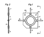
- Fig. 1 is a schematic view of the valve means according to a preferred embodiment,
- Fig. 2 is a view taken long line II-II in Fig. 1, and
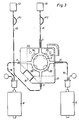
- Fig. 3 illustrates the use of said valve means in an outer flow system.
- As is shown in Fig. 1 a preferred valve means according to the invention thus comprises four individual connections 1-4 in communication with an annular substantially closed
channel 5 formed between two welded flat sheet 6 and 7 (Fig. 2). In the illustrated example two of said connections are intended to serve as inlets, such as 1 and 3, and two as outlets, such as 2 and 4. - The
inlets 1 and 3 and the outlets 2 and 4 are conveniently provided in pairs diametrically opposed to each other and may be constituted by short tube nipples welded between the flat sheets 6 and 7. - The
channel 5 needs not be endless, as is shown in Fig. 1 but can as well be in the form of an interrupted loop, such as a horseshoe with preferably two of said connections being provided at each end of said interrupted loop. - The flow system according to Fig. 3 may for example be a so-called extracorporeal system for treatment of blood, which is intended for example to remove specific antibodies from the blood with use of two parallelly coupled
adsorption columns 8 and 9 through which the blood is intended to flow for adsorption of such antibodies. - Conveniently the columns therefore comprise antigens which are immobilized on any suitable carrier and which are specifically directed against said antibodies. Such columns are previously known and need therefore not be described in detail herein. Instead it is referred to for example the Swedish Patent Application No. 8206520-2, filed November 16,1982, which describes such an adsorption column particularly intended to remove antibodies against factor IX from blood of a hemophilic patient.
- In the illustrated treating system (intended to remove for example such antibodies against factor IX from blood of a hemophilic patient) the first inlet 1 is in communication with a
source 10 for an eluting agent (rinsing liquid) via anouter connection 11, while theother inlet 3 in a similar way is in communication with anouter source 12 for blood, for example a patient, via anouter connection 13. Said first outlet 2 is in communication with a first adsorption column 8 via anouter connection 14 and the other outlet 4 is in communication with asecond column 9 via anouter connection 15. - Preferably the valve means is located behind a
door 17 which is openable and closable by means of for example ahinge 16 and which is mounted for example on the front panel of a monitoring unit which is forming a part of the treating system. Thechannel 5 can thereby be externally compressed by means of compressing organs 18-21 -(as schematically illustrated by broken circles in Fig. 3), which can be adapted to either alone or in pairs be directed to externally compress thechannel 5 to control liquid flows in a desired manner, as will be explained in the following in connection with the description of the operation of the valve means. - If, for example, the channel communications between the first inlet 1 and the first outlet 2 and between the
second inlet 3 and the second outlet 4, respectively, are kept closed by compression by means of theorgans 18 and 19, respectively, and if in a corresponding way the channel communications between thesecond inlet 3 and the first outlet 2 and the first inlet 1 and the second outlet 4, respectively, are kept open, the blood is thus pumped from thesource 12 by means of a pump P1 in theouter connection 13 into achannel 5 through thesecond outlet 3. From there the blood is pumped to the outlet 2 and reaches the first absorption column 8 via theouter connection 14 for adsorption of said antibodies. In a corresponding manner eluting liquid is thus pumped from thesource 10 by means of a pump P2 in theouter connection 11 into thechannel 5 through the first inlet 1 and further to thesecond column 9, which previously can be saturated on said antibodies, via the second outlet 4 and theouter connection 15 for regenerating of thesecond column 9. - When the first column 8 is saturated on antibodies the
compressing organs 18 and 20 open the respective channel communications at the same time as the compressingorgans 19 and 21 from outside clamp the channel communications between thesecond inlet 3 and the first outlet 2 and the first inlet 1 and the second outlet 4, respectively. In this position the blood is instead pumped via thesecond inlet 3 to thesecond column 9 via the second outlet 4 and theouter connection 15, while the eluting agent is pumped to the first column 8 via the first inlet 1 and the first outlet 2 and theouter connection 14. When thesecond column 9 is again saturated on antibodies the flow directions are again changed for the blood and the eluting agent by means of the compressing organs 18-21 as described above, whereby the alternating adsorption and regeneration is repeated. - As previously mentioned said compressing organs 18-21 need not be directed in pairs, but this can be directed independently from each other, whereby it is possible to direct the liquid flows optionally in an unlimited number of optional ways.
- According to the invention said flat sheets 6 and 7 may form part of a disposable tube set further comprising pumping segments for extracorporeal treatment of blood.
- As suggested in Figs. 1 and 3 (at 22) said flat sheets may comprise means for suspension against the
door 17, whereby the flat sheets preferably have an asymmetric outer shape intended to facilitate location of the flat sheets to thereby avoid a wrong use of these.
Claims (8)
Applications Claiming Priority (2)
| Application Number | Priority Date | Filing Date | Title |
|---|---|---|---|
| SE8400682A SE444709B (en) | 1984-02-09 | 1984-02-09 | VALVE DEVICE WITH INTERMEDIATE FLEXIBLE PLANFOLY IMAGED CHANNEL SYSTEM |
| SE8400682 | 1984-02-09 |
Publications (3)
| Publication Number | Publication Date |
|---|---|
| EP0156110A2 EP0156110A2 (en) | 1985-10-02 |
| EP0156110A3 EP0156110A3 (en) | 1986-12-03 |
| EP0156110B1 true EP0156110B1 (en) | 1989-10-18 |
Family
ID=20354665
Family Applications (1)
| Application Number | Title | Priority Date | Filing Date |
|---|---|---|---|
| EP19850100677 Expired EP0156110B1 (en) | 1984-02-09 | 1985-01-24 | Valve means |
Country Status (4)
| Country | Link |
|---|---|
| EP (1) | EP0156110B1 (en) |
| JP (1) | JPS60237275A (en) |
| DE (1) | DE3573727D1 (en) |
| SE (1) | SE444709B (en) |
Cited By (1)
| Publication number | Priority date | Publication date | Assignee | Title |
|---|---|---|---|---|
| US6017493A (en) * | 1997-09-26 | 2000-01-25 | Baxter International Inc. | Vacuum-assisted venous drainage reservoir for CPB systems |
Families Citing this family (4)
| Publication number | Priority date | Publication date | Assignee | Title |
|---|---|---|---|---|
| JPH0674849B2 (en) * | 1989-12-21 | 1994-09-21 | 竜 川辺 | Method and device for opening and closing multi-way valve |
| FR2682876A1 (en) * | 1991-10-23 | 1993-04-30 | Coletta Daniel | Stopcock device for infusion and fastening on any upright of a hospital bed |
| CN114001180B (en) * | 2022-01-04 | 2022-04-08 | 浙江金仪盛世生物工程有限公司 | Pinch valve head for switching and pinch valve group |
| CN114001181B (en) * | 2022-01-04 | 2022-04-08 | 浙江金仪盛世生物工程有限公司 | Pinch valve head and pinch valve group with same |
Family Cites Families (4)
| Publication number | Priority date | Publication date | Assignee | Title |
|---|---|---|---|---|
| US3697418A (en) * | 1971-01-25 | 1972-10-10 | Cci Aerospace Corp | Method and apparatus for regenerating the dialyzing fluid for an artificial kidney |
| US4425113A (en) * | 1982-06-21 | 1984-01-10 | Baxter Travenol Laboratories, Inc. | Flow control mechanism for a plasmaspheresis assembly or the like |
| US4428745A (en) * | 1982-06-21 | 1984-01-31 | Baxter Travenol Laboratories, Inc. | Flow control mechanism for a plasmapheresis assembly or the like |
| SE451946B (en) * | 1982-12-10 | 1987-11-09 | Gambro Lundia Ab | DEVICE FOR THE DISPOSAL OF ONE OR MORE FRACTIONS OF WHOLE BLOOD, PLASMA OR SIMILAR BODY WASHES |
-
1984
- 1984-02-09 SE SE8400682A patent/SE444709B/en not_active IP Right Cessation
-
1985
- 1985-01-24 DE DE8585100677T patent/DE3573727D1/en not_active Expired
- 1985-01-24 EP EP19850100677 patent/EP0156110B1/en not_active Expired
- 1985-02-07 JP JP2272985A patent/JPS60237275A/en active Pending
Cited By (1)
| Publication number | Priority date | Publication date | Assignee | Title |
|---|---|---|---|---|
| US6017493A (en) * | 1997-09-26 | 2000-01-25 | Baxter International Inc. | Vacuum-assisted venous drainage reservoir for CPB systems |
Also Published As
| Publication number | Publication date |
|---|---|
| EP0156110A3 (en) | 1986-12-03 |
| JPS60237275A (en) | 1985-11-26 |
| SE8400682D0 (en) | 1984-02-09 |
| SE8400682L (en) | 1985-08-10 |
| EP0156110A2 (en) | 1985-10-02 |
| SE444709B (en) | 1986-04-28 |
| DE3573727D1 (en) | 1989-11-23 |
Similar Documents
| Publication | Publication Date | Title |
|---|---|---|
| US6743201B1 (en) | Cassette for delivering fluids, especially dialysis fluids | |
| US7223338B2 (en) | Support element for an integrated module for blood treatment, an integrated module for blood treatment, and a manufacturing process for an integrated module for blood treatment | |
| CA2074698A1 (en) | Artificial kidney and a method of controlling it | |
| CA2204503A1 (en) | Peritoneal dialysis system with variable pressure drive | |
| US8747662B2 (en) | Modular hemofiltration apparatus with removable panels for multiple and alternate blood therapy | |
| DE69636816D1 (en) | CONNECTION CARTRIDGE | |
| CA2307302A1 (en) | Portable peristaltic pump for peritoneal dialysis | |
| WO1998017333A3 (en) | Continuous flow-through peritoneal dialysis (cfpd) method with control of intraperitoneal pressure | |
| EP0191071A1 (en) | Device for pumping liquids which are highly sensitive to mechanical strains. | |
| CA2272348A1 (en) | Integrated cassette for controlling fluid having an integral filter | |
| AU4159599A (en) | Dialysis machine, in particular for home use | |
| CA2115414A1 (en) | Technique for extracorporeal treatment of blood | |
| JPH09276398A (en) | Disposable balancing device for balancing various liquids for a medical handling device and a medical handling device having a plug-in unit containing such a disposable balancing device | |
| CA2459327A1 (en) | Implantable infusion device and reservoir for same | |
| CA2514974C (en) | A support element for an integrated module for blood treatment | |
| JPH09248335A (en) | Bendable filtering pouch | |
| EP0156110A2 (en) | Valve means | |
| EP1180375A1 (en) | Pulsating pumping unit for a fluid, particularly blood | |
| CN105457118B (en) | Apparatus for purifying blood and system | |
| KR20050098895A (en) | Support element for an integrated blood treatment module | |
| CA1256810A (en) | End plate and module for plasmapheresis | |
| AU2004210212A1 (en) | Integrated blood treatment module and extracorporeal blood treatment apparatus. | |
| CA2318316A1 (en) | An apparatus for use in connection with removal of elements, especially exogenous antibodies, from blood or plasma | |
| CA1252737A (en) | Plasmapheresis filtration module | |
| CA1197472A (en) | Plasmapheresis filtration module |
Legal Events
| Date | Code | Title | Description |
|---|---|---|---|
| PUAI | Public reference made under article 153(3) epc to a published international application that has entered the european phase |
Free format text: ORIGINAL CODE: 0009012 |
|
| AK | Designated contracting states |
Designated state(s): BE CH DE FR GB IT LI LU NL |
|
| PUAL | Search report despatched |
Free format text: ORIGINAL CODE: 0009013 |
|
| AK | Designated contracting states |
Kind code of ref document: A3 Designated state(s): BE CH DE FR GB IT LI LU NL |
|
| 17P | Request for examination filed |
Effective date: 19870317 |
|
| 17Q | First examination report despatched |
Effective date: 19881021 |
|
| GRAA | (expected) grant |
Free format text: ORIGINAL CODE: 0009210 |
|
| AK | Designated contracting states |
Kind code of ref document: B1 Designated state(s): BE CH DE FR GB IT LI LU NL |
|
| ITF | It: translation for a ep patent filed | ||
| REF | Corresponds to: |
Ref document number: 3573727 Country of ref document: DE Date of ref document: 19891123 |
|
| ET | Fr: translation filed | ||
| PG25 | Lapsed in a contracting state [announced via postgrant information from national office to epo] |
Ref country code: LU Free format text: LAPSE BECAUSE OF NON-PAYMENT OF DUE FEES Effective date: 19900131 |
|
| PGFP | Annual fee paid to national office [announced via postgrant information from national office to epo] |
Ref country code: NL Payment date: 19900131 Year of fee payment: 6 |
|
| PLBE | No opposition filed within time limit |
Free format text: ORIGINAL CODE: 0009261 |
|
| STAA | Information on the status of an ep patent application or granted ep patent |
Free format text: STATUS: NO OPPOSITION FILED WITHIN TIME LIMIT |
|
| 26N | No opposition filed | ||
| ITTA | It: last paid annual fee | ||
| PG25 | Lapsed in a contracting state [announced via postgrant information from national office to epo] |
Ref country code: NL Effective date: 19910801 |
|
| NLV4 | Nl: lapsed or anulled due to non-payment of the annual fee | ||
| PGFP | Annual fee paid to national office [announced via postgrant information from national office to epo] |
Ref country code: FR Payment date: 19921223 Year of fee payment: 9 |
|
| PGFP | Annual fee paid to national office [announced via postgrant information from national office to epo] |
Ref country code: GB Payment date: 19930118 Year of fee payment: 9 |
|
| PGFP | Annual fee paid to national office [announced via postgrant information from national office to epo] |
Ref country code: CH Payment date: 19930129 Year of fee payment: 9 |
|
| PGFP | Annual fee paid to national office [announced via postgrant information from national office to epo] |
Ref country code: BE Payment date: 19930201 Year of fee payment: 9 |
|
| PG25 | Lapsed in a contracting state [announced via postgrant information from national office to epo] |
Ref country code: GB Effective date: 19940124 |
|
| PG25 | Lapsed in a contracting state [announced via postgrant information from national office to epo] |
Ref country code: LI Effective date: 19940131 Ref country code: CH Effective date: 19940131 Ref country code: BE Effective date: 19940131 |
|
| BERE | Be: lapsed |
Owner name: GAMBRO LUNDIA A.B. Effective date: 19940131 |
|
| GBPC | Gb: european patent ceased through non-payment of renewal fee |
Effective date: 19940124 |
|
| PG25 | Lapsed in a contracting state [announced via postgrant information from national office to epo] |
Ref country code: FR Effective date: 19940930 |
|
| REG | Reference to a national code |
Ref country code: CH Ref legal event code: PL |
|
| REG | Reference to a national code |
Ref country code: FR Ref legal event code: ST |
|
| PGFP | Annual fee paid to national office [announced via postgrant information from national office to epo] |
Ref country code: DE Payment date: 20040205 Year of fee payment: 20 |