EP0155986A2 - Pipette puller - Google Patents
Pipette puller Download PDFInfo
- Publication number
- EP0155986A2 EP0155986A2 EP84109559A EP84109559A EP0155986A2 EP 0155986 A2 EP0155986 A2 EP 0155986A2 EP 84109559 A EP84109559 A EP 84109559A EP 84109559 A EP84109559 A EP 84109559A EP 0155986 A2 EP0155986 A2 EP 0155986A2
- Authority
- EP
- European Patent Office
- Prior art keywords
- heating elements
- heating
- binding post
- tubing
- movable clamp
- Prior art date
- Legal status (The legal status is an assumption and is not a legal conclusion. Google has not performed a legal analysis and makes no representation as to the accuracy of the status listed.)
- Withdrawn
Links
Images

Classifications
-
- C—CHEMISTRY; METALLURGY
- C03—GLASS; MINERAL OR SLAG WOOL
- C03B—MANUFACTURE, SHAPING, OR SUPPLEMENTARY PROCESSES
- C03B23/00—Re-forming shaped glass
- C03B23/04—Re-forming tubes or rods
- C03B23/047—Re-forming tubes or rods by drawing
- C03B23/0473—Re-forming tubes or rods by drawing for forming constrictions
Definitions
- Binding post means referred to generally as 80 comprise four posts 81, 82, 83 and 84 which utilize clips 81a, 82a, 83a and 84a anchored by set screws 81b, 82b, 83b and 84b to support the ends of heating elements 61 and 62.
Landscapes
- Chemical & Material Sciences (AREA)
- Engineering & Computer Science (AREA)
- Materials Engineering (AREA)
- Organic Chemistry (AREA)
- Devices For Use In Laboratory Experiments (AREA)
- Sampling And Sample Adjustment (AREA)
- Physical Or Chemical Processes And Apparatus (AREA)
Abstract
A pipette puller is provided for drawing glass or quartz tubing into micropipettes. A fixed clamp and movable clamp are utilized and between the clamps a furnace is provided which has an opposing pair of elongated heating elements. The heating elements are supported by binding posts of high thermal conductivity and relatively large mass, which provides relatively low thermal inertia of the heating elements. The heating elements may be moved relative to each other, facilitating a high degree of control ofthetemperature applied to the glass or quartz tubing for obtaining uniformly repeatable shapes of micropipettes.
Description
- The present invention relates to the field of drawing glass or quartz tubing into micropipettes which may be utilized as microelectrodes, needles or the like.
- The prior art teaches a variety of pipette pullers and glass drawing instruments. A book entitled "Physical techniques in Biological Research, Vol. 5," published in 1967 and edited by William Nastuck, describes a variety of prior art devices for pulling glass pipettes for use as microelectrodes. The heating elements described are generally platinum coils, tubular heaters or elements which subtend an angle around the heating zone of more than 270°. U.S. Patent 4,111,677 dated September 5, 1978 shows a device utilizing dual furnaces in which each furnace utilizes coil heaters. Generally speaking, the heating elements of the prior art have relatively high thermal inertia, relatively poor temperature control of heating elements and are not capable of adjusting the relative positions of the glass tube and the heating elements.
- The present invention provides a pipette puller apparatus for drawing glass or quartz tubing into micropipettes comprising:
- a first clamp,
- a movable clamp means,
- furnace means positioned between said clamps, said furnace means comprising an opposing pair of elongated heating elements, a heating zone defined between the central portions of said heating elements, and binding post means with high thermal conductivity which support the ends of said heating elements.
- The objects, features and advantages of the present invention will be readily apparent from the following description taken in cojunction with the accompanying drawings in which:
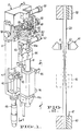
- Fig. 1 is a perspective view of the pipette puller;
- Fig. 2 is a schematic representation of the process of drawing a piece of tubing;
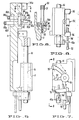
- Fig. 3 is an elevational view of a portion of the mechanism shown in Fig. 1;
- Fig. 4 is a cross-sectional view taken substantially along the line 4-4 of Fig. 3;
- Fig. 5 is a cross-sectional view taken along the line 5-5 of Fig. 1;
- Fig. 6 is a cross-sectional view taken along the line 6-6 of Fig. 5;
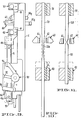
- Fig. 7 is an elevational view along the line 7-7 of Fig. 1;
- Fig 8 is an elevational view along the line 8-8 of Fig. 7;
- Fig. 9 is an elevational view of the apparatus;
- Fig. 10 is a schematic representation of a portion of the patch clamp drawing process; and
- Fig. 11 is a schematic representation of another pipette design that can be produced with the apparatus.
- Fig. 1 shows the pipette puller shown generally as 10 for drawing glass or
quartz tubing 20 into micropipettes, microelectrodes or microneedles in which the tip will be open and typically less than one micron in outer diameter. Two micropipettes are formed from tube 20 (Fig. 2). As used herein the term "micropipette" includes microelectrodes and microneedles with tips of ten microns or less outer diameter. - Fixed
clamp 30 holds the upper end oftubing 20 during the drawing process. Movable second clamp means 40 grasps the lower section oftubing 20 and moves in a downwardly direction as shown byarrow 47 of Fig. 2 when the drawing temperature has been attained. Furnace means shown generally as 60 heats the tubing to a precise temperature at a precisely controlled rate to increase the repeatability of the drawing process. As shown best in Fig. 4, furnace means 60 comprises an opposing pair ofelongated heating elements elements posts clips set screws heating elements -
Heating elements heating elements heating element heating elements tubing 20. Asheating elements tubing 20, thereby facilitating removal oftubing 20 and loading a new section of tubing. Although it is possible to bend either or bothheating elements 61 and/or 62 so that the element forms a concave surface relative to heating zone 25, those orientations are not as desirable as that shown in Fig. 4. I have found that using the orientation ofheating elements surrounds tubing 20. I believe the uniform temperature distribution aroundtubing 20 is facilitated in part by radiant heat reflecting offelements regions tube 20. - Binding posts 81-84 have
rectangular recesses heating elements - The mass of the binding posts exceeds the mass of the heating elements by roughly a factor of 250, in order to rapidly dissipate any excess heat in
elements heating elements - Slidably mounted support means are shown generally as 50 in Fig. 1 which carry binding post means 80. As shown best in Figs. 3 and 4, slidably mounted
support 51 carriesbinding posts heating element 61. Similarly,support 52 carriesbinding posts heating element 62. Springs 53 urge supports 51 and 52 apart while threadedscrews ears frame 11 of pipette puller 10.Thumb screws supports heating elements heating elements Heating elements - Bolt 81d threads into
sleeve 81f and connects bindingpost 81 to support 51 and bolt 83d threads into sleeve 83f and connects bindingpost 83 to support 51 as shown in Fig. 3. Similarly bolts 82d and 84d thread intosleeves posts Sleeves screws Sleeves 83f and 84f are connected electrically byconnection 83e secured byscrews 83g and 84g.Supports -
passageway 14 formed inframe 11 extends in the direction of heating zone 25 so that cooling air may be introduced in the direction ofarrow 15 in the event air is needed to reduce the temperature in heating zone 25. The airflow approaches heating zone 25 along a path extending betweenheating elements - Referring to Fig. 1, movable clamp means 40 comprises a
cylindrical slide 41 which is carried inpassageway 16 formed in frame 11 (Fig. 5).Optical switch 42 is activated byflag 43 which is carried byslide 41 throughconnector 44 andshaft 45. As the drawing temperature of the tubing is reached, the dead weight of movable clamp means 40 applies a gentle downward force andflag 43 moves downwardly relative tooptical switch 42 which immediately shuts off the power to heatingelements slide 41 may be driven by a solenoid or other means to accomplish a predetermined rate and amount of downward force which produces a variety of shapes of the tubing. - The position of
optical switch 42 is controlled bymicrometer thumb wheel 49. - It is often advantageous to draw the tubing in multiple stages, referred to herein as the patch clamp mode. In the patch clamp mode, it is important that the initial pull be consistent and repeatable so that multiple micropipettes can be formed with the most uniform characteristics of shank tip and lumen characteristics. Patch clamp means 90 shown best in Fig. 7 is provided for this purpose. Patch clamp means 90 includes
arms indicator arm 92, and stops 93 and 94. First stop 93 as shown in Fig. 7 is in its retracted position. As shown in phantom in Fig. 7, stop 93 is in position to limit the downward travel ofslide 41. Asecond stop 94 is provided which in the position shown in Fig. 7 restricts the upward motion ofslide 41 by impinging uponpin 41a which is rigidly attached to slide 41 as shown in Fig. 1. To operate the device in the patch clamp mode, patch clamp means 90 is first put into its position as shown in Fig. 9 and in phantom in Fig. 7.Tubing 20 is heated and drawn distance "d" as shown in Fig. 10, at which point stop 93 limits the downward travel ofslide 41.Tubing 20 is drawn into a shape as generally shown in Fig. 10. Patch clamp means 90 is then moved into the position shown in Fig. 7, the fixedclamp 30 is opened and slide 41 is moved upwardly until pin 4la hitspatch clamp stop 94.Upper clamp 30 is tightened andheating elements narrow portion 20a oftubing 20. Patch clamp means 90 is then moved to a neutral position between the two positions shown in Fig. 7 and the second pull is made.Upper arm 95 andlower arm 96 of patch clamp means 90 serve an indicating function of the position of patch clamp means 90 and provide an easy means of moving patch clamp means 90 to any of its three positions in each of which it is maintained by a spring detent. - Fig 11 shows how the use of alternate temperatures and drawing force will produce two
micropipettes 120, 121 (shown prior to separation) of relatively shorter length of tip. - Fig. 6 shows the construction of
clamp 30. A similar construction is used for movable clamp 4a.Knob 31 drives threadedscrew 32 into a threadedpssageway 33 inframe 11. A resilient and heatresistant pad 34 moves with respect to a V-shapedseat 35 formed inframe 11.Tubing 20 is held betweenseat 35 andpad 34 and may be readily removed from theclamp 30 asresilient pad 34 is moved outwardly fromseat 35. When clamps 30 and 40a are open,tube 20 can be readily inserted into or removed from the puller 10. - In operation, I have been able to draw quartz tubing as well as borosilicate glass and to obtain repeatable results with open tips substantially less than one micron outer diameter. I believe that this invention is the first mechanism capable of repeatably drawing quartz tubing. The use of
heating elements tubing 20 facilitates extremely delicate regulation of the temperatures applied to thetubing 20.
Claims (9)
1. A pipette puller apparatus for drawing glass or quartz tubing into micropipetes comprising;
a first clamp,
a movable clamp means,
furnace means positioned between said clamps, said furnace means comprising an opposing pair of elongated heating elements, a heating zone defined between the central portions of said heating zone defined between the central portions of said heating elements, and binding post means with high thermal conductivity which support the ends of said heating elements.
2. The apparatus of claim 1, including slidably mounted support means which carry said binding post means whereby either of said heating elements can be moved relative to the other.
3. The apparatus of claim 1 or 2, wherein the mass of said binding post means exceeds the mass of said heating elements by at least a factor of fifty so that the thermal inertia of said heating elements is low.
4. The apparatus of claim 1, 2 or 3, wherein each of said heating elements forms a convex surface relative to said heating zone.
5. The apparatus of claim 4, wherein said heating elements are rectangular in cross-section and the height exceeds the thickness by a factor of at least ten.
6. The apparatus of claim 5, wherein each of said binding post Teans has a rectangular recess which receives and surrounds one end of said heating element.
7. The apparatus of any one of the preceding claims, including air injector means for introducing airflow into said heating zone along a path extending between said heating elements.
8. The apparatus of any one of the preceding claims, wherein said movable clamp means comprises a slide which carries said movable clamp means and patching clamp means for limiting the motion of said movable clamp means.
9. The apparatus of any one of the preceding claims, wherein said heating elements are adjustable at operating temperatures.
Applications Claiming Priority (2)
| Application Number | Priority Date | Filing Date | Title |
|---|---|---|---|
| US06/593,261 US4530712A (en) | 1984-03-26 | 1984-03-26 | Pipette puller |
| US593261 | 1984-03-26 |
Publications (2)
| Publication Number | Publication Date |
|---|---|
| EP0155986A2 true EP0155986A2 (en) | 1985-10-02 |
| EP0155986A3 EP0155986A3 (en) | 1986-10-22 |
Family
ID=24374046
Family Applications (1)
| Application Number | Title | Priority Date | Filing Date |
|---|---|---|---|
| EP84109559A Withdrawn EP0155986A3 (en) | 1984-03-26 | 1984-08-10 | Pipette puller |
Country Status (2)
| Country | Link |
|---|---|
| US (1) | US4530712A (en) |
| EP (1) | EP0155986A3 (en) |
Families Citing this family (13)
| Publication number | Priority date | Publication date | Assignee | Title |
|---|---|---|---|---|
| US4600424A (en) * | 1985-03-21 | 1986-07-15 | Flaming Dale G | Method of forming an ultrafine micropipette |
| US4869745A (en) * | 1989-04-24 | 1989-09-26 | Flaming Dale G | Apparatus for forming micropipette of controlled configuration by moving the point of heat application |
| US4921522A (en) * | 1989-04-24 | 1990-05-01 | Flaming Dale G | Method and apparatus for forming a micropipette with uniform application of heat |
| US5185922A (en) * | 1990-08-17 | 1993-02-16 | Cornell Research Foundation, Inc. | Method of making submicrometer microelectrodes |
| US5370843A (en) * | 1993-09-13 | 1994-12-06 | Asi Instruments, Inc. | Pipette puller |
| US5792110A (en) * | 1996-06-26 | 1998-08-11 | Cunningham; Miles G. | Systems and methods for delivering therapeutic agents to selected sites in a subject |
| US6391149B1 (en) * | 1998-06-04 | 2002-05-21 | Advanced Cardiovascular Systems, Inc. | Method and apparatus for concentrating a solute in solution with a solvent |
| US6079230A (en) * | 1999-02-02 | 2000-06-27 | Kong; Jian-Qiang | Apparatus for preparing quartz micropipettes |
| US6363750B1 (en) | 2000-02-25 | 2002-04-02 | Chris D. Chiodo | Automatic pipette puller and forge |
| US20040142572A1 (en) * | 2003-01-16 | 2004-07-22 | Deveau Jason S. T. | Apparatus and method for selectively inducing hydrophobicity in a single barrel of a multibarrel ion selective microelectrode |
| US8540911B2 (en) * | 2010-11-16 | 2013-09-24 | Miniplast Ein-Shemer ACS Ltd. | Methods of manufacturing polymer pipettes |
| CN106000496B (en) * | 2016-06-07 | 2017-10-17 | 中国农业科学院油料作物研究所 | A kind of preparation method and application of glass micro suction dispenser |
| CN117003482B (en) * | 2023-10-08 | 2023-12-19 | 成都泰盟软件有限公司 | Vertical drawing instrument for multi-step drawing |
Citations (3)
| Publication number | Priority date | Publication date | Assignee | Title |
|---|---|---|---|---|
| US2265359A (en) * | 1936-06-20 | 1941-12-09 | Gen Electric | Process and apparatus for sealingoff vessels containing gas |
| US3556758A (en) * | 1965-10-22 | 1971-01-19 | Gen Electric | Method for making an electrolyte guide member |
| US4111677A (en) * | 1975-01-24 | 1978-09-05 | Trw Inc. | Apparatus for drawing glass tubing |
Family Cites Families (6)
| Publication number | Priority date | Publication date | Assignee | Title |
|---|---|---|---|---|
| DK117798B (en) * | 1963-12-06 | 1970-06-01 | O Buus | Contraction pipette. |
| US3556760A (en) * | 1968-06-28 | 1971-01-19 | Virtis Co Inc | Apparatus for heat sealing evacuated glass ampules |
| US4121920A (en) * | 1970-04-06 | 1978-10-24 | International Telephone & Telegraph Corp. | Glass fiber drawing machine |
| US3652248A (en) * | 1970-06-09 | 1972-03-28 | Edward J Mellen Jr | Process for redrawing silica glass rods |
| DE2234061C3 (en) * | 1972-07-07 | 1979-11-29 | Hans-Joachim 1000 Berlin Dichter | Method and device for the production of ampoules, with funnel-shaped spike ends |
| US3985535A (en) * | 1975-06-19 | 1976-10-12 | Smithkline Corporation | Method of making glass ampul for jet injector |
-
1984
- 1984-03-26 US US06/593,261 patent/US4530712A/en not_active Expired - Fee Related
- 1984-08-10 EP EP84109559A patent/EP0155986A3/en not_active Withdrawn
Patent Citations (3)
| Publication number | Priority date | Publication date | Assignee | Title |
|---|---|---|---|---|
| US2265359A (en) * | 1936-06-20 | 1941-12-09 | Gen Electric | Process and apparatus for sealingoff vessels containing gas |
| US3556758A (en) * | 1965-10-22 | 1971-01-19 | Gen Electric | Method for making an electrolyte guide member |
| US4111677A (en) * | 1975-01-24 | 1978-09-05 | Trw Inc. | Apparatus for drawing glass tubing |
Also Published As
| Publication number | Publication date |
|---|---|
| US4530712A (en) | 1985-07-23 |
| EP0155986A3 (en) | 1986-10-22 |
Similar Documents
| Publication | Publication Date | Title |
|---|---|---|
| US4530712A (en) | Pipette puller | |
| JP2721346B2 (en) | Forming optical fiber connections | |
| US20090308106A1 (en) | Electric furnace extension method and extension apparatus for optical fiber glass preform | |
| US4600424A (en) | Method of forming an ultrafine micropipette | |
| CN1062786A (en) | Probe for extensometer | |
| US4743730A (en) | Device for straightening and cutting metallic wire | |
| US5181948A (en) | Method and apparatus for forming micropipette of controlled configuration | |
| US6220057B1 (en) | Apparatus and method for drawing a glass ingot | |
| EP1007485A1 (en) | Improved method of drawing a waveguide preform | |
| US4818266A (en) | Apparatus for producing glass tubing of a narrowed diameter | |
| US5288301A (en) | Method for fabrication of fused fibre devices | |
| US4869745A (en) | Apparatus for forming micropipette of controlled configuration by moving the point of heat application | |
| JPS6027377A (en) | Method and apparatus for manufacturing thin capillary tube | |
| Kirk et al. | Reproducible construction of quartz fiber devices | |
| TW200521097A (en) | Method for drawing optical fiber base material | |
| JP3151386B2 (en) | Manufacturing method of optical fiber preform | |
| CN219136653U (en) | Drawing mechanism for glass capillary needle point | |
| US5346521A (en) | Apparatus and method for fabricating optical fiber coupler | |
| RU2024440C1 (en) | Method and apparatus for manufacturing of micropipettes | |
| JP3864463B2 (en) | Stretching method | |
| US1987734A (en) | Method and apparatus for working glass | |
| Bertrand et al. | Fabrication of glass microelectrodes with microprocessor control | |
| JPS569231A (en) | Manufacture of glass rod or pipe | |
| JP6136554B2 (en) | Glass base material stretching apparatus and glass base material manufacturing method | |
| CN111499165A (en) | Device for manufacturing planar snake-shaped glass micro-channel |
Legal Events
| Date | Code | Title | Description |
|---|---|---|---|
| PUAI | Public reference made under article 153(3) epc to a published international application that has entered the european phase |
Free format text: ORIGINAL CODE: 0009012 |
|
| AK | Designated contracting states |
Designated state(s): AT BE CH DE FR GB IT LI LU NL SE |
|
| PUAL | Search report despatched |
Free format text: ORIGINAL CODE: 0009013 |
|
| AK | Designated contracting states |
Kind code of ref document: A3 Designated state(s): AT BE CH DE FR GB IT LI LU NL SE |
|
| STAA | Information on the status of an ep patent application or granted ep patent |
Free format text: STATUS: THE APPLICATION IS DEEMED TO BE WITHDRAWN |
|
| 18D | Application deemed to be withdrawn |
Effective date: 19870623 |