EP0155887B1 - Structural cover-doors participating in the total rigidity of a turbojet engine - Google Patents
Structural cover-doors participating in the total rigidity of a turbojet engine Download PDFInfo
- Publication number
- EP0155887B1 EP0155887B1 EP85400427A EP85400427A EP0155887B1 EP 0155887 B1 EP0155887 B1 EP 0155887B1 EP 85400427 A EP85400427 A EP 85400427A EP 85400427 A EP85400427 A EP 85400427A EP 0155887 B1 EP0155887 B1 EP 0155887B1
- Authority
- EP
- European Patent Office
- Prior art keywords
- assembly according
- cover member
- cover assembly
- structural
- structural cover
- Prior art date
- Legal status (The legal status is an assumption and is not a legal conclusion. Google has not performed a legal analysis and makes no representation as to the accuracy of the status listed.)
- Expired
Links
Images


Classifications
-
- B—PERFORMING OPERATIONS; TRANSPORTING
- B64—AIRCRAFT; AVIATION; COSMONAUTICS
- B64D—EQUIPMENT FOR FITTING IN OR TO AIRCRAFT; FLIGHT SUITS; PARACHUTES; ARRANGEMENTS OR MOUNTING OF POWER PLANTS OR PROPULSION TRANSMISSIONS IN AIRCRAFT
- B64D29/00—Power-plant nacelles, fairings, or cowlings
- B64D29/08—Inspection panels for power plants
-
- F—MECHANICAL ENGINEERING; LIGHTING; HEATING; WEAPONS; BLASTING
- F02—COMBUSTION ENGINES; HOT-GAS OR COMBUSTION-PRODUCT ENGINE PLANTS
- F02C—GAS-TURBINE PLANTS; AIR INTAKES FOR JET-PROPULSION PLANTS; CONTROLLING FUEL SUPPLY IN AIR-BREATHING JET-PROPULSION PLANTS
- F02C7/00—Features, components parts, details or accessories, not provided for in, or of interest apart form groups F02C1/00 - F02C6/00; Air intakes for jet-propulsion plants
- F02C7/20—Mounting or supporting of plant; Accommodating heat expansion or creep
-
- F—MECHANICAL ENGINEERING; LIGHTING; HEATING; WEAPONS; BLASTING
- F02—COMBUSTION ENGINES; HOT-GAS OR COMBUSTION-PRODUCT ENGINE PLANTS
- F02K—JET-PROPULSION PLANTS
- F02K3/00—Plants including a gas turbine driving a compressor or a ducted fan
- F02K3/02—Plants including a gas turbine driving a compressor or a ducted fan in which part of the working fluid by-passes the turbine and combustion chamber
- F02K3/04—Plants including a gas turbine driving a compressor or a ducted fan in which part of the working fluid by-passes the turbine and combustion chamber the plant including ducted fans, i.e. fans with high volume, low pressure outputs, for augmenting the jet thrust, e.g. of double-flow type
- F02K3/06—Plants including a gas turbine driving a compressor or a ducted fan in which part of the working fluid by-passes the turbine and combustion chamber the plant including ducted fans, i.e. fans with high volume, low pressure outputs, for augmenting the jet thrust, e.g. of double-flow type with front fan
Definitions
- the invention relates to cowlings which contribute to the overall rigidity of a turbofan engine with separate flow, comprising a structural cowl fixed between a front flange and a rear flange of the crankcase.
- the structural cowling is formed by two semi-cylindrical half cowls comprising radial members and longitudinal struts.
- the front edges of the half-covers are provided with a radial tongue of V-shaped section, directed towards the center.
- the front ferrule carries an annular groove with a profile complementary to that of the tongue.
- the rear edges of the half cowlings carry a profile designed to fit on the periphery of the rear support ring.
- the half cowlings are articulated by their upper longitudinal edges to a structure plate and are connected by jacks which allow, when latches, placed on the lower longitudinal edges of the half cowlings, are closed, to apply traction on the two half cowlings and thus ensure a positive tightening on the front and rear attachments. This gives a high rigidity rollover which takes up the forces to which the casing is subjected.
- the structural cowling as described has enabled a substantial reduction in the mechanical deformation of the casing, it is not the same for the deformation due to the temperature.
- the temperatures along the casing are very different from those taken by the cowling and, as a result of the longitudinal clamping of the casing, the longitudinal deformation although of small amplitude nevertheless produces significant forces which limit the efficiency of the device.
- the object of the invention is to provide a structural rollover of a type similar to that described above but comprising means eliminating the drawbacks due to the thermal expansion of the engine, ensuring aerodynamic continuity of the flow and sealing while allowing easy access. the engine fitted and possibly meeting the constraints of a thrust reverser on the blower.
- the device according to the invention is remarkable in that at least one expansion fixing device, allowing thermal expansion of the crankcase is provided between the inner structural cowling and one of the flanges of the crankcase.
- the fixing device comprises a sliding means allowing free expansion. longitudinal differential between casing and cover.
- the fixing device comprises a means of connection to the casing constituted by a device with at least three regularly spaced connecting pins, one end of the pins being fixed in a support of the motor housing, the other end cooperating with the bore of a spherical body held in a bearing fixed to the motor housing.
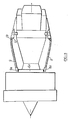
- FIG. 1 shows a schematic section of a turbofan engine with double flow and separate flows, mounted in a nacelle under the wings of an aircraft.
- the engine held in its casing 1, is extended forward by a fan 2, the casing of which is fixed to the crankcase, in known manner, by spacers 3.
- the engine is suspended from the pylon 4 by known devices such as screws, lugs, or other fixing means which will be specified later.
- the fan casing has an outer fairing 5 extending rearward over at least part of the engine casing. This fairing determines a passage for the flow of dilution air coming from the blower.
- the external fairing is crossed at least partially by the pylon 4.
- a cowling 7 between the front flange 6 for fixing the engine and nozzle inlet there is provided. The cowling covers the part of the engine corresponding approximately to the high pressure compressor, the combustion chambers, the outlet turbine and the nozzle inlet.
- the cowling 7 is reinforced so as to contribute to the rigidity of the engine casing.
- the cowling is formed of two approximately half-cylindrical shells 8, 9 internally reinforced by radial and longitudinal members ( Figures 3,4).
- the shells 8 and 9 are articulated on an upper tension plate 10 by their upper longitudinal edges.
- This plate is traversed by the engine suspension means constituted by a part of the pylon 4.
- the interior longitudinal edges carry latches allowing their attachment.
- Cylinders not shown ensure the opening of the cowling in the event of intervention on the engine and the tightening of the shells against the front fixing flanges 6 and rear 11 provided on the motor housing. The tightening allows the transmission of the forces from the crankcase to the rigid assembly formed by the shells 8 and 9 forming the internal cowling 7.
- the front fixing flange 6 comprises a cylindrical ferrule 6A on which the internal cylindrical bearings 8A and 9A come radially tighten before the shells 8 and 9.
- the rear fixing flange 11 has on its circumference a groove with a triangular section 12 in which is radially tightened and axially blocked a radial tooth 13 provided at the rear end and inside the shells.
- the tension plate is itself floating bearing upstream and downstream on the ferrule 6A and the flange 11.
- crankcase is likely to expand axially without undergoing significant stresses and, consequently, deformations.
- This ring 14 is connected, in known manner, to the pylon 4 by a link system as shown in FIG. 2 for the suspension of the rear part of the engine.
- the device with a radial pin comprises a ball joint 16 whose bearing 17 is fixed to the casing.
- the spherical body 18 is mounted on one end of the spindle 19. The other end being fixed in the support ring 14.
- the end of the spindle cooperating with the spherical body is,. possibly capable of sliding in a bore of the spherical body.
- the front linkage of the cowling it is provided for fixing by devices with an axial pin (FIG. 6).
- the front flange 6 is provided with axial pins 20 which are capable of sliding in the cylindrical part 21 provided in the spherical body 22 of a ball joint held in a circular frame 23.
- This coupling allows positive fixing of the cowling on the frame which can be of any known type, for example, bolting, U-clamp, quick-release flange tightening. Each opening of the cowling therefore does not risk deforming the sliding part or disturbing the sliding conditions.
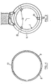
- a coupling is made (FIG. 7) between the flange 6 and the edge of the cowling made up of two coaxial rings 24, 25 arranged one in the other and cooperating by means of grooves 26 and teeth 27 disposed on their opposite faces, adjusted peripherally and leaving between them a radial clearance.
- the surfaces cooperating in the transmission of forces are of sufficient dimensions to reduce friction and can possibly be taken up with play.
- Such a fixing must include at least three teeth, a larger number can be chosen according to the forces to be absorbed. As the forces are greater in radial planes close to the horizontal, this can be taken into account not only in the number but also in the thickness of the horizontal "teeth" relative to the vertical "teeth”.
- the cowling is fixed to the outer ring 24 by removable means allowing the cowling to be clamped on the ring 24.
- the structural cowling 8, 9 has been provided in two parts and means allow the lifting of the shells, but this "inside” cowling is covered at least in part by the "exterior” cover 5 of the fan.
- This cowling is formed, at least in its rear part corresponding to the internal cowling, of two shells 28, 29 held at their upper part by articulations 30 fixed, for example on the pylon, and closed at their lower part in a known manner by locks (not shown).
- the shells 8, 9 forming the inner cover and the shells 28 and 29 forming the outer cover are hinged separately and can be opened in the same way.
- the shells of the outer cowling carry on their inner surface longitudinal wings 31, 32 directed inward, of sufficient height to come to cooperate with a seal 33, 34 carried by a flange 35, 36 of the shells of the inner cowling, and ensure the sealing of the secondary flow channel.
- This type of rollover is called type C rollover.
- the internal and external rollovers being independent, the loads to which the first is subjected are not transmitted to the second.
- the cylinders 43 are fixed on an intermediate plate 46. They are arranged at the front and at the rear of the plate. Although it is desirable that these jacks are aligned two by two in order to allow them to act in the same plane for the front respectively rear looping, the problems of space requirement can lead to a disposition where they are juxtaposed as in FIG. 11
- the plate is fixed by bolting or any other means at the front on the housing or the housing flange 6 and at the rear on the support ring 14.
- FIG. 12A shows in half-section a turbojet with flow reverser on the secondary air, the reverser being inactive.
- Figure 12B shows the same inverter in the active position.
- the thrust reverser provided in the cowling of the blower comprises, as known, reversing grids 47 arranged in the thickness of the nacelle, covered when a mobile section 48 of cowling is not used .
- the section 48 is translated rearward to release the grids. This maneuver leads to the establishment of the sealing means 49 of the secondary stream behind the grids, which has the effect of causing all the air flow coming from the fan to flow back forward.
- the section 48 is kept in its translational movement by a guide device 50 which can be of the type described in French patent n ° 2 496 533 and illustrated in FIG. 14. These devices are provided in sufficient number to allow the translation and maintenance of the movable section 48.
- Figures 13A and 13B show a type D cowling similar to that of Figures 10A and 10B with application of the solution of the intermediate plate ( Figure 11), and show the reversing device.
- the guiding devices 50 are arranged between the side walls 39A, 39B, 40A, 40B and the sections 48A, 48B of the shells 37, 38.
- These devices consist ( Figure 14) of a guide rail 51 having a cylindrical groove, fixed on the element frame 52 extending the side wall 39 or 41.
- a cylindrical tubular body 53 comprising, according to a generatrix, a wing 54, the end of which is fixed by any known means on the lateral edge of the rollover section.
- a fur 55 made of a material having good sliding characteristics and resistance to wear, is interposed between the rail and the cylindrical tubular body.
- the framework element 52 laterally carries two wings 56, 57 forming a groove a U in which the guide rail 51 is fixed by two parallel wings 58, 59.
- the movable section 48 is formed like the external cowling of two shells 48A and 48B which are fixed to the upper transverse walls 39A, 39B and lower 40A and 40B by the guide devices 50.
- the cowling can open under the action of the cylinders 43, fixed on the support plate 46, held between the front flange and the rear ring of the crankcase 1, acting on the internal structural cowling 8, 9.
- the lower edges of the two parts of cowling 8, 9 carry, as previously described, the latches 45 ensuring their connection.
Description
L'invention concerne des capotages participant à la rigidité d'ensemble d'un turboréacteur à double flux à flux séparés, comportant un capotage structural fixé entre une bride avant et une bride arrière du carter moteur.The invention relates to cowlings which contribute to the overall rigidity of a turbofan engine with separate flow, comprising a structural cowl fixed between a front flange and a rear flange of the crankcase.
L'augmentation du coût du carburant à incité les motoristes à améliorer l'efficacité des moteurs et pour ce à supprimer des défauts qui précédemment apparaissaient comme d'importance secondaire.The increased cost of fuel has prompted engine manufacturers to improve engine efficiency and thereby remove faults that previously appeared to be of secondary importance.
Ainsi leur attention s'est portée sur les faibles déformations se produisant dans la zone primaire du moteur et dues aux sollicitations de flexion. Ces flexions ont pour résultat d'augmenter le jeu en bout d'aubages et ainsi de diminuer l'efficacité du moteur.Thus their attention was focused on the small deformations occurring in the primary area of the engine and due to bending stresses. These flexions have the result of increasing the clearance at the end of the blades and thus reducing the efficiency of the engine.
Par suite de la forme en "taille de guêpe" du moteur, le seul renforcement du carter n'aurait presque abouti qu'à une augmentation de poids, sans apporter les résultats escomptés. Une solution à ce problème a été décrite dans l'article "Structural load carrying engine cowls" de K.W. Porter paru dans les pages 54, 55 du numéro d'octobre 1981 de la revue "Astronautic and Aeronautics", ce dispositif connu correspondant aux caractéristiques selon le préambule de la revendication 1. Le carter moteur renfermant le moteur est maintenu à l'avant dans une virole fixée au carter de soufflante et à l'arrière dans un anneau support. La virole et l'anneau sont supportés directement ou indirectement par le pylône.Owing to the wasp-shaped shape of the engine, the only strengthening of the casing would almost have resulted in an increase in weight, without bringing the expected results. A solution to this problem has been described in the article "Structural load carrying engine cowls" by KW Porter published in
Le capotage structural est formé de deux demi capotages semi cylindriques comportant des membrures radiales et des entretoises longitudinales.The structural cowling is formed by two semi-cylindrical half cowls comprising radial members and longitudinal struts.
Les bords avant des demi-capotages sont munis d'une languette radiale de section en V, dirigée vers le centre. La virole avant porte une rainure annulaire de profil complémentaire de celle de la languette.The front edges of the half-covers are provided with a radial tongue of V-shaped section, directed towards the center. The front ferrule carries an annular groove with a profile complementary to that of the tongue.
Les bords arrière des demi capotages portent un profilé prévu pour s'adapter sur la périphérie de l'anneau support arrière. Les demi capotages sont articulés par leurs bords longitudinaux supérieurs à une plaque de structure et sont reliés par des vérins qui permettent, lorsque des verrous, placés sur les bords longitudinaux inférieurs des demi capotages, sont fermés, d'appliquer une traction sur les deux demi capotages et d'assurer ainsi un serrage positif sur les fixations avant et arrière. On obtient ainsi un capotage de grande rigidité qui reprend les efforts auquel le carter est soumis.The rear edges of the half cowlings carry a profile designed to fit on the periphery of the rear support ring. The half cowlings are articulated by their upper longitudinal edges to a structure plate and are connected by jacks which allow, when latches, placed on the lower longitudinal edges of the half cowlings, are closed, to apply traction on the two half cowlings and thus ensure a positive tightening on the front and rear attachments. This gives a high rigidity rollover which takes up the forces to which the casing is subjected.
Si le capotage structural tel que décrit a permis une diminution substantielle de la déformation mécanique du carter, il n'en est pas de même pour la déformation due à la température. En effet, les températures le long du carter sont très différentes de celles prises par le capotage et, par suite du bridage longitudinal du carter, la déformation longitudinale bien que de faible amplitude produit néanmoins des efforts importants qui limitent l'efficacité du dispositif.If the structural cowling as described has enabled a substantial reduction in the mechanical deformation of the casing, it is not the same for the deformation due to the temperature. In fact, the temperatures along the casing are very different from those taken by the cowling and, as a result of the longitudinal clamping of the casing, the longitudinal deformation although of small amplitude nevertheless produces significant forces which limit the efficiency of the device.
L'invention a pour but un capotage structural d'un type semblable à celui précédemment décrit mais comportant des moyens éliminant les inconvénients dus à l'expansion thermique du moteur, assurant la continuité aérodynamique du flux et les étanchéités tout en permettant l'accès aisé au moteur équipé et répondant éventuellement aux contraintes d'un inverseur de poussée sur la soufflante.The object of the invention is to provide a structural rollover of a type similar to that described above but comprising means eliminating the drawbacks due to the thermal expansion of the engine, ensuring aerodynamic continuity of the flow and sealing while allowing easy access. the engine fitted and possibly meeting the constraints of a thrust reverser on the blower.
Le dispositif selon l'invention est remarquable en ce qu'au moins un dispositif de fixation a dilatation, permettant la dilatation thermique du carter moteur est prévu entre le capotage structural intérieur et une des brides du carter moteur. Selon un premier mode de l'invention, le dispositif de fixation comprend un moyen de coulissement autorisant la libre dilatation . différentielle longitudinale entre carter et capot.The device according to the invention is remarkable in that at least one expansion fixing device, allowing thermal expansion of the crankcase is provided between the inner structural cowling and one of the flanges of the crankcase. According to a first embodiment of the invention, the fixing device comprises a sliding means allowing free expansion. longitudinal differential between casing and cover.
Selon un deuxième mode, le dispositif de fixation comprend un moyen de liaison au carter constitué par un dispositif à au moins trois broches de liaison régulièrement espaces, une extrémité des broches étant fixée dans un support du carter moteur, l'autre extrémité coopérant avec l'alésage d'un corps sphérique maintenu dans un palier fixé au carter moteur.According to a second embodiment, the fixing device comprises a means of connection to the casing constituted by a device with at least three regularly spaced connecting pins, one end of the pins being fixed in a support of the motor housing, the other end cooperating with the bore of a spherical body held in a bearing fixed to the motor housing.
Les explications et figures données ci-après, à titre d'exemples, permettront de comprendre comment l'invention peut être réalisée.
- La figure 1 est une vue schématique en coupe verticale d'un moteur logé en nacelle comportant un exemple de capotage structural conforme à l'invention.
- La figure 2 est une vue en coupe selon II-II de la figure 1.
- La figure 3 est une vue en coupe selon III-III de la figure 2.
- La figure 4 est une vue en coupe selon IV-IV de la figure 1.
- La figure 5 est une vue en coupe d'une broche de liaison du carter moteur à l'anneau de fixation.
- La figure 6 est une vue en coupe d'un element du dispositif de fixation coulissante du carter selon un exemple de réalisation.
- La figure 7 est une vue d'un deuxième exemple de dispositif de fixation coulissante du carter.
- La figure 8A et 8B montrent les positions relatives des dispositifs à broches radiales et à broches axiales.
- La figure 9A est une vue en coupe d'un carénage du type en C fermé.
- La figure 9B est une vue en coupe d'un carénage du type en C ouvert.
- La figure 10A est une vue en coupe radiale d'un carénage du type en D fermé.
- La figure 10B est une vue en coupe radiale d'un carénage du type en D ouvert.
- La figure 11 est une vue en plan d'une plaque support de vérins.
- La figure 12A est une demi-coupe d'un turboréacteur avec inverseur de flux de soufflante en position inactive.
- La figure 12B est la même demi-coupe que la figure 12A l'inverseur étant en position active.
- La figure 13A est une vue en coupe radiale d'un capotage fermé d'un moteur à inversion de flux en "position active" et "inactive".
- La figure 13B est une vue en coupe radiale d'un capotage ouvert de réacteur à inversion de flux.
- La figure 14 est une vue agrandie du détail XIV de la figure 13A.
- Figure 1 is a schematic vertical sectional view of an engine housed in a nacelle comprising an example of structural rollover according to the invention.
- Figure 2 is a sectional view along II-II of Figure 1.
- Figure 3 is a sectional view along III-III of Figure 2.
- Figure 4 is a sectional view along IV-IV of Figure 1.
- Figure 5 is a sectional view of a connecting pin of the motor housing to the fixing ring.
- Figure 6 is a sectional view of an element of the sliding fixing device of the housing according to an exemplary embodiment.
- FIG. 7 is a view of a second example of a sliding fixing device for the casing.
- Figures 8A and 8B show the relative positions of the radial pin and axial pin devices.
- Figure 9A is a sectional view of a closed C-type fairing.
- Figure 9B is a sectional view of an open C-type fairing.
- Figure 10A is a radial sectional view of a closed D-type fairing.
- Figure 10B is a radial sectional view of an open D-type fairing.
- Figure 11 is a plan view of a cylinder support plate.
- FIG. 12A is a half section of a turbojet engine with fan flow reverser in the inactive position.
- Figure 12B is the same half section as Figure 12A with the inverter in the active position.
- FIG. 13A is a view in radial section of a closed cowling of a flow reversing motor in "active position" and "inactive".
- FIG. 13B is a view in radial section of an open casing of a flow reversal reactor.
- Figure 14 is an enlarged view of detail XIV of Figure 13A.
La figure 1 montre une coupe schématique d'un turboréacteur à double flux et flux séparés, monté en nacelle sous les ailes d'un avion. Le moteur, maintenu dans son carter 1, est prolongé vers l'avant par une soufflante 2 dont le carter est fixé au carter moteur, de manière connue, par des entretoises 3.FIG. 1 shows a schematic section of a turbofan engine with double flow and separate flows, mounted in a nacelle under the wings of an aircraft. The engine, held in its
Le moteur est suspendu au pylône 4 par des dispositifs connus tels que vis, pattes, ou autres moyens de fixation qui seront ultérieurement précisés. Le carter de la soufflante porte un carénage extérieur 5 se prolongeant vers l'arrière sur au moins une partie du carter moteur. Ce carénage détermine un passage pour le flux d'air de dilution provenant de la soufflante. Selon la forme de réalisation représentée, le carénage extérieur est traversé au moins partiellement par le pylône 4. Afin d'assurer un passage aérodynamique convenable au flux d'air de dilution, il est prévu un capotage 7 entre la bride avant 6 de fixation du moteur et l'entrée de tuyère. Le capotage recouvre la partie du moteur correspondant approximativement au compresseur haute pression, aux chambres de combustion, à la turbine de sortie et à l'entrée de tuyère. Afin de minimiser les déformations de cette zone du moteur, le capotage 7 est renforcé de manière à participer à la rigidité du carter moteur. De manière connue, le capotage est formé de deux coquilles 8, 9 approximativement demi-cylindriques renforcées intérieurement par des membrures radiales et longitudinales (figures 3,4). Dans l'exemple de réalisation représenté, les coquilles 8 et 9 sont articulées sur une plaque de tension supérieure 10 par leurs bords longitudinaux supérieurs. Cette plaque est traversée par les moyens de suspension du moteur constitué par une partie du pylône 4. Les bords longitudinaux intérieurs portent des verrous permettant leur accrochage. Des vérins non représentés assurent l'ouverture du capotage en cas d'intervention sur le moteur et le serrage des coquilles contre les brides de fixation avant 6 et arrière 11 prévues sur le carter moteur. Le serrage permet la transmission des efforts du carter moteur à l'ensemble rigide constitué par les coquilles 8 et 9 formant le capotage interne 7.The engine is suspended from the
Selon une forme de réalisation de l'invention, la bride de fixation avant 6 comporte une virole cylindrique 6A sur laquelle viennent se serrer radialement les portées cylindriques 8A et 9A intérieures avant des coquilles 8 et 9. La bride de fixation arrière 11 comporte sur sa circonférence une gorge à section triangulaire 12 dans laquelle vient se serrer radialement et se bloquer axialement une dent 13 radiale prévue à l'extrémité arrière et à l'intérieur des coquilles. La plaque de tension est elle-même flottante en appui à l'amont et à l'aval sur la virole 6A et la bride 11.According to one embodiment of the invention, the
Par suite de la fixation d'une extrémité par des portées cylindriques permettant un déplacement axial, le carter moteur est susceptible de se dilater axialement sans subir de contraintes importantes et, par suite, des déformations.As a result of the fixing of one end by cylindrical bearing surfaces allowing an axial displacement, the crankcase is likely to expand axially without undergoing significant stresses and, consequently, deformations.
Afin de permettre l'expansion thermique du moteur, au niveau du carter d'échappement sur lequel est fixée la bride arrière, celle-ci est constituée d'un anneau 14 rendu solidaire du carter par trois dispositifs à broche radiale de liaison 15 angulairement répartis dans l'exemple représenté ils sont disposés à 120° C comme montré sur la figure 2.In order to allow thermal expansion of the engine, at the exhaust casing to which the rear flange is fixed, it consists of a
Cet anneau 14 est relié, de façon connue, au pylône 4 par un système à biellettes comme représenté à la figure 2 pour la suspension de la partie arrière du moteur.This
Selon un exemple de réalisation, le dispositif à broche radiale (figure 5) comporte une articulation à rotule 16 dont le palier 17 est fixé au carter. Le corps spherique 18 est monté sur une extrémité de la broche 19. L'autre extrémité étant fixée dans l'anneau support 14. L'extrémité de broche coopérant avec le corps sphérique est, . éventuellement, susceptible de coulisser dans un alésage du corps sphérique.According to an exemplary embodiment, the device with a radial pin (FIG. 5) comprises a ball joint 16 whose bearing 17 is fixed to the casing. The
Selon une autre forme de réalisation de la liaison avant du capotage, il est prévu une fixation par des dispositifs à broche axiale (figure 6). La bride avant 6 est pourvue de broches axiales 20 qui sont susceptibles de coulisser dans la partie cylindrique 21 prévue dans le corps sphérique 22 d'une rotule maintenue dans un cadre circulaire 23. Cet accouplement permet une fixation positive du capotage sur le cadre qui peut être de tout type connu, par exemple, boulonnage, collier en U, serrage à bride à démontage rapide. Chaque ouverture du capotage ne risque donc pas de déformer la partie coulissante ou de dérégler les conditions de coulissement.According to another embodiment of the front linkage of the cowling, it is provided for fixing by devices with an axial pin (FIG. 6). The
Si l'on prévoit deux fixations à broches, broches axiales à l'avant, broches radiales à l'arrière, il est souhaitable d'inverser la position des fixations avant et arrière de manière qu'elles se trouvent diamétralement opposées. Selon l'exemple représenté figures 8A et 8B, les dispositifs avant (8A) sont diamétralement opposés aux dispositifs arrière (8B).If two pin fixtures are provided, axial pins at the front, radial pins at the rear, it is desirable to reverse the position of the front and rear fixtures so that they are diametrically opposite. According to the example shown in Figures 8A and 8B, the front devices (8A) are diametrically opposite the rear devices (8B).
Selon une forme de réalisation d'une fixation acceptant une dilatation tant radiale qu'axiale, on réalise un accouplement (figure 7) entre la bride 6 et le bord du capotage constitué de deux anneaux coaxiaux 24, 25 disposés l'un dans l'autre et coopérant par l'intermédiaire de cannelures 26 et de dents 27 disposées sur leurs faces en regard, ajustées périphériquement et laissant entre elles un jeu radial. Les surfaces coopérant à la transmission des efforts sont de dimensions suffisantes pour diminuer les frottements et peuvent être éventuellement à rattrapage de jeu.According to one embodiment of a fastening accepting both radial and axial expansion, a coupling is made (FIG. 7) between the
L'exemple représenté est une fixation à quatre "dents" dans laquelle on constate qu'une flexion dans le plan vertical passe dans le capotage et est transmise à l'avant par les deux "dents" horizontales.The example shown is a four "teeth" in which it is noted that a bending in the vertical plane passes through the cowling and is transmitted to the front by the two horizontal "teeth".
Une telle fixation doit comporter au moins trois dents, un nombre plus important peut être choisi en fonction des efforts à absorber. Comme les efforts sont plus importants dans des plans radiaux proches de l'horizontale, on peut en tenir compte non seulement dans le nombre mais également dans l'épaisseur des "dents" horizontales par rapport aux "dents" verticales.Such a fixing must include at least three teeth, a larger number can be chosen according to the forces to be absorbed. As the forces are greater in radial planes close to the horizontal, this can be taken into account not only in the number but also in the thickness of the horizontal "teeth" relative to the vertical "teeth".
Comme dans la forme de réalisation précédente le capotage est fixé sur l'anneau extérieur 24 par des moyens amovibles permettant le serrage du capotage sur l'anneau 24.As in the previous embodiment, the cowling is fixed to the
Comme il a été précédemment évoqué, afin de faciliter l'accès au carter moteur, le capotage structural 8, 9 a été prévu en deux parties et des moyens permettent le relevage des coquilles, mais ce capotage "interieur" est recouvert au moins en partie par le capotage "extérieur" 5 de la soufflante. Ce capotage est formé, au moins dans sa partie arrière correspondant au capotage intérieur, de deux coquilles 28, 29 maintenues à leur partie supérieure par des articulations 30 fixées, par exemple sur le pylône, et fermées à leur partie inférieure de manière connue par des verrous (non représentés).As previously mentioned, in order to facilitate access to the crankcase, the
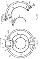
Selon la forme de réalisation représentée figures 9A et 9B les coquilles 8, 9 formant le capotage intérieur et les coquilles 28 et 29 formant le capotage extérieur sont articulées séparemment et peuvent s'ouvrir de même. Les coquilles du capotage extérieur portent sur leur surface intérieure des ailes longitudinales 31, 32 dirigées vers l'intérieur, de hauteur suffisante pour venir coopérer avec un joint 33, 34 porté par un rebord 35,36 des coquilles du capotage intérieur, et assurer l'étanchéité du canal du flux secondaire. Ce type de capotage est appelé capotage de type C. Dans cette forme de réalisation, les capotages intérieurs et extérieurs étant indépendants les charges auxquelles est soumis le premier ne sont pas transmises au second.According to the embodiment shown in Figures 9A and 9B the
Cependant, il peut être avantageux de réaliser l'enveloppe du flux secondaire à partir d'éléments solidarisés les uns aux autres afin d'améliorer la tenue de cette enveloppe aux efforts de pression. Mais si le système d'inverseur de poussée est monté sur le capot externe, il faut éviter la transmission des charges entre les deux capotages. Enfin, il faut pouvoir séparer l'élément intérieur de l'élément extérieur. La forme de réalisaion représentée aux figures 10A et 10B répond à ces conditions; les coquilles 37 et 38 du capotage extérieur portent des parois latérales 39, 40, s'étendant longitudinalement d'une extrémité à l'autre et dirigées vers l'intérieur, solidarisées à leur extrémité longitudinale par des joints à glissière 41, 42 aux coquilles 8 t 9 du capotage intérieur. Ces joints sont semblables aux éléments de guidage décrits dans notre demande de brevet français publié sous le numéro 2 496 533 et illustrée à la figure 14. Ces joints permettent une rotation limitée de chaque capot intérieur par rapport à la paroi 39, 40 correspondante. Une certaine flexibilité dans le sens vertical étant également nécessaire, on prévoit une liaison flexible, par ressort à lame par exemple entre ces parois 39, 40 et le joint à glissière. La plaque flottante est remplacée dans cette solution par des vérins (43) à double effet reliés par chaque extrémité à une des coquilles intérieures. Ces vérins assurant le serrage du capotage intérieur sur les brides du carter moteur 1, servent également à l'ouverture des deux capotages qui pivotent autour des articulations 44 fixées sur le pylône 4. Les verrous de fermeture 45 situés sur les bords intérieurs du capotage intérieur assurent également le maintien, en position fermée, du capotage extérieur. Ce type de capotage est appelé capotage de type D.However, it may be advantageous to produce the envelope of the secondary flow from elements secured to one another in order to improve the resistance of this envelope to pressure forces. However, if the thrust reverser system is mounted on the external cover, the transmission of loads between the two cowlings must be avoided. Finally, it must be possible to separate the interior element from the exterior element. The embodiment shown in Figures 10A and 10B meets these conditions; the
Selon la forme de réalisation représentée figure 11, les vérins 43 sont fixés sur une plaque intermédiaire 46. Ils sont disposés à l'avant et à l'arrière de la plaque. Quoiqu'il soit souhaitable que ces vérins soient alignés deux par deux afin de leur permettre d'agir dans un même plan pour le bouclage avant respectivement arrière, les problèmes d'encombrement peuvent conduire à une disposition où ils sont juxtaposés comme sur la figure 11. La plaque est fixée par boulonnage ou tout autre moyen à l'avant sur le carter ou la bride du carter 6 et à l'arrière sur l'anneau support 14.According to the embodiment shown in Figure 11, the
Comme mentionné plus haut, le capotage structural interne peut être adapté au cas d'un inverseur de poussée "soufflante". La figure 12A montre en demi-coupe un turboréacteur avec inverseur de flux sur l'air secondaire, l'inverseur étant inactif. La figure 12B montre le même inverseur en position active.As mentioned above, the internal structural cowling can be adapted to the case of a "blower" thrust reverser. FIG. 12A shows in half-section a turbojet with flow reverser on the secondary air, the reverser being inactive. Figure 12B shows the same inverter in the active position.
L'inverseur de poussée, prévu dans le capotage de la soufflante comporte, comme connu, des grilles d'inversion 47 disposées dans l'épaisseur de la nacelle, recouvertes lorsqu'il n'est pas utilisé d'un tronçon mobile 48 de capotage. Lors de l'utilisation, le tronçon 48 est translaté vers l'arrière pour dégager les grilles. Cette manoeuvre entraîne la mise en place des moyens d'obturation 49 de la veine secondaire en arrière des grilles ce qui a pour effet de faire refluer vers l'avant, à travers les grilles, tout le débit d'air provenant de la soufflante. Le tronçon 48 est maintenu dans son mouvement de translation par un dispositif de guidage 50 qui peut être du type de celui décrit dans le brevet français n° 2 496 533 et illustré sur la figure 14. Ces dispositifs sont prévus en nombre suffisant pour permettre la translation et le maintien du tronçon mobile 48.The thrust reverser, provided in the cowling of the blower comprises, as known, reversing
Les figures 13A et 13B représentent un capotage du type D semblable à celui des figures 10A et 10B avec application de la solution de la plaque intermédiaire (figure 11), et montrent le dispositif d'inverseur.Figures 13A and 13B show a type D cowling similar to that of Figures 10A and 10B with application of the solution of the intermediate plate (Figure 11), and show the reversing device.
Les dispositifs de guidage 50 sont disposés entre les parois latérales 39A, 39B, 40A, 40B et les tronçons 48A, 48B des coquilles 37, 38. Ces dispositifs sont constitués (figure 14) d'un rail de guidage 51 présentant une rainure cylindrique, fixé sur l'élément d'ossature 52 prolongeant la paroi latérale 39 ou 41. Dans la rainure coulisse un corps tubulaire cylindrique 53 comportant selon une génératrice une aile 54 dont l'extrémité est fixée par tout moyen connu sur le bord latéral du tronçon de capotage. Une fourrure 55, en un matériau presentant des bonnes caracteristiques de glissement et de résistance à l'usure, est interposée entre le rail et le corps tubulaire cylindrique.The guiding
Selon la réalisation représentée figure 14, l'élément d'ossature 52 porte latéralement deux ailes 56, 57 formant une rainure un U dans laquelle vient se fixer, par deux ailes parallèles 58, 59 le rail de guidage 51.According to the embodiment shown in FIG. 14, the
Le tronçon mobile 48 est formé comme le capotage extérieur de deux coquilles 48A et 48B qui sont fixées aux parois transversales supérieures 39A, 39B et inférieures 40A et 40B par les dispositifs de guidage 50. Lorsque le tronçon mobile 48 recouvre les grilles, le capotage peut s'ouvrir sous l'action des vérins 43, fixés sur la plaque support 46, maintenus entre la bride avant et l'anneau arrière du carter moteur 1, agissant sur le capotage structural interne 8, 9. Les bords inférieurs des deux parties de capotage 8, 9 portent, comme précédemment décrit, les verrous 45 assurant leur liaison.The
Sans sortir du cadre de l'invention, on peut envisager d'autres modes de réalisation qui n'ont pas été représentés; par exemple suivant les applications, les moyens de coulissement longitudinaux pourraient être disposés à l'aval plutôt qu'à l'amont; inversement le dispositif à broches radiales pourrait être monté à l'amont.Without departing from the scope of the invention, it is possible to envisage other embodiments which have not been shown; for example depending on the applications, the longitudinal sliding means could be arranged downstream rather than upstream; conversely, the device with radial pins could be mounted upstream.
Claims (22)
Applications Claiming Priority (2)
| Application Number | Priority Date | Filing Date | Title |
|---|---|---|---|
| FR8403509 | 1984-03-07 | ||
| FR8403509A FR2560854B1 (en) | 1984-03-07 | 1984-03-07 | STRUCTURAL HOODS PARTICIPATING IN THE ASSEMBLY RIGIDITY OF A TURBO-JET |
Publications (2)
| Publication Number | Publication Date |
|---|---|
| EP0155887A1 EP0155887A1 (en) | 1985-09-25 |
| EP0155887B1 true EP0155887B1 (en) | 1987-04-29 |
Family
ID=9301784
Family Applications (1)
| Application Number | Title | Priority Date | Filing Date |
|---|---|---|---|
| EP85400427A Expired EP0155887B1 (en) | 1984-03-07 | 1985-03-06 | Structural cover-doors participating in the total rigidity of a turbojet engine |
Country Status (4)
| Country | Link |
|---|---|
| US (1) | US4683717A (en) |
| EP (1) | EP0155887B1 (en) |
| DE (1) | DE3560143D1 (en) |
| FR (1) | FR2560854B1 (en) |
Families Citing this family (63)
| Publication number | Priority date | Publication date | Assignee | Title |
|---|---|---|---|---|
| GB2188987B (en) * | 1986-04-09 | 1990-02-14 | Rolls Royce | A turbofan gas turbine engine and mountings therefor |
| US4825648A (en) * | 1987-03-02 | 1989-05-02 | General Electric Company | Turbofan engine having a split cowl |
| US4785625A (en) * | 1987-04-03 | 1988-11-22 | United Technologies Corporation | Ducted fan gas turbine power plant mounting |
| FR2622507B1 (en) * | 1987-10-28 | 1990-01-26 | Snecma | |
| FR2622930B1 (en) * | 1987-11-06 | 1990-03-23 | Aerospatiale | HOOD FOR DOUBLE-FLOW TURBOREACTOR |
| FR2661213B1 (en) * | 1990-04-19 | 1992-07-03 | Snecma | AVIATION ENGINE WITH VERY HIGH DILUTION RATES AND OF THE SAID TYPE FRONT CONTRAFAN. |
| US5156360A (en) * | 1991-04-08 | 1992-10-20 | The Boeing Company | Flexible fire seal for overlapping cowl side edges |
| US5369954A (en) * | 1991-04-22 | 1994-12-06 | General Electric Company | Turbofan engine bypass and exhaust system |
| US5183223A (en) * | 1991-06-27 | 1993-02-02 | Rohr, Inc. | Interlocking ring fan jet engine support system |
| US5174525A (en) * | 1991-09-26 | 1992-12-29 | General Electric Company | Structure for eliminating lift load bending in engine core of turbofan |
| US5205513A (en) * | 1991-09-26 | 1993-04-27 | General Electric Company | Method and system for the removal of large turbine engines |
| GB9723022D0 (en) | 1997-11-01 | 1998-01-07 | Rolls Royce Plc | Gas turbine apparatus |
| GB0124446D0 (en) * | 2001-10-11 | 2001-12-05 | Short Brothers Ltd | Aircraft propulsive power unit |
| US6517027B1 (en) | 2001-12-03 | 2003-02-11 | Pratt & Whitney Canada Corp. | Flexible/fixed support for engine cowl |
| GB2384827A (en) * | 2002-01-30 | 2003-08-06 | Rolls Royce Plc | A Fastening Between The C-Duct and Core of a Ducted Fan Gas Turbine Engine. |
| FR2856379B1 (en) * | 2003-06-18 | 2006-11-24 | Airbus France | AIRCRAFT ENGINE HAVING BLOWER HOUSINGS AND THRUST INVERTERS SEPARATED BY REDUCED GAME |
| FR2866070B1 (en) | 2004-02-05 | 2008-12-05 | Snecma Moteurs | TURBOREACTOR WITH HIGH DILUTION RATE |
| US7275362B2 (en) * | 2004-09-08 | 2007-10-02 | The Boeing Company | Thrust reversers including latching mechanisms and methods for manufacturing such thrust reversers |
| US7419121B2 (en) * | 2004-12-09 | 2008-09-02 | Honeywell International Inc. | Integrated mount duct for use with airborne auxiliary power units and other turbomachines |
| US7571527B2 (en) * | 2005-03-29 | 2009-08-11 | The Boeing Company | Mandrel for fabrication of a monolithic composite nacelle panel |
| US20110101158A1 (en) * | 2005-03-29 | 2011-05-05 | The Boeing Company | Thrust Reversers Including Monolithic Components |
| US7690190B2 (en) * | 2005-05-11 | 2010-04-06 | The Boeing Company | Aircraft systems including cascade thrust reversers |
| US7559507B2 (en) * | 2005-06-27 | 2009-07-14 | The Boeing Company | Thrust reversers including locking assemblies for inhibiting deflection |
| US7600371B2 (en) | 2005-10-18 | 2009-10-13 | The Boeing Company | Thrust reversers including support members for inhibiting deflection |
| FR2896481B1 (en) * | 2006-01-23 | 2009-12-04 | Aircelle Sa | FIXING SYSTEM FOR COMPONENT ELEMENT OF A TURBOJET CAPACITY |
| FR2903076B1 (en) * | 2006-06-30 | 2009-05-29 | Aircelle Sa | STRUCTURING LUGGAGE |
| FR2909974B1 (en) | 2006-12-13 | 2009-02-06 | Aircelle Sa | NACELLE FOR TURBOJET DOUBLE FLOW |
| FR2912378B1 (en) * | 2007-02-14 | 2009-03-20 | Aircelle Sa | REACTION ENGINE NACELLE FOR AN AIRCRAFT |
| FR2914700B1 (en) * | 2007-04-04 | 2009-05-22 | Aircelle Sa | THRUST INVERTER FOR REACTION ENGINE |
| FR2916737B1 (en) * | 2007-06-01 | 2010-05-28 | Airbus France | AIRCRAFT ENGINE ASSEMBLY WITH SLIDING CARGO. |
| US8051664B2 (en) * | 2007-07-23 | 2011-11-08 | Pratt & Whitney Canada Corp. | Pre-loaded internal fuel manifold support |
| FR2920145B1 (en) * | 2007-08-20 | 2009-09-18 | Aircelle Sa | SHOCK ABSORBER TURBO BOREHOUSE FOR HALF SHELL |
| FR2920177B1 (en) * | 2007-08-20 | 2009-09-18 | Aircelle Sa | CONNECTING DEVICE FOR CONNECTING FIRST AND SECOND MOVING ELEMENTS TO ONE ANOTHER |
| FR2948636B1 (en) | 2009-07-31 | 2012-01-13 | Airbus Operations Sas | AIRCRAFT ENGINE ASSEMBLY INCLUDING A STRUCTURAL ENVELOPE FOR THE INTERNAL RADIAL DELIMITATION OF THE SECONDARY FLOW |
| US8621874B2 (en) * | 2009-08-25 | 2014-01-07 | Honeywell International Inc. | Turbomachine core coupling assembly |
| FR2952615B1 (en) * | 2009-11-18 | 2011-12-09 | Aircelle Sa | ASSEMBLY FOR MAINTAINING THE INTERFACE OF A FIXED EXTERNAL STRUCTURE OF A NACELLE AND A TURBOJET CARTER |
| US9057286B2 (en) * | 2010-03-30 | 2015-06-16 | United Technologies Corporation | Non-circular aft nacelle cowling geometry |
| FR2960855A1 (en) * | 2010-06-03 | 2011-12-09 | Aircelle Sa | NACELLE FOR TURBOJETACTOR WITH DEVICE FOR RECOVERING CIRCUMFERENTIAL EFFORTS |
| FR2961173B1 (en) * | 2010-06-09 | 2012-06-22 | Airbus Operations Sas | NACELLE INCORPORATING AN AIR INLET AT A CAP |
| WO2012037988A1 (en) * | 2010-09-24 | 2012-03-29 | Short Brothers Plc | Nacelle with hinged cowl doors enabling access to the engine |
| FR2980173B1 (en) * | 2011-09-16 | 2013-10-25 | Aircelle Sa | REPLACEMENT OF NACELLE FOR TURBOJET ENGINE |
| FR2981686B1 (en) * | 2011-10-21 | 2016-05-20 | Snecma | TURBOMACHINE COMPRISING A CONTRAROTATIVE PROPELLER RECEIVER SUPPORTED BY A STRUCTURAL ENVELOPE FIXED TO THE INTERMEDIATE CASE |
| FR2987401B1 (en) * | 2012-02-28 | 2017-05-12 | Snecma | METHOD FOR MAINTAINING AN ADAPTATION PART ON A TUBULAR HOUSING OF A TURBOMOTEUR, ADAPTATION PART AND CORRESPONDING HOLDING SYSTEM |
| FR2989952B1 (en) | 2012-04-27 | 2014-04-18 | Aircelle Sa | TURBO BOREHOLE WITH DOWNSTREAM SECTION |
| US9212607B2 (en) | 2012-07-18 | 2015-12-15 | Spirit Aerosystems, Inc. | Intermediate structure for independently de-mountable propulsion components |
| WO2014164238A1 (en) * | 2013-03-13 | 2014-10-09 | United Technologies Corporation | Gas turbine engine hydraulically operated nacelle latch |
| US9404507B2 (en) * | 2013-04-15 | 2016-08-02 | Mra Systems, Inc. | Inner cowl structure for aircraft turbine engine |
| US9714627B2 (en) * | 2013-11-15 | 2017-07-25 | Rohr, Inc. | Mounting of aircraft propulsion system outer sleeve and inner structure to pylon with distinct hinges |
| US9366202B2 (en) * | 2013-11-27 | 2016-06-14 | Rohr, Inc. | System and method for captured inner fixed structure |
| GB201322380D0 (en) * | 2013-12-18 | 2014-02-05 | Rolls Royce Plc | Gas turbine cowl |
| US9822733B2 (en) * | 2014-04-25 | 2017-11-21 | Rohr, Inc. | Aerodynamic feature for aft edge portions of thrust reverser lower bifurcation wall |
| FR3024435B1 (en) * | 2014-07-31 | 2016-08-26 | Airbus Operations Sas | GUIDED FOLDING BLOWER HOOD, FOR AIRCRAFT ENGINE ASSEMBLY |
| US9784129B2 (en) * | 2014-08-01 | 2017-10-10 | Pratt & Whitney Canada Corp. | Rear mount assembly for gas turbine engine |
| DE102014221052A1 (en) | 2014-10-16 | 2016-04-21 | Premium Aerotec Gmbh | Aircraft gas turbine thrust reverser with guide rail |
| US10479519B2 (en) * | 2015-12-31 | 2019-11-19 | United Technologies Corporation | Nacelle short inlet for fan blade removal |
| US10150568B2 (en) * | 2016-01-27 | 2018-12-11 | Rohr, Inc. | Thrust reverser compression rod with spring biased engagement |
| FR3047973B1 (en) | 2016-02-23 | 2018-03-09 | Airbus Operations | AIRCRAFT ENGINE ASSEMBLY, COMPRISING A MOTOR ATTACHING DEVICE EQUIPPED WITH STRUCTURAL MOBILE HOOKS CONNECTED TO THE CENTRAL CABIN |
| FR3053957B1 (en) * | 2016-07-12 | 2018-08-31 | Safran Nacelles | TURBOREACTOR NACELLE REAR ASSEMBLY COMPRISING A FIRE PROTECTION SEALING DEVICE |
| FR3064980B1 (en) * | 2017-04-05 | 2022-05-13 | Airbus Operations Sas | PROPULSION SYSTEM OF AN AIRCRAFT COMPRISING A NACELLE WITH AN IMPROVED OPENING SYSTEM |
| FR3074853B1 (en) * | 2017-12-13 | 2020-01-03 | Safran Nacelles | PROPELLENT ASSEMBLY FOR AN AIRCRAFT HAVING A SIX HOUR ASSEMBLY BOX |
| GB201909171D0 (en) * | 2019-06-26 | 2019-08-07 | Rolls Royce Plc | Gas turbine engine cowl doors |
| US11511874B2 (en) * | 2019-09-30 | 2022-11-29 | Rohr, Inc. | Linkage(s) between inner and outer cowl doors |
| US11427341B2 (en) | 2019-09-30 | 2022-08-30 | Rohr, Inc. | Linkage supporting a door of an aircraft propulsion system |
Family Cites Families (14)
| Publication number | Priority date | Publication date | Assignee | Title |
|---|---|---|---|---|
| CA875843A (en) * | 1971-07-20 | G. Dibble Charles | Low drag exhaust nozzle and nacelle arrangement for turbofan engines | |
| US3493212A (en) * | 1968-06-24 | 1970-02-03 | Westinghouse Electric Corp | Rotary machine apparatus |
| US3541794A (en) * | 1969-04-23 | 1970-11-24 | Gen Electric | Bifurcated fan duct thrust reverser |
| GB1318748A (en) * | 1970-08-11 | 1973-05-31 | Secr Defence | Gas turgine ducted fan engines for aircraft |
| US3844115A (en) * | 1973-02-14 | 1974-10-29 | Gen Electric | Load distributing thrust mount |
| US4055041A (en) * | 1974-11-08 | 1977-10-25 | The United States Of America As Represented By The Administrator Of The National Aeronautics And Space Administration | Integrated gas turbine engine-nacelle |
| FR2291091A1 (en) * | 1974-11-13 | 1976-06-11 | Snecma | MOUNTING DEVICE ON AIRCRAFT OF A TURBOREACTOR |
| GB1516980A (en) * | 1974-12-24 | 1978-07-05 | Rolls Royce | Mounting ducted fan gas turbine engines on aircraft |
| FR2337258A1 (en) * | 1976-01-03 | 1977-07-29 | Plessey Handel Investment Ag | Jet engine thrust reverser - has shutters connected to operating cylinders by scissors linkages |
| GB2061389B (en) * | 1979-10-23 | 1983-05-18 | Rolls Royce | Rod installation for a gas turbine engine |
| US4361296A (en) * | 1980-03-10 | 1982-11-30 | The Boeing Company | Uniflange coupling assembly |
| GB2114661B (en) * | 1980-10-21 | 1984-08-01 | Rolls Royce | Casing structure for a gas turbine engine |
| FR2496766A1 (en) * | 1980-12-23 | 1982-06-25 | Snecma | MOBILE FAIRING GUIDING DEVICE OF A PUSH REVERSING SYSTEM |
| US4471609A (en) * | 1982-08-23 | 1984-09-18 | The Boeing Company | Apparatus and method for minimizing engine backbone bending |
-
1984
- 1984-03-07 FR FR8403509A patent/FR2560854B1/en not_active Expired
-
1985
- 1985-02-20 US US06/703,439 patent/US4683717A/en not_active Expired - Fee Related
- 1985-03-06 EP EP85400427A patent/EP0155887B1/en not_active Expired
- 1985-03-06 DE DE8585400427T patent/DE3560143D1/en not_active Expired
Also Published As
| Publication number | Publication date |
|---|---|
| DE3560143D1 (en) | 1987-06-04 |
| FR2560854B1 (en) | 1986-09-12 |
| EP0155887A1 (en) | 1985-09-25 |
| FR2560854A1 (en) | 1985-09-13 |
| US4683717A (en) | 1987-08-04 |
Similar Documents
| Publication | Publication Date | Title |
|---|---|---|
| EP0155887B1 (en) | Structural cover-doors participating in the total rigidity of a turbojet engine | |
| CA2281619C (en) | Aircraft propulsion unit with fan cowls equipped with maintaining and positioning safety elements | |
| EP1902951B1 (en) | Aircraft propulsion system with integrated pylon | |
| EP1905689B1 (en) | Integrated propulsion system comprising a turbofan engine | |
| WO1992005356A1 (en) | Turbojet thrust reverser with doors associated with an upstream panel | |
| EP1976758B1 (en) | Fixing system for a component of a turbine nacelle | |
| FR2683859A1 (en) | DOUBLE FLOW TURBOREACTOR DRIVE INVERTER. | |
| WO2008043903A2 (en) | Bypass turbojet engine nacelle | |
| EP0853192A1 (en) | Thrust reverser with optimized cascade actuator position | |
| FR2965589A1 (en) | PUSH INVERTER | |
| FR2920137A1 (en) | FIXING A STRUCTURE OF A TURBOJET NACELLE BY A REINFORCED KNIFE / GRIP BRIDGE | |
| EP2509870B1 (en) | Engine nacelle aft door assembly | |
| FR2966882A1 (en) | THRUST INVERTER FOR AIRCRAFT TURBOJET ENGINE WITH REDUCED ACTUATOR NUMBERS | |
| EP0413635B1 (en) | Thrust reverser for a jet engine | |
| EP2588370B1 (en) | Turbojet engine nacelle | |
| EP3867503A1 (en) | Engine assembly for an aircraft having an air-oil exchanger system support with optimized attachment | |
| CA2811481A1 (en) | Aircraft propulsion assembly | |
| EP1046806B1 (en) | Vectoriable gimbal nozzle | |
| FR2913664A1 (en) | Nacelle for turbojet engine of aeroplane, has rear section with external structure that is connected to downstream part of casing of fan to support engine, and attachment unit attaching nacelle to strut destined to be connected to fan | |
| EP2841340B1 (en) | Turbofan engine nacelle with downstream section | |
| EP0362051B1 (en) | Bidimensional ejection nozzle for a turbine and its control system | |
| WO2022167754A1 (en) | Thrust reverser comprising movable grids and cowls assembled by recessing | |
| EP2893179A1 (en) | Front frame for a cascade thrust reverser structure | |
| EP0748932A1 (en) | Nozzle with a variable geometry throat | |
| FR2526872A1 (en) | THRUST INVERTER WITH DOOR IN PARTICULAR FOR A REACTION AIRCRAFT ENGINE |
Legal Events
| Date | Code | Title | Description |
|---|---|---|---|
| PUAI | Public reference made under article 153(3) epc to a published international application that has entered the european phase |
Free format text: ORIGINAL CODE: 0009012 |
|
| 17P | Request for examination filed |
Effective date: 19850316 |
|
| AK | Designated contracting states |
Designated state(s): DE FR GB |
|
| 17Q | First examination report despatched |
Effective date: 19860828 |
|
| GRAA | (expected) grant |
Free format text: ORIGINAL CODE: 0009210 |
|
| AK | Designated contracting states |
Kind code of ref document: B1 Designated state(s): DE FR GB |
|
| REF | Corresponds to: |
Ref document number: 3560143 Country of ref document: DE Date of ref document: 19870604 |
|
| PLBE | No opposition filed within time limit |
Free format text: ORIGINAL CODE: 0009261 |
|
| STAA | Information on the status of an ep patent application or granted ep patent |
Free format text: STATUS: NO OPPOSITION FILED WITHIN TIME LIMIT |
|
| 26N | No opposition filed | ||
| PGFP | Annual fee paid to national office [announced via postgrant information from national office to epo] |
Ref country code: FR Payment date: 19950120 Year of fee payment: 11 |
|
| PGFP | Annual fee paid to national office [announced via postgrant information from national office to epo] |
Ref country code: GB Payment date: 19950227 Year of fee payment: 11 |
|
| PGFP | Annual fee paid to national office [announced via postgrant information from national office to epo] |
Ref country code: DE Payment date: 19950530 Year of fee payment: 11 |
|
| PG25 | Lapsed in a contracting state [announced via postgrant information from national office to epo] |
Ref country code: GB Effective date: 19960306 |
|
| GBPC | Gb: european patent ceased through non-payment of renewal fee |
Effective date: 19960306 |
|
| PG25 | Lapsed in a contracting state [announced via postgrant information from national office to epo] |
Ref country code: FR Effective date: 19961129 |
|
| PG25 | Lapsed in a contracting state [announced via postgrant information from national office to epo] |
Ref country code: DE Effective date: 19961203 |
|
| REG | Reference to a national code |
Ref country code: FR Ref legal event code: ST |