EP0155724B1 - Method and apparatus for checking lubrication volume in a disc cutterbar - Google Patents
Method and apparatus for checking lubrication volume in a disc cutterbar Download PDFInfo
- Publication number
- EP0155724B1 EP0155724B1 EP85200261A EP85200261A EP0155724B1 EP 0155724 B1 EP0155724 B1 EP 0155724B1 EP 85200261 A EP85200261 A EP 85200261A EP 85200261 A EP85200261 A EP 85200261A EP 0155724 B1 EP0155724 B1 EP 0155724B1
- Authority
- EP
- European Patent Office
- Prior art keywords
- header
- support bar
- rotary cutting
- lubricant
- tilt
- Prior art date
- Legal status (The legal status is an assumption and is not a legal conclusion. Google has not performed a legal analysis and makes no representation as to the accuracy of the status listed.)
- Expired
Links
- 238000000034 method Methods 0.000 title claims description 16
- 238000005461 lubrication Methods 0.000 title description 2
- 239000000314 lubricant Substances 0.000 claims description 51
- 238000003306 harvesting Methods 0.000 claims description 30
- 230000001154 acute effect Effects 0.000 claims description 13
- 230000005540 biological transmission Effects 0.000 claims description 13
- 239000000463 material Substances 0.000 claims description 12
- 239000012530 fluid Substances 0.000 claims description 7
- 230000000694 effects Effects 0.000 claims description 6
- 230000000284 resting effect Effects 0.000 claims description 4
- 230000001419 dependent effect Effects 0.000 claims description 2
- 230000003750 conditioning effect Effects 0.000 description 10
- 238000010276 construction Methods 0.000 description 1
- 239000004459 forage Substances 0.000 description 1
- 238000013021 overheating Methods 0.000 description 1
- 238000007665 sagging Methods 0.000 description 1
Images


Classifications
-
- A—HUMAN NECESSITIES
- A01—AGRICULTURE; FORESTRY; ANIMAL HUSBANDRY; HUNTING; TRAPPING; FISHING
- A01D—HARVESTING; MOWING
- A01D69/00—Driving mechanisms or parts thereof for harvesters or mowers
- A01D69/12—Lubrication
-
- F—MECHANICAL ENGINEERING; LIGHTING; HEATING; WEAPONS; BLASTING
- F16—ENGINEERING ELEMENTS AND UNITS; GENERAL MEASURES FOR PRODUCING AND MAINTAINING EFFECTIVE FUNCTIONING OF MACHINES OR INSTALLATIONS; THERMAL INSULATION IN GENERAL
- F16N—LUBRICATING
- F16N19/00—Lubricant containers for use in lubricators or lubrication systems
Definitions
- the present invention relates generally to hay harvesting machines of the type comprising a disc cutterbar and such as shown in DE-A-1.582.344 and FR-A-2.326.857.
- a disc cutterbar such as shown in DE-A-1.582.344 and FR-A-2.326.857.
- One such type of harvesting machine is formed by a so-called disc mower-conditioner.
- the invention is concerned with an improved system for determining the proper amount of lubricant to be placed within the rotary cutterbar of such a harvesting machine.
- a mower-conditioner severs standing crop material and conveys the severed crop material rearwardly into a conditioning mechanism.
- a disc mower-conditioner is provided with a disc cutterbar having a number of transversely spaced rotatable cutter members operable to sever standing crop material by an impact action.
- a conditioning mechanism mounted rearwardly of the disc cutterbar is operable to receive severed crop material from the disc cutterbar for conditioning.
- a disc cutterbar includes a generally hollow support bar in which is housed a drive transmission mechanism, generally in the form of a series of intermeshing gears.
- the disc cutters are rotatably supported on the support bar and connected to a corresponding gear to effect rotation thereof when the drive transmission mechanism is rotatably driven by a primary drive mechanism.
- a correct amount of lubricant must be present within the support bar.
- the support bar is considerably wider and longer than it is thick, making the correct depth of lubricant a very critical value since too much lubricant will cause overheating and too little lubricant will not provide adequate lubrication for the drive transmission gears.
- a harvesting machine which comprises rotary cutting means and lift means operably associated with the rotary cutting means for selectively moving said rotary cutting means between an operative position and a transport position.
- the rotary cutting means of said harvesting machine comprise:
- the invention is characterized in that tilt means operably associated with the support bar, are selectively positionable in an inoperative position and a tilt position; the arrangement being such that, when the harvesting machine is positioned over a substantially level area of ground, the lift means are in the condition normally corresponding to the operative position of the rotary cutting means and the tilt means are held in the tilt position, the second transverse end of the support bar is positioned higher than the first transverse end thereof whereby said support bar is positioned at a predetermined acute angle inclined to the horizontal such that the supply of lubricant therein is caused to flow to the lower transverse end and said fill hole is positioned such that the fluid level of the lubricant is at the fill hole when the support bar is positioned at said predetermined acute angle and when the proper volume of lubricant is present within the support bar.
- the harvesting machine further also may comprise:
- the tilt means preferably are operable to tilt the header with the rotary cutting means thereon at the predetermined acute angle inclined to the horizontal.
- the rotary cutting means may be provided with ground engaging means proximate to each transverse end of the support bar and the tilt means may be operably associated with the second side wall of the header and be positionable in two positions. In a first, retracted position of the tilt means, the ground engaging means at both transverse ends of the support bar are free to engage the ground and in a second, tilt position, the tilt means engage the ground preventing the ground engaging means proximate to said tilt means from engaging the ground.
- the tilt means are in the form of a jackstand adjustably mounted on the header proximate to the second transverse end of the support bar and selectively positionable in a retracted position and a tilt position to elevate the second header side wall. It is a feature of this invention that the jackstand can be operated in conjunction with the header lift mechanism to facilitate the checking of the lubricant volume within the disc cutterbar.
- the method is characterized in the steps of:
- a top plan view of a hay harvesting machine commonly referred to as a disc mower-conditioner
- Any left and right references are used as a matter of convenience and are determined by standing at the rear of the mower-conditioner and facing in the direction of travel.
- the mower-conditioner 10 is shown in the form of a pull-type machine having a draft member 12 pivotally connected to the frame 14 of the machine 10.
- the frame 14 includes a main transverse support beam 15 to which are connected downwardly depending legs 17 mounting wheels 18 for mobilely supporting the machine 10 over the ground G, as best seen in Fig. 2.
- the mower-conditioner 10 includes a crop harvesting header 20 floatingly supported for movement over the ground G relative to the frame 14 by the counterbalancing mechanism 22 and upper and lower links 23, 24 interconnecting the header 20 and the frame 14.
- the header 20 is provided with a crop cutting mechanism 25, seen in the form of a disc cutterbar 26, such as a Kuhn three meter, six rotor rotary cutterbar, having a plurality of transversely spaced disc cutter members 28 operable to sever standing crop material by an impact action.
- a conditioning mechanism 30 is mounted on the header 20 rearwardly of the cutting mechanism 25 to receive and condition crop material severed by the cutterbar 26.
- the header 20 can be raised relative to the frame 14 in a conventional manner by a header lift mechanism 29, shown in the form of a hydraulic cylinder interconnecting each lower link 24 and the corresponding leg 17.
- the conditioning mechanism 30 includes a pair of cooperable, generally vertically spaced transverse conditioning rolls 32, 34 operable to condition severed crop material passing therebetween.
- Each roll 32, 34 is rotatably mounted within the header 20 such that the axis of rotation 33 of the upper conditioning roll 32 is spaced slightly forwardly of the axis of rotation 35 of the lower conditioning roll 34, so that the nip 37 formed therebetween is facing slightly downwardly toward the disc cutterbar 26.
- the preferred embodiment of the conditioning roll construction shown in Figs. 1 and 2 is of the intermeshing lug design.
- a drive mechanism 39 provides a source of rotational power to both the cutting mechanism 25 and the conditioning mechanism 30 in a conventional manner.
- the disc cutterbar 26 includes a transverse support bar 40 having vertically spaced upper and lower surfaces 42, 44, respectively, and defining a generally hollow beam for the housing of drive transmission gears 45 within the support bar 40.
- the cutter members 28 are rotatably mounted on the upper surface 42 of the support bar 40 and are connected to a corresponding drive transmission gear 45 to effect rotation thereof.
- the upper surface 42 is also provided with a pair of fill holes 46,48 spaced inwardly of the corresponding ends of the support bar 40. Each fill hole 46, 48 is provided with a removable plug 49 to permit access to the interior of the support bar 40.
- Ground engaging shoes 41 are affixed to the lower surface 44 of the support bar 40 to elevate the support bar 40 above the ground G.
- a header tilt mechanism 50 is affixed to the left side sheet 21 of the header 20 to effect a tilting of the header 20 at a predetermined angle A relative to horizontal.
- the header tilt mechanism includes a bracket 52 affixed to the side sheet 21 for slidably receiving a jackstand 55 having a pair of openings 56, 57 extending therethrough.
- the position of the jackstand 55 relative to the bracket 52 can be secured through the use of a fastening member 59 extending through a corresponding hole in the bracket 52 and either the tilt opening 56 or the retracted opening 57, as will be described in further detail below.
- the jackstand 55 can be utilized to tiltthe cutterbar 26 at the angle A to drain the fluid lubricant L within the support bar 40 to the lower end of the support bar 40. If the right fill hole 48 is positioned in the upper surface 42 such that the free volume of the interior of the support bar 40 lying vertically beneath this right fill hole 48 when the support bar is inclined at the angle A, is equal to the total recommended volume of fluid lubricant L for proper operation of the drive transmission gears within the support bar 40, the correct volume of lubricant L can quickly and easily be attained by filling the support bar 40 with lubricant L through the right fill hole 48 until the level of the lubricant L is at the fill hole 48.
- the header 20 can be moved from the operative position seen in Fig. 4 to a raised position seen in Fig. 5 by manipulation of the header lift mechanism 29.
- the jackstand By removing the fastening member 59 from the retracted opening 57 of the jackstand 55, the jackstand can be moved from the retracted position seen in phantom in Fig. 5 to the tilting position shown in solid lines in Fig. 5.
- a reengagement of the fastening member 59 through the tilt opening 56 will lock the position of the jackstand 55 relative to the bracket 52 and permit the operator to affect a tilting of the cutterbar 26.
- the header 20 By lowering the header 20 by appropriate manipulation of the header lift mechanism, the header 20 will assume the tilted position seen in Fig. 6 with the right ground engaging shoe 41 resting on the ground G and the left end of the header 20 being supported on the jackstand 55, such that the cutterbar 26 is tilted at the angle A relative to horizontal, when the machine 10 is situated on substantially level ground G.
- the level of the lubricant L is at the rightfill hole 48.
- the left fill hole 46 is utilized when adding lubricant through the right fill hole 48 to facilitate the removal of air from within the support bar 40.
Landscapes
- Engineering & Computer Science (AREA)
- General Engineering & Computer Science (AREA)
- Life Sciences & Earth Sciences (AREA)
- Environmental Sciences (AREA)
- Mechanical Engineering (AREA)
- Harvester Elements (AREA)
Description
- The present invention relates generally to hay harvesting machines of the type comprising a disc cutterbar and such as shown in DE-A-1.582.344 and FR-A-2.326.857. One such type of harvesting machine is formed by a so-called disc mower-conditioner. More particularly, the invention is concerned with an improved system for determining the proper amount of lubricant to be placed within the rotary cutterbar of such a harvesting machine.
- Mower-conditioners have been provided for the harvesting of hay for a number of years. A mower-conditioner severs standing crop material and conveys the severed crop material rearwardly into a conditioning mechanism. A disc mower-conditioner is provided with a disc cutterbar having a number of transversely spaced rotatable cutter members operable to sever standing crop material by an impact action. A conditioning mechanism mounted rearwardly of the disc cutterbar is operable to receive severed crop material from the disc cutterbar for conditioning.
- A disc cutterbar includes a generally hollow support bar in which is housed a drive transmission mechanism, generally in the form of a series of intermeshing gears. The disc cutters are rotatably supported on the support bar and connected to a corresponding gear to effect rotation thereof when the drive transmission mechanism is rotatably driven by a primary drive mechanism. For the proper operation of the drive transmission gears, a correct amount of lubricant must be present within the support bar. Typically, the support bar is considerably wider and longer than it is thick, making the correct depth of lubricant a very critical value since too much lubricant will cause overheating and too little lubricant will not provide adequate lubrication for the drive transmission gears. Further complicating the determination of the proper volume of lubricant within the cutterbar is the difficulty in determining when the cutterbar is properly leveled in both the side- to-side direction and the front to rear direction. Furthermore, because of the weight of the cutterbar and its length, the support bars are prone to sagging near the center resulting in the lubricant being non-uniformly distributed within the support bar even when the cutterbar is properly leveled. Accordingly, not only is leveling the support bar in two directions inconvenient, determination of the volume of lubricant in the support bar can also be unreliable as it is dependent upon the condition of the cutterbar being serviced.
- In the art of disc mowers it is known to position the cutterbar in a vertical position on one of its fore-and-aft edges for accurately and reliably checking the lubricant level in the disc cutterbar. This method and the apparatus therefore are disclosed a.o. in the Operator's Manual for the Sperry New Holland Disc Mower model 438, page 7 (edition 552915-6000-7646). This method is unpractical for a disc cutterbar integrated in e.g. a mower-conditioner.
- It is an object of this invention to provide a harvesting machine of the type comprising a disc cutterbar and which is arranged to facilitate an accurate and reliable checking of the lubricant level in the disc cutterbar.
- It is also an object of this invention to provide a more reliable and accurate method for determining the proper volume of lubricant in the disc cutterbar of such a harvesting machine.
- According to the instant invention, a harvesting machine is provided which comprises rotary cutting means and lift means operably associated with the rotary cutting means for selectively moving said rotary cutting means between an operative position and a transport position. The rotary cutting means of said harvesting machine comprise:
- a generally hollow support bar having a fill hole positioned at a predetermined distance from a first transverse end thereof for introduction of lubricant therein,
- drive transmission members housed within the support bar, and
- a plurality of transversely spaced disc cutter members rotatably mounted on the support bar and operably connected to the drive transmission members therein to effect a rotation of said cutter members to sever standing crop material by impact action.
- The invention is characterized in that tilt means operably associated with the support bar, are selectively positionable in an inoperative position and a tilt position; the arrangement being such that, when the harvesting machine is positioned over a substantially level area of ground, the lift means are in the condition normally corresponding to the operative position of the rotary cutting means and the tilt means are held in the tilt position, the second transverse end of the support bar is positioned higher than the first transverse end thereof whereby said support bar is positioned at a predetermined acute angle inclined to the horizontal such that the supply of lubricant therein is caused to flow to the lower transverse end and said fill hole is positioned such that the fluid level of the lubricant is at the fill hole when the support bar is positioned at said predetermined acute angle and when the proper volume of lubricant is present within the support bar.
- The harvesting machine further also may comprise:
- a mobile frame,
- crop processing means for processing crop material fed thereto (e.g. when the harvesting machine is a disc mower-conditioner, the crop processing means are formed by conditioner means), and
- a header floatingly supported from the frame for generally vertical movement relative thereto; the header having first and second transversely spaced apart sidewalls, the rotary cutting means being mounted on the header forwardly of the crop processing means, and the lift means operably interconnecting the frame and the header for
- The tilt means preferably are operable to tilt the header with the rotary cutting means thereon at the predetermined acute angle inclined to the horizontal. The rotary cutting means may be provided with ground engaging means proximate to each transverse end of the support bar and the tilt means may be operably associated with the second side wall of the header and be positionable in two positions. In a first, retracted position of the tilt means, the ground engaging means at both transverse ends of the support bar are free to engage the ground and in a second, tilt position, the tilt means engage the ground preventing the ground engaging means proximate to said tilt means from engaging the ground.
- Preferably, the tilt means are in the form of a jackstand adjustably mounted on the header proximate to the second transverse end of the support bar and selectively positionable in a retracted position and a tilt position to elevate the second header side wall. It is a feature of this invention that the jackstand can be operated in conjunction with the header lift mechanism to facilitate the checking of the lubricant volume within the disc cutterbar.
- According to another aspect of the invention, a method is provided for filling the proper volume of lubricant in a harvesting machine having a rotary cutting mechanism including a hollow support bar housing drive transmission means and a desired volume of fluid lubricant therewithin; the support bar having a fill hole for the introduction of lubricant therein. The method is characterized in the steps of:
- raising the rotary cutting mechanism from an operative position to an elevated position;
- moving a tilting mechanism disposed generally at or adjacent one transverse end of the rotary cutting mechanism from an inoperative position to an operative tilt position for therewith restricting subsequent lowering movement of said one transverse end of the rotary cutting mechanism;
- lowering the rotary cutting mechanism until it is supported at said one transverse end thereof by the tilting mechanism on the one hand and until the opposite transverse end thereof has returned substantially to the level of said operative position of the rotary cutting mechanism on the other hand whereby said rotary cutting mechanism assumes a tilted position at a predetermined acute angle relative to the horizontal; the position of the fill hole being such that the free volume of the support bar below the fill hole when the rotary cutting mechanism is at said predetermined acute angle, is substantially equal to the desired volume of lubricant,
- adjusting the amount of lubricant within the support bar until the level thereof is at the fill hole, and
- then returning the rotary cutting mechanism from the tilted position to the operative position.
- It is an advantage of the invention that, on the one hand, irregularities in the structure of the cutterbar will have minimal effects on the checking of the lubricant volume within the cutterbar and, on the other hand, the proper lubricant volume for the disc cutterbar can be obtained quickly and easily.
- It is also a feature of this invention that the cutterbar is positioned at the necessary acute angle when one end of the cutterbar is supported on the ground and the other end of the cutterbar is supported by the jackstand resting upon the ground at substantially the same level as the lower end of the cutterbar.
- The advantages of this invention will become apparent upon consideration of the following detailed disclosure of the invention, especially when taken in conjunction with the accompanying drawings wherein:
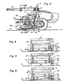
- Fig. 1 is a top plan view of a disc mower-conditioner incorporating the principles of the instant invention and with a portion of the draft member being broken away;
- Fig. 2 is a side elevational view of a disc mower-conditioner seen in Fig. 1 with portions being broken away to better show the invention;
- Fig. 3 is an enlarged cross-sectional view taken along the lines 3-3 of Fig. 2, but with the machine elements being shown in the lubricant checking mode and with selective structures being broken away to better show the invention; the thickness of the disc cutterbar support bar being somewhat exaggerated to better depict the invention and the fill plugs being shown exploded 10 upwardly from their respective holes; and
- Figs. 4, 5 and 6 are schematic front elevational views of the disc mower-conditioner seen in Fig. 1 for sequentially depicting the steps for checking the lubricant volume in the disc cutterbar, the fill plugs in Fig. 6 being shown exploded upwardly from their respective holes.
- Referring now to the drawings, and particularly to Fig. 1, a top plan view of a hay harvesting machine, commonly referred to as a disc mower-conditioner, can be seen. Any left and right references are used as a matter of convenience and are determined by standing at the rear of the mower-conditioner and facing in the direction of travel. The mower-
conditioner 10 is shown in the form of a pull-type machine having adraft member 12 pivotally connected to theframe 14 of themachine 10. Theframe 14 includes a maintransverse support beam 15 to which are connected downwardly dependinglegs 17mounting wheels 18 for mobilely supporting themachine 10 over the ground G, as best seen in Fig. 2. - Referring to Figs. 1 and 2, the mower-
conditioner 10 includes acrop harvesting header 20 floatingly supported for movement over the ground G relative to theframe 14 by thecounterbalancing mechanism 22 and upper andlower links header 20 and theframe 14. Theheader 20 is provided with acrop cutting mechanism 25, seen in the form of adisc cutterbar 26, such as a Kuhn three meter, six rotor rotary cutterbar, having a plurality of transversely spaceddisc cutter members 28 operable to sever standing crop material by an impact action. Aconditioning mechanism 30 is mounted on theheader 20 rearwardly of thecutting mechanism 25 to receive and condition crop material severed by thecutterbar 26. Theheader 20 can be raised relative to theframe 14 in a conventional manner by aheader lift mechanism 29, shown in the form of a hydraulic cylinder interconnecting eachlower link 24 and thecorresponding leg 17. - The
conditioning mechanism 30 includes a pair of cooperable, generally vertically spacedtransverse conditioning rolls roll header 20 such that the axis of rotation 33 of theupper conditioning roll 32 is spaced slightly forwardly of the axis ofrotation 35 of thelower conditioning roll 34, so that thenip 37 formed therebetween is facing slightly downwardly toward thedisc cutterbar 26. The preferred embodiment of the conditioning roll construction shown in Figs. 1 and 2 is of the intermeshing lug design. Adrive mechanism 39 provides a source of rotational power to both thecutting mechanism 25 and theconditioning mechanism 30 in a conventional manner. - Referring now to Figs. 1, 2 and 3, the apparatus for determining the proper lubricant volume within the
disc cutterbar 26 can be seen. Thedisc cutterbar 26 includes atransverse support bar 40 having vertically spaced upper andlower surfaces drive transmission gears 45 within thesupport bar 40. Thecutter members 28 are rotatably mounted on theupper surface 42 of thesupport bar 40 and are connected to a correspondingdrive transmission gear 45 to effect rotation thereof. Theupper surface 42 is also provided with a pair offill holes support bar 40. Eachfill hole removable plug 49 to permit access to the interior of thesupport bar 40.Ground engaging shoes 41 are affixed to thelower surface 44 of thesupport bar 40 to elevate thesupport bar 40 above the ground G. - A
header tilt mechanism 50 is affixed to theleft side sheet 21 of theheader 20 to effect a tilting of theheader 20 at a predetermined angle A relative to horizontal. The header tilt mechanism includes abracket 52 affixed to theside sheet 21 for slidably receiving ajackstand 55 having a pair ofopenings jackstand 55 relative to thebracket 52 can be secured through the use of afastening member 59 extending through a corresponding hole in thebracket 52 and either the tilt opening 56 or the retractedopening 57, as will be described in further detail below. - Referring now to Figs. 3-6, it can be seen that the
jackstand 55 can be utilized to tiltthe cutterbar 26 at the angle A to drain the fluid lubricant L within thesupport bar 40 to the lower end of thesupport bar 40. If theright fill hole 48 is positioned in theupper surface 42 such that the free volume of the interior of thesupport bar 40 lying vertically beneath thisright fill hole 48 when the support bar is inclined at the angle A, is equal to the total recommended volume of fluid lubricant L for proper operation of the drive transmission gears within thesupport bar 40, the correct volume of lubricant L can quickly and easily be attained by filling thesupport bar 40 with lubricant L through theright fill hole 48 until the level of the lubricant L is at thefill hole 48. - In operation, the
header 20 can be moved from the operative position seen in Fig. 4 to a raised position seen in Fig. 5 by manipulation of theheader lift mechanism 29. By removing thefastening member 59 from the retractedopening 57 of thejackstand 55, the jackstand can be moved from the retracted position seen in phantom in Fig. 5 to the tilting position shown in solid lines in Fig. 5. A reengagement of thefastening member 59 through thetilt opening 56 will lock the position of thejackstand 55 relative to thebracket 52 and permit the operator to affect a tilting of thecutterbar 26. By lowering theheader 20 by appropriate manipulation of the header lift mechanism, theheader 20 will assume the tilted position seen in Fig. 6 with the rightground engaging shoe 41 resting on the ground G and the left end of theheader 20 being supported on thejackstand 55, such that thecutterbar 26 is tilted at the angle A relative to horizontal, when themachine 10 is situated on substantially level ground G. - As is noted above, when the
support bar 40 has the proper amount of fluid lubricant L, the level of the lubricant L is at therightfill hole 48. Theleft fill hole 46 is utilized when adding lubricant through theright fill hole 48 to facilitate the removal of air from within thesupport bar 40. Once it has been determined that the proper volume of lubricant L is present within thesupport bar 40, the procedure noted above is reversed. With theheader 20 raised by theheader lift mechanism 29, thejackstand 55 can be returned to its retracted position by a repositioning of thefastening member 59 through the retractedopening 57 in thejackstand 55 and the corresponding opening in thebracket 52. A subsequent manipulation of theheader lift mechanism 29 can return the header to the operative position seen in Fig. 4. Although the preferred embodiment for the instant invention is shown with respect to a disc mower-conditioner, one skilled in the art will readily realize that the disclosed method and apparatus for checking the volume of lubricant within a disc cutterbar can be equally applicable to a conventional rotary mower. It also will be understood that the invention is equally well applicable on still other sorts of harvesting machines of the type comprising a disc type cutterbar, such as e.g. a forage harvester having a disc type direct cut attachment. In such a harvesting machine the conditioner means, of course, are replaced by a cutterhead and associated shear- bar. - One skilled in the art also will readily realize that an alternative embodiment of the above described invention would be to provide a linkage selectively attachable between the elevatable end of the header and the
frame 14 of the machine such that as theheader 20 is lowered, one end would be positioned higher than the other end with thesupport bar 40 being inclined at angle A to permit the lubricant to flow down to the lower end without one end of theheader 20 resting on the ground G.
Claims (16)
characterized in that:
characterized in that:
characterized in that:
Applications Claiming Priority (2)
| Application Number | Priority Date | Filing Date | Title |
|---|---|---|---|
| US585726 | 1984-03-02 | ||
| US06/585,726 US4539797A (en) | 1984-03-02 | 1984-03-02 | Method and apparatus for checking lubricant volume in a disc cutterbar |
Publications (2)
| Publication Number | Publication Date |
|---|---|
| EP0155724A1 EP0155724A1 (en) | 1985-09-25 |
| EP0155724B1 true EP0155724B1 (en) | 1989-12-06 |
Family
ID=24342697
Family Applications (1)
| Application Number | Title | Priority Date | Filing Date |
|---|---|---|---|
| EP85200261A Expired EP0155724B1 (en) | 1984-03-02 | 1985-02-26 | Method and apparatus for checking lubrication volume in a disc cutterbar |
Country Status (5)
| Country | Link |
|---|---|
| US (1) | US4539797A (en) |
| EP (1) | EP0155724B1 (en) |
| AU (1) | AU565587B2 (en) |
| CA (1) | CA1236984A (en) |
| DE (1) | DE3574558D1 (en) |
Families Citing this family (5)
| Publication number | Priority date | Publication date | Assignee | Title |
|---|---|---|---|---|
| US5012634A (en) * | 1990-06-01 | 1991-05-07 | Deere & Company | Cutterbar gear housing design for containing gear lubrication fluid |
| US8006470B2 (en) * | 2005-10-11 | 2011-08-30 | Agco Corporation | Crop harvester having metal conditioner rolls with herringbone rib pattern |
| US20090094955A1 (en) * | 2007-10-11 | 2009-04-16 | Rosenbalm Allan W | Crop Conditioning Roll With Herringbone Flutes Having A Radius |
| US8056310B2 (en) * | 2009-12-11 | 2011-11-15 | Cnh America Llc | Conditioner rolls having tread pattern coordinated with cutterbar crop discharge pattern |
| US20110154793A1 (en) * | 2009-12-30 | 2011-06-30 | Curtis Ernst | Forage chopper header for harvesting both standing and down crop material |
Family Cites Families (9)
| Publication number | Priority date | Publication date | Assignee | Title |
|---|---|---|---|---|
| US3141341A (en) * | 1961-11-16 | 1964-07-21 | Allen R Hutchinson | Cultivator drive assembly |
| US3416295A (en) * | 1965-10-24 | 1968-12-17 | Jacobsen Mfg Co | Rotary lawn mower with gasoline engine |
| FR1524150A (en) * | 1967-02-13 | 1968-05-10 | Kuhn Freres & Cie | Disc mower |
| US3507102A (en) * | 1967-05-25 | 1970-04-21 | Sperry Rand Corp | Rotary mower drive |
| DE1582344A1 (en) * | 1967-08-12 | 1970-05-14 | Friedrich Moertl | Gearbox for mowers with rotating cutting tools |
| GB1311655A (en) * | 1969-05-30 | 1973-03-28 | Sperry Rand Ltd | Crop-harvesting machinery |
| US3698162A (en) * | 1970-04-23 | 1972-10-17 | Int Harvester Co | Crop harvesting machine |
| NL7511970A (en) * | 1975-10-10 | 1977-04-13 | Multinorm Bv | MOWING DEVICE. |
| NL171955C (en) * | 1978-05-26 | 1983-06-16 | Zweegers P | MOWER. |
-
1984
- 1984-03-02 US US06/585,726 patent/US4539797A/en not_active Expired - Fee Related
-
1985
- 1985-02-19 CA CA000474599A patent/CA1236984A/en not_active Expired
- 1985-02-26 EP EP85200261A patent/EP0155724B1/en not_active Expired
- 1985-02-26 DE DE8585200261T patent/DE3574558D1/en not_active Expired - Lifetime
- 1985-03-01 AU AU39428/85A patent/AU565587B2/en not_active Expired
Non-Patent Citations (1)
| Title |
|---|
| Operator's Manual for the Sperry New Holland Disc Mower Model 438 (Edition 55915-6000-7646) * |
Also Published As
| Publication number | Publication date |
|---|---|
| AU3942885A (en) | 1985-09-05 |
| US4539797A (en) | 1985-09-10 |
| DE3574558D1 (en) | 1990-01-11 |
| CA1236984A (en) | 1988-05-24 |
| EP0155724A1 (en) | 1985-09-25 |
| AU565587B2 (en) | 1987-09-17 |
Similar Documents
| Publication | Publication Date | Title |
|---|---|---|
| US4177625A (en) | Pull-type agricultural machine | |
| CA1218531A (en) | Cutting angle adjustment mechanism for crop harvesting machines | |
| US11191209B2 (en) | Mower deck level adjuster | |
| EP0856247A1 (en) | Gang-type rotary lawn mower | |
| US5259175A (en) | Lawn mower height of cut adjustment system | |
| EP0157453A1 (en) | Rotary cutter mechanism | |
| CA1125035A (en) | Crop harvesting machine | |
| US4567716A (en) | Full quadrant crop lifter for disc mower-conditioners | |
| EP0155724A1 (en) | Method and apparatus for checking lubrication volume in a disc cutterbar | |
| US20240172586A1 (en) | Walk-Behind Lawnmower with Cutting Height Adjuster | |
| US3972160A (en) | Rotary lawn mowers | |
| US7165382B2 (en) | Trimmer attachment for lawn mowers and tractors | |
| US2495032A (en) | Windrowing attachment for lawn mowers | |
| US3524309A (en) | Golf greens mower | |
| EP0155723B1 (en) | Harvesting machine including a disc cutterbar | |
| US3159959A (en) | Antiscalping suspension for rotary hay cutter | |
| US4241567A (en) | Lawn mower safety shield | |
| EP3741200B1 (en) | Control system and method for agricultural harvester | |
| CA1161258A (en) | Pivotable shields for disc mower-conditioner | |
| CA1242892A (en) | Crop lifter for disc mower-conditioner | |
| US4296593A (en) | Universal crop divider mechanism | |
| US2329383A (en) | Lawn mower | |
| GB1583983A (en) | Harvesting machines | |
| JPS6119620Y2 (en) | ||
| JP2530358Y2 (en) | Power lawn mower |
Legal Events
| Date | Code | Title | Description |
|---|---|---|---|
| PUAI | Public reference made under article 153(3) epc to a published international application that has entered the european phase |
Free format text: ORIGINAL CODE: 0009012 |
|
| 17P | Request for examination filed |
Effective date: 19850226 |
|
| AK | Designated contracting states |
Designated state(s): DE FR GB |
|
| RAP1 | Party data changed (applicant data changed or rights of an application transferred) |
Owner name: NEW HOLLAND INC. |
|
| 17Q | First examination report despatched |
Effective date: 19870209 |
|
| RAP1 | Party data changed (applicant data changed or rights of an application transferred) |
Owner name: FORD NEW HOLLAND, INC. (A DELAWARE CORP.) |
|
| GRAA | (expected) grant |
Free format text: ORIGINAL CODE: 0009210 |
|
| AK | Designated contracting states |
Kind code of ref document: B1 Designated state(s): DE FR GB |
|
| REF | Corresponds to: |
Ref document number: 3574558 Country of ref document: DE Date of ref document: 19900111 |
|
| ET | Fr: translation filed | ||
| PLBE | No opposition filed within time limit |
Free format text: ORIGINAL CODE: 0009261 |
|
| STAA | Information on the status of an ep patent application or granted ep patent |
Free format text: STATUS: NO OPPOSITION FILED WITHIN TIME LIMIT |
|
| 26N | No opposition filed | ||
| PGFP | Annual fee paid to national office [announced via postgrant information from national office to epo] |
Ref country code: DE Payment date: 19920111 Year of fee payment: 8 |
|
| PGFP | Annual fee paid to national office [announced via postgrant information from national office to epo] |
Ref country code: FR Payment date: 19920114 Year of fee payment: 8 |
|
| PGFP | Annual fee paid to national office [announced via postgrant information from national office to epo] |
Ref country code: GB Payment date: 19920214 Year of fee payment: 8 |
|
| PG25 | Lapsed in a contracting state [announced via postgrant information from national office to epo] |
Ref country code: GB Effective date: 19930226 |
|
| GBPC | Gb: european patent ceased through non-payment of renewal fee |
Effective date: 19930226 |
|
| PG25 | Lapsed in a contracting state [announced via postgrant information from national office to epo] |
Ref country code: FR Effective date: 19931029 |
|
| PG25 | Lapsed in a contracting state [announced via postgrant information from national office to epo] |
Ref country code: DE Effective date: 19931103 |
|
| REG | Reference to a national code |
Ref country code: FR Ref legal event code: ST |