EP0155413A2 - High temperature well packer - Google Patents
High temperature well packer Download PDFInfo
- Publication number
- EP0155413A2 EP0155413A2 EP84201962A EP84201962A EP0155413A2 EP 0155413 A2 EP0155413 A2 EP 0155413A2 EP 84201962 A EP84201962 A EP 84201962A EP 84201962 A EP84201962 A EP 84201962A EP 0155413 A2 EP0155413 A2 EP 0155413A2
- Authority
- EP
- European Patent Office
- Prior art keywords
- packer
- mandrel means
- ring
- mandrel
- sealing unit
- Prior art date
- Legal status (The legal status is an assumption and is not a legal conclusion. Google has not performed a legal analysis and makes no representation as to the accuracy of the status listed.)
- Withdrawn
Links
Images


Classifications
-
- F—MECHANICAL ENGINEERING; LIGHTING; HEATING; WEAPONS; BLASTING
- F16—ENGINEERING ELEMENTS AND UNITS; GENERAL MEASURES FOR PRODUCING AND MAINTAINING EFFECTIVE FUNCTIONING OF MACHINES OR INSTALLATIONS; THERMAL INSULATION IN GENERAL
- F16J—PISTONS; CYLINDERS; SEALINGS
- F16J15/00—Sealings
- F16J15/16—Sealings between relatively-moving surfaces
- F16J15/18—Sealings between relatively-moving surfaces with stuffing-boxes for elastic or plastic packings
- F16J15/20—Packing materials therefor
-
- E—FIXED CONSTRUCTIONS
- E21—EARTH DRILLING; MINING
- E21B—EARTH DRILLING, e.g. DEEP DRILLING; OBTAINING OIL, GAS, WATER, SOLUBLE OR MELTABLE MATERIALS OR A SLURRY OF MINERALS FROM WELLS
- E21B33/00—Sealing or packing boreholes or wells
- E21B33/10—Sealing or packing boreholes or wells in the borehole
- E21B33/12—Packers; Plugs
- E21B33/1208—Packers; Plugs characterised by the construction of the sealing or packing means
-
- E—FIXED CONSTRUCTIONS
- E21—EARTH DRILLING; MINING
- E21B—EARTH DRILLING, e.g. DEEP DRILLING; OBTAINING OIL, GAS, WATER, SOLUBLE OR MELTABLE MATERIALS OR A SLURRY OF MINERALS FROM WELLS
- E21B33/00—Sealing or packing boreholes or wells
- E21B33/10—Sealing or packing boreholes or wells in the borehole
- E21B33/12—Packers; Plugs
- E21B33/129—Packers; Plugs with mechanical slips for hooking into the casing
- E21B33/1295—Packers; Plugs with mechanical slips for hooking into the casing actuated by fluid pressure
Definitions
- the present invention concerns a high temperature well packer and is divided from our co-pending application No. 8114515.
- the packer of the invention is particularly adapted for use in high temperature wells where steam is injected into an underground formation to enhance the recovery of hydrocarbons, but can also be used in high pressure/high temperature geothermal wells.
- packers have been used to provide a seal between a tubing string and a casing string within a well bore.
- formation fluids enter the bore of the casing string below the packer and are directed to flow to the well surface through the tubing string by the packer.
- the casing above the packer is protected from the formation fluids.
- the well is easier to control by confining the.formation fluids to the tubing string.
- the present invention discloses a packer for forming a seal with the inner wall-of a casing string disposed within a well bore, comprising means for connecting the packer to a tubing string disposed within the casing string, mandrel means having a longitudinal flow passage to provide fluid communication through the packer, means for anchoring the packer to the inner wall of the casing string intermediate the ends of the casing string, means for releasing the packer from the inner wall of the casing string, a sealing unit attached to the exterior of the mandrel means having a first position in which the sealing unit is relaxed and a second position in which the sealing unit is longitudinally compressed and radially expanded to contact the inner wall, and the sealing unit comprising a center element-made from elastomeric material and end elements of elastomeric material and wire mesh.
- One object of the present invention is to provide a well packer having a sealing unit with elastomeric material reinforced by wire mesh.
- Another object of the present invention is to provide a well packer which can form a seal between casing and tubing while subjected to high pressure and temperature.
- a further object of the present invention is to provide a well packer having a single set of slips which can withstand differential pressure in either direction.
- Still another object of the present invention is to provide a sealing . unit having an array of packing elements comprising a center element, a plurality of end elements disposed on either side of the center element, and one or more concaved reinforcing discs at each end of the array.
- Another object of the present invention is to provide a packer which can be either hydraulically or mechanically set and released by upward tension on the tubing string.
- a still further object of the present invention is to provide a packer having a sealing unit with the geometric shape of the packing elements allowing selective, longitudinal compression of the center element and end elements.
- well packer 20 is attached to tubing string 21.
- Figures lA, 1B, and 1C show packer 20 with sealing unit 30 and slip means 50 each in their respective first position. This is the normal condition in which packer 20 would appear prior to being installed in a well and while being lowered by tubing string 21 through the bore of a casing string.
- Packer 20 comprises a mandrel means 22 which has a longitudinal flow passage 23 therethrough. Longitudinal passage 23 is concentric with the bore of tubing 21 and communicates fluid from below packer 20 to tubing 21.
- Mandrel means 22 includes an adapter sub 22a which has threads 24 formed on one end to provide a means for connecting packer 20 to tubing string 21.
- Various well tools or additional tubing could be attached to mandrel means 22 at its lower end 22b.
- packer 20 The major components of packer 20 are generally cylindrical and carried on the exterior of mandrel means 22.
- Means for anchoring packer 20 to the inner wall of a casing string includes piston housing 41 which is engaged by threads 42 to the exterior of adapter sub 22a.
- Lateral ports 43 and longitudinal ports 44 formed in adapter sub 22a communicate fluid from longitudinal flow passage 23 to the interior of piston housing 41.
- Plugs 45 are threadedly engaged from the exterior of adapter sub 22a into lateral ports 43. Plugs 45 provide means for flushing ports 43 and 44 when packer 20 is at the well surface. When plugs 45 are installed, they prevent fluid within longitudinal passage 23 from escaping to the exterior of packer 20.
- Piston 46 is slidably disposed between piston housing 41 and the exterior of mandrel means 22. Piston seals 47, carried on the end of piston 46, form a slidable fluid barrier. Variable volume fluid chamber 48 is partially defined by the exterior of mandrel means 22, the inside diameter of piston housing 41, and piston seals 47. Fluid pressure within longitudinal flow passage 23 can be communicated by ports 43 and 44 to variable volume chamber 48 to move piston 46 longitudinally with respect to mandrel means 22. As will be explained later, this movement of piston 46 causes slip means 50 to extend radially from mandrel means 22 - anchoring packer 20 to the inner wall of casing 25. Since piston housing 4l : is engaged by threads 42 to adapter sub 22a, the location-of piston housing 41 relative to mandrel means 22 remains fixed while running, setting, and pulling packer 20.
- first expander ring 52 The end of piston 46 opposite piston seals 47 is engaged by screws 51 to upper or first expander ring 52. Shoulder 49, formed on piston 46, abuts first expander ring 52. Slip means 50 is expanded radially by moving first expander ring 52 and second or lower expander ring 53 longitudinally towards each other. 'Each expander ring is generally cylindrical and carried on the exterior of mandrel means 22. Four lugs 54 are threaded into holes in the outside diameter of first expander ring 52. Guide lugs 54 on first expander ring 52 are spaced radially 90° from each other. Two lugs 54, spaced radially 180° from each other, are attached by threads to the exterior of second expander ring 53.
- Housing means 55 is generally a cylinder surrounding mandrel means 22. Expander rings 52 and 53 are partially disposed within the ends of housing 55 between the exterior of mandrel means 22 and the inside of housing means 55. Longitudinal guide slots 56 are cut in housing 55 near both ends thereof. Guide lugs 54 are slidably disposed within slots 56. Lugs 54 and slots 56 provide a means for interconnecting housing 55 and expander rings 52 and 53 and still allowing limited movement relative to each other.
- Each expander ring has a tapered camming surface 57 on the end adjacent to slip means 50.
- Frusto-conical surfaces 58 are formed on the inside diameter of slip means 50 near either end thereof.
- Camming surfaces 57 and frusto-conical surfaces 58 are generally matching. Therefore, movement of expander rings 52 and 53 towards each other causes camming surfaces 57 to act as wedges projecting slip means 50 radially from mandrel means 22.
- Lower expander ring 53 is best shown in Figures 13, 14, and 15.
- Camming surface 57 is formed on the exterior of collet fingers 59.
- the six collet fingers 59 can flex inwardly. Threaded holes 160 are machined in two opposing collet fingers 59 for lugs 54 to be secured therein.
- Collet support ring 60 is shown secured by releasable means to the inside diameter of collet fingers 59.
- the releasable means comprises three shear pins 61 spaced radially 120° connecting collet support ring 60 to three of the collet fingers 59.
- a large recess 62 is machined in the inside diameter of second expander ring 53 to facilitate inward flexing of collet fingers 59.
- First expander ring 52 has an enlarged inside diameter 63 opposite a portion of its camming surface 57.
- Shoulder 64 is formed by enlarged inside diameter 63.
- shoulder 64 and collet support ring 60 comprise apportion of the means for releasing packer 20 from the inner wall of casing string 25.
- Sealing unit 30 is carried on the exterior of mandrel means 22 longitudinally adjacent to second expander ring 53.
- Sealing unit 30 comprises a first or upper support ring 31 which is releasably secured to mandrel 22 by shear screws 32.
- a second or lower support ring 34 is releasably secured to the exterior of mandrel 22 and spaced longi- t udinally from first support ring 31.
- Shear screws 35 releasably secure support ring 34 to mandrel means 22.
- the first position of sealing unit 30 in which it is relaxed is defined by shear screws 32 and 35 securing their respective support ring to mandrel 22.
- each support ring has a concaved surface 38 facing a similar convex surface 39 on the backup rings 33.
- Sealing element 30 is shown in Figure 1B in its first, relaxed position.
- packer 20 is shown anchored to the inner wall of casing 25 by slip means 50.
- Sealing unit 30 is shown in its second position forming a fluid tight seal between casing 25 and mandrel means 22;
- any fluid entering casing 25 below packer 20 is directed by sealing unit.30 to flow to the well surface through longitudinal flow passage 23 and tubing string 21.
- sealing unit 30 prevents the high temperature fluid from contacting the inner wall of casing 25 above packer 20.
- Setting tool JO is shown disposed within the upper portion of longitudinal flow passage 23.
- Fishing neck 71 is provided on setting tool 70 so that tool 70 can be .raised and lowered by conventional wireline techniques through tubing 21.
- Adapter sub 22a has a reduced inside diameter portion 72 which forms a tapered shoulder for tool 70 to rest on.
- 0-rings 76 are carried on the exterior of tool 70 and form a fluid tight seal with the inside diameter of mandrel means 22 when tool 70 is resting on shoulder 72.
- a valve means consisting of valve seat 73, valve disc 74, and valve stem 75 is contained within tool 70.
- Fishing neck 71 is attached to one end of valve stem 75 and valve disc 74 is attached to the other.
- valve disc 74 is lifted from valve seat 73 opening a fluid passage through setting tool 70.
- the weight of valve stem 75 and disc 74 plus any difference in fluid pressure above tool 70 as compared to below tool 70 tends to close the valve means.
- o-rings 76, disc 74, and seat 73 cooperate to prevent fluid above tool 70 from flowing into longitudinal flow passage 23 below tool 70.
- slots 77 are machined in the circumference of tool 70 from the end opposite o-rings 76. Slots 77 connect with groove 78 machined in the outside diameter of tool 70 intermediate the ends thereof. Slots 77 and groove 78 are sized to allow fluid within tubing 21 to communicate with ports 43 and 44 when tool 70 is resting on shoulder 72. An increase in fluid pressure within tubing 21 can thus be communicated to variable volume fluid chamber 48. The increased fluid pressure causes piston 46 - to move in one direction relative to mandrel means 22.
- Internal slip means 80 are disposed between the inside diameter of first expander ring 52 and the exterior of mandrel means 22.
- Internal slip means 80 consists of a ring 81 with a longitudinal slot 82 formed therein.
- An enlarged wedge 83 is formed on one end of ring 81.
- Spring 84 is disposed around the circumference of ring 81.
- One end of spring 84 rests on the end of piston 46 and the other on wedge 83.
- Spring 84 biases internal slip means 80 in the one direction away from piston 46.
- Guide screw 85 is secured to the inside diameter of first expander ring 52 and rides in slot 82 to prevent rotation of slip means 80 relative to expander ring 52.
- the exterior of mandrel means 22 in the vicinity of internal slip means 80 has a rough surface 86 which is designed to engage matching teeth on the inside diameter of wedge 83.
- Internal slip means 80 thus allows expander ring 52 to be moved in one direction by piston 46.
- wedge 83 engages rough surface 86 and prevents expander ring 52 from moving in the other direction relative to mandrel means 22.
- sealing unit 30 comprises an array of packing elements carried between first support ring 31 and second support ring 34.
- Shear screws 32 provide a means for releasably securing support ring 31 to mandrel means 22.
- Shear screws 35 provide a means for releasably securing support ring 34 to mandrel means 22. Less force can be preselected to release support ring 31 from mandrel means 22 as compared to support ring 34 by installing fewer screws 32 than screws 35.
- screws 32 can be selected from material having a lower shear value as compared to screws 35.
- sealing unit 30 forms a fluid tight seal between mandrel means 22 and casing 25.
- Center element 37 and end elements 36a, 36b, 36c, and 36d are preselected from materials found to be particularly suited for use with high temperature fluid.
- One of the preferred compounds for center element 37 is ethlene propylene-diene terpolymer, sometimes referred to as EPDM.
- the end elements preferably used with EPDM are made from vinylidene fluoride and/or hexafluoropropylene copolymer reinforced with wire mesh.
- Vinylidene fluoride is sometimes referred to as VITON and hexafluoropropylene is sometimes referred to as FLUOREL.
- VITON is a registered trademark belonging-to E. I.
- the present invention includes means for releasing packer 20 from the. inner wall of casing string 25 by merely applying a preselected amount of upward tension to tubing string 21.
- packer 20 is shown being pulled from the casing (not shown) by tubing string 21.
- screws 35 will shear into two portions 35a and 35b.
- Mandrel means 22 is then free to slide longitudinally in the one direction relative to slip means 50. Sealing unit 30 is also now free to slide over the exterior of mandrel means 22.
- a first shoulder 95 is formed on the exterior of mandrel means 22 adjacent slip means 50.
- First slip expander ring 52 has a partially enlarged inside diameter 63 which forms a matching shoulder 64.
- a second shoulder 97 is formed on the exterior of mandrel means 22 and spaced longitudinally from first shoulder 95.
- first expander ring 52 has been lifted by first shoulder 95 from behind slip means 50. Lugs 54 on expander 52 are at the top of guide slots 56a. Lower expander ring 53 has dropped from behind slip means 50. Lugs 54 on expander ring 53 are resting at the bottom of guide slots 56b.
- Each slip means 50 is connected to the other by three garter springs 100a, 100b, and 100c.
- the garter springs surround mandrel means 22.
- Each garter spring is disposed within a separate hole in the body of each slip means 50.
- Garter springs 100a, 100b, and 100c provide a means for biasing slip means 50 inwardly away from casing 25.
- the body of slip means 50 is formed from a segment of a cylinder.
- the radius.of the outside diameter of slip means 50 is preferably selected to match the radius of the inner wall of casing 25.
- the cross section of slip means 50 is generally rectangular with lips projecting from each end to retain slip means 50 within housing 55.
- a third shoulder 98 is formed near end 22b of mandrel means 22.
- Second support ring 34 has a matching shoulder 99 formed on its inside diameter.
- sealing unit 30 can slide freely over the exterior of mandrel means 22.
- Third shoulder 98 provides a means for catching sealing unit 30 and preventing it from falling off while packer 20 is being removed from the casing.
- the third position for sealing unit 30 is defined when both shear screws 32 and 35 are sheared.
- variable volume fluid chamber 48 is now opened at one end which establishes a communication flow path through ports 43 and 44 to equalize fluid pressure between the exterior of packer 20 and longitudinal flow passage 23. Equalizing any difference in pressure is an important step in releasing packer 20 from casing 25.
- packer 20 of the present invention is particularly adapted for use with high temper- - ature and pressure fluids.
- Center element 37 and end elements 36a, 36b, 36c, and 36d form a direct seal between mandrel means 22 and the inner wall of casing 25.
- Sealing unit 30 thus prevents the hot fluids from contacting the inner wall of casing 25 above packer 20.
- Variable volume chamber 48 is filled with fluid while setting packer 20. This fluid within chamber 48 acts as a buffer to protect piston seals 47 from the hot, possibly corrosive fluids flowing through longitudinal flow passage 23.
- Third shoulder 98 is preferably a c-ring or snap ring which can be quickly removed from an annular groove near end 22b of mandrel 22. Shear screws 35 can be removed allowing second support ring 34 to slide off mandrel means 22. Backup rings 33, end elements 36, and center element 37 are sized to be slidable over the exterior of mandrel 22.
- Figures 7-12 show various arrays of packing elements which can be satisfactorily used with packer 20.
- the array shown in Figure 7 comprises a center element 110 manufactured from ethlene propylene-diene terpolymer, sometimes referred to as EPDM.
- End elements 111 are preferably made from vinylidene fluoride (.VITON, a registered trademark belonging to DuPont) or hexafluoropropylene copolymer (FLUOREL, a registered trademark belonging to 3M Co.).
- End elements III are reinforced with wire mesh .005 inches in diameter and formed into a weave pattern .125 to .135 inches square. Six to twenty layers of the wire mesh are contained within each end element 111.
- Metal backup rings 112 are added on either side of end elements 111. Metal backup rings 112 minimize extrusion and loss of the elastomeric material when sealing unit 30 is compressed.
- Figure 8 shows an alternative end elements 113 made from asbestos rings reinforced with wire.
- End elements 113 also includes the unique cross section of the present invention when sealing unit 30 is.relaxed.
- the cross section of end elements 113 is partially elliptical with the major axis of the ellipse slanted towards the centerline of center element 110.
- the cross section of end elements 113 is further defined by their inside and outside diameters being parallel cylindrical surfaces.
- backup rings 112 are concaved to match the exterior of end elements 113.
- Metal backup rings 112 are flexible and will deform to maintain close contact with end elements 113 as the array is compressed. The combination of the unique cross section and matching concave, flexible backup rings results in first compressing the center element and then the end elements.
- FIG. 9 Another alternative array is shown in Figure 9.
- This array comprises a center element 114 made from vinylidene fluoride or hexafluoropropylene copolymer. At high temperatures.these compounds exhibit characteristics of more conventional elastomers.
- End elements 115 are reinforced by wire .01 inches in diameter formed into a square mesh 0.18 to 0.25 inches on a side. Each element has 18 to 36 layers per section. Asbestos cord and/or ceramic fibers are dispersed throughout the wire mesh.
- Figure 10 discloses another packing array having multiple end elements.
- Two rings 116 of virgin polytetra- .fluorethylene (commonly referred to as TEFLON, a registered. trademark belonging to DuPont) are disposed on either side of center element 110.
- Two rings 117 of polyphenylene sulfide resin (commonly referred to as RYTON, a registered trademark belonging to Phillips Petroleum) are next positioned adjacent rings 116.
- Figure 11 shows an array in which center element 118 can be either the same as center elements 110 or 114.
- End element 119 is preferably formed from laminated, ribbon packing made of carbon in the form of graphite.This packing is sometimes referred to as GRAFOIL,a registered trademark of Union Carbide Corporation and disclosed in U.S.Patent 3,404,061. Carbon packing element 119 is reinforced with wire mesh.
- Figure 12 shows the final array of the present invention comprising a center element 120 made from the same material as ring 116. End elements 117 and 119 are used in combination with'center element 120.
- FIG. 16A, 16B, and 16C An alternative means for anchoring packer 130 incorporating the present invention to the inner wall of a casing string is shown in Figures 16A, 16B, and 16C.
- Packers which are mechanically set by rotating tubing at the well surface are well known.
- U. S. Patent 3,385,366 discloses a packer which is mechanically set by J-slots engaging a lug, drag springs rubbing against the inner wall of a casing string, and rotating the tubing.
- U.S. Patent 3,385,366 is incorporated by reference for all purposes.
- Mandrel means 22 is essentially the same in both packer 20 and 130.
- the various components carried on the exterior of mandrel means 22 between first expander ring 52 and third shoulder 98 are identical and have been given the same number.
- adapter sub 22c is used instead of adapter sub 22a.
- Adapter sub 22c is attached to and forms a portion of mandrel means 22.
- the outside diameter of adapter sub 22c has left-hand acme threads 131 formed thereon.
- Spring carrier 132 is rotatably secured to the exterior of mandrel means 22 by engagement with acme threads 131.
- Boss 133 is welded to the exterior of adapter sub 22c and spaced longitudinally from threads 131. Boss 133 limits the longitudinal movement of spring carrier 132 when carrier 132 is rotated to the left with respect to mandrel means 22.
- Spring carrier 132 is generally cylindrical with three bow or drag springs 134 extending radially therefrom.
- Screws 135 are used to attach bow springs 134, carrier 132, and first expander ring 52 together.as a single rotating unit.
- Bow springs 134 are sized to rub against the inner wall of a casing string (not shown).
- mandrel means 22 is rotated to the right, bow springs 134 limit the rotation of carrier 132 by dragging against the inner wall of the casing.
- Left-hand acme threads 131 thus cause carrier 132 and first expander ring 52 to move longitudinally in the one direction relative to mandrel means 22. This longitudinal movement results in expander rings 52 and 53 moving towards each other radially projecting slip means 50 and compressing sealing unit 30 as previously explained.
- rough surface 86 is preferably a triple left-hand thread having the same pitch as threads 131.
- the teeth on the inside diameter of wedge 83 are machined to match rough surface 86. Therefore, internal slip means 80 will make one revolution around mandrel means 22 in unison with spring carrier 132.
- Top sub 136 is engaged by threads to adapter sub 22c.
- 0-ring sleeve 137 is secured on the inside diameter of packer 130 between top sub 136 and adapter sub 22c.
- Top sub 136 has lugs 138 which project into the bore of packer 130.
- the running tool used to install and set packer 130 comprises J-slot mandrel 139 disposed within the bore of top sub 136.
- J-slot mandrel 139 has threads 140 at one end for attachment to a tubing string (not shown).
- J-slot mandrel 139 is releasably secured to top sub 136 by shear sleeve 141 and shear screws 142.
- Shear sleeve l4l prevents packer 130 from disengaging from J-slot mandrel 139 while being installed in the casing.
- Shear sleeve 141 has an internal shoulder 143 spaced longitudinally from a matching. shoulder 144 on the exterior of J-slot mandrel 139.
- J-slots 145 are machined in the exterior of mandrel 139. J-slots 145 are sized for engagement with lugs 138. Rotation of tubing (not shown) connected by threads 140 to J-slot mandrel 139 is transmitted to rotate top sub 136 by lugs 138.
- Polished sleeve 146 is attached to the end of J-slot mandrel 139 opposite threads 140.
- the exterior of polished sleeve 146 has a smooth, honed surface to form a fluid tight seal with o-rings 147 on the inside diameter of o-ring sleeve 137.
- Packer 130 is attached to J-slot mandrel 139 as shown in Figure l6A and run into the bore of a casing string (not shown)by a tubing string (not shown) attached to threads 140.
- the tubing string is rotated to right. Rotation of the tubing string is transmitted to J-slot mandrel 139, top sub 136 by lugs 138, and mandrel means 22 by adapter sub 22c threadedly engaged with top sub 136.
- Bow springs 134 drag against the inner wall of the pasing string minimizing rotation of spring carrier 132.
- spring carrier 132 Since spring carrier 132 does not rotate freely, left-hand acme threads 131 cause spring carrier 132 to move in one direction longitudinally with respect to mandrel means 22. As previously explained for packer 30, this longitudinal movement in one direction results in first expander ring 52 moving towards second expander ring 53 to project slip means 50 radially from mandrel means 22.
- Threads 131 are preferably sized such that after fourteen turns to the right spring carrier 132 will be disengaged from mandrel means 22. As previously noted, threads forming rough surface 86 and threads on the inside diameter of wedge 83 are matched allowing this rotation to simultaneously move internal slip means 80 in the one direction.
- J-slot mandrel 139 is lowered and rotated to the left to engage.lugs 138 in the short portion of J-slots 145. A preselected amount of tension is then applied to the tubing string and J-slot mandrel 139 to fully engage slip means 50 with the casing and place sealing unit 30 in its second position.
- internal slip means 80 locks expander rings 52 and 53 in position relative to each other.
Abstract
Description
- The present invention concerns a high temperature well packer and is divided from our co-pending application No. 8114515. The packer of the invention is particularly adapted for use in high temperature wells where steam is injected into an underground formation to enhance the recovery of hydrocarbons, but can also be used in high pressure/high temperature geothermal wells.
- For many years packers have been used to provide a seal between a tubing string and a casing string within a well bore. Generally, formation fluids enter the bore of the casing string below the packer and are directed to flow to the well surface through the tubing string by the packer. Thus, the casing above the packer is protected from the formation fluids. Also, the well is easier to control by confining the.formation fluids to the tubing string.
- The use of packers and.tubing is even more important while injecting high temperature and pressure steam into a hydrocarbon formation or in recovering energy from deep geothermal wells. U.S. Patents 3,330,357 and 3,385,366 to T. L. Elliston show packers using asbestos rings to form a seal under high temperature conditions. U.S. Patent 4,050,517 discloses flexible seals to compensate for the high temperatures found in geothermal wells.
- Pending U.S. Patent Application Serial Number 961,139 to Joseph L. Pearce et al discloses using elastomeric material reinforced with wire mesh in pumpdown piston elements. The reinforced elastomeric material displays markedly improved wear characteristics while the pumpdown element is moving through a well conduit. Various patents cited in this application, including U.S. Patent 2,143,106 to A. L. Freedlander, disclose reinforcing elastomeric material with metal for use in oil and gas wells.
- None of these patents show nor teach a packer having a sealing unit or anchoring means in accordance with the present invention.
- The present invention discloses a packer for forming a seal with the inner wall-of a casing string disposed within a well bore, comprising means for connecting the packer to a tubing string disposed within the casing string, mandrel means having a longitudinal flow passage to provide fluid communication through the packer, means for anchoring the packer to the inner wall of the casing string intermediate the ends of the casing string, means for releasing the packer from the inner wall of the casing string, a sealing unit attached to the exterior of the mandrel means having a first position in which the sealing unit is relaxed and a second position in which the sealing unit is longitudinally compressed and radially expanded to contact the inner wall, and the sealing unit comprising a center element-made from elastomeric material and end elements of elastomeric material and wire mesh.
- One object of the present invention is to provide a well packer having a sealing unit with elastomeric material reinforced by wire mesh.
- Another object of the present invention is to provide a well packer which can form a seal between casing and tubing while subjected to high pressure and temperature.
- A further object of the present invention is to provide a well packer having a single set of slips which can withstand differential pressure in either direction.
- Still another object of the present invention is to provide a sealing.unit having an array of packing elements comprising a center element, a plurality of end elements disposed on either side of the center element, and one or more concaved reinforcing discs at each end of the array.
- Another object of the present invention is to provide a packer which can be either hydraulically or mechanically set and released by upward tension on the tubing string.
- A still further object of the present invention is to provide a packer having a sealing unit with the geometric shape of the packing elements allowing selective, longitudinal compression of the center element and end elements.
- Additional objects and advantages of the present invention will be readily apparent from reading the detailed description in conjunction with the drawings.
-
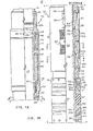
- FIGURES lA, B, and C are drawings, partially in section and partially in elevation, showing a hydraulic set packer of the present invention with the anchoring means and sealing unit in their first position as the packer is lowered into a casing string.
- FIGURES 2A, 2B, and 2C, partially in section and partially in elevation, show the hydraulic set packer with the anchoring means and the sealing unit in their second position forming a seal with the inner wall of the casing string.
- FIGURES 3A, 3B, and 3C, partially in section and partially in elevation, show the hydraulic set packer with the sealing unit in its third position as the packer is removed from a casing string.
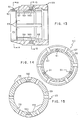
- FIGURE 4 is a cross section taken along line 4-4 of Figure lA.
- FIGURE 5 is a cross section taken along line 5-5 of Figure 1B showing the slip means in more detail.
- FIGURE 6 is a cross section taken along line 6-6 of Figure 1B showing the collet fingers and camming surfaces of the lower or second expander ring and the collet support ring.
- FIGURES 7, 8, 9, 10, 11, and 12 are schematic drawings, partially in section, showing various arrays of center elements, end elements, and backup rings or reinforcing discs which can be used on the sealing unit of the present invention.
- FIGURE 13 is an enlarged sectional view of the second or lower expander ring.
- FIGURE 14 is a cross section taken along line 14-14 of Figure 13.
- FIGURE 15 is a cross section taken along line 15-15 of Figure 13.
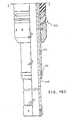
- FIGURES 16A, B, and C are drawings, partially in section and partially in elevation, showing a mechanically set packer of the present invention with the anchoring means and the sealing unit each in their first position.
- Referring to the drawings and particularly Figures 1A, 1B, and 1C, well
packer 20 is attached totubing string 21. Figures lA, 1B, and1C show packer 20 withsealing unit 30 and slip means 50 each in their respective first position. This is the normal condition in whichpacker 20 would appear prior to being installed in a well and while being lowered bytubing string 21 through the bore of a casing string. -
Packer 20 comprises a mandrel means 22 which has alongitudinal flow passage 23 therethrough.Longitudinal passage 23 is concentric with the bore oftubing 21 and communicates fluid from belowpacker 20 totubing 21. Mandrel means 22 includes anadapter sub 22a which hasthreads 24 formed on one end to provide a means for connectingpacker 20 totubing string 21. Various well tools or additional tubing could be attached to mandrel means 22 at itslower end 22b. - The major components of
packer 20 are generally cylindrical and carried on the exterior of mandrel means 22. Means for anchoringpacker 20 to the inner wall of a casing string includespiston housing 41 which is engaged bythreads 42 to the exterior ofadapter sub 22a.Lateral ports 43 andlongitudinal ports 44 formed inadapter sub 22a communicate fluid fromlongitudinal flow passage 23 to the interior ofpiston housing 41.Plugs 45 are threadedly engaged from the exterior ofadapter sub 22a intolateral ports 43.Plugs 45 provide means forflushing ports packer 20 is at the well surface. Whenplugs 45 are installed, they prevent fluid withinlongitudinal passage 23 from escaping to the exterior ofpacker 20. - Piston 46 is slidably disposed between
piston housing 41 and the exterior of mandrel means 22.Piston seals 47, carried on the end ofpiston 46, form a slidable fluid barrier. Variablevolume fluid chamber 48 is partially defined by the exterior of mandrel means 22, the inside diameter ofpiston housing 41, andpiston seals 47. Fluid pressure withinlongitudinal flow passage 23 can be communicated byports variable volume chamber 48 to movepiston 46 longitudinally with respect to mandrel means 22. As will be explained later, this movement ofpiston 46 causes slip means 50 to extend radially from mandrel means 22-anchoring packer 20 to the inner wall ofcasing 25. Since piston housing 4l:is engaged bythreads 42 toadapter sub 22a, the location-ofpiston housing 41 relative to mandrel means 22 remains fixed while running, setting, and pullingpacker 20. - The end of
piston 46opposite piston seals 47 is engaged byscrews 51 to upper or firstexpander ring 52.Shoulder 49, formed onpiston 46, abuts first expanderring 52. Slip means 50 is expanded radially by movingfirst expander ring 52 and second orlower expander ring 53 longitudinally towards each other. 'Each expander ring is generally cylindrical and carried on the exterior of mandrel means 22. Fourlugs 54 are threaded into holes in the outside diameter offirst expander ring 52. Guide lugs 54 onfirst expander ring 52 are spaced radially 90° from each other. Two lugs 54, spaced radially 180° from each other, are attached by threads to the exterior ofsecond expander ring 53. - Housing means 55 is generally a cylinder surrounding mandrel means 22. Expander rings 52 and 53 are partially disposed within the ends of
housing 55 between the exterior of mandrel means 22 and the inside of housing means 55.Longitudinal guide slots 56 are cut inhousing 55 near both ends thereof. Guide lugs 54 are slidably disposed withinslots 56.Lugs 54 andslots 56 provide a means for interconnectinghousing 55 and expander rings 52 and 53 and still allowing limited movement relative to each other. - Each expander ring has a tapered
camming surface 57 on the end adjacent to slipmeans 50. Frusto-conical surfaces 58 are formed on the inside diameter of slip means 50 near either end thereof. Camming surfaces 57 and frusto-conical surfaces 58 are generally matching. Therefore, movement of expander rings 52 and 53 towards each other causes camming surfaces 57 to act as wedges projecting slip means 50 radially from mandrel means 22. -
Lower expander ring 53 is best shown in Figures 13, 14, and 15.Camming surface 57 is formed on the exterior ofcollet fingers 59. The sixcollet fingers 59 can flex inwardly. Threadedholes 160 are machined in two opposingcollet fingers 59 forlugs 54 to be secured therein.Collet support ring 60 is shown secured by releasable means to the inside diameter ofcollet fingers 59. The releasable means comprises threeshear pins 61 spaced radially 120° connectingcollet support ring 60 to three of thecollet fingers 59. Alarge recess 62 is machined in the inside diameter ofsecond expander ring 53 to facilitate inward flexing ofcollet fingers 59. -
First expander ring 52 has an enlarged insidediameter 63 opposite a portion of itscamming surface 57.Shoulder 64 is formed by enlarged insidediameter 63. As will be explained later,shoulder 64 andcollet support ring 60 comprise apportion of the means for releasingpacker 20 from the inner wall ofcasing string 25. - Sealing
unit 30 is carried on the exterior of mandrel means 22 longitudinally adjacent tosecond expander ring 53. Sealingunit 30 comprises a first orupper support ring 31 which is releasably secured tomandrel 22 by shear screws 32. A second orlower support ring 34 is releasably secured to the exterior ofmandrel 22 and spaced longi- tudinally fromfirst support ring 31. Shear screws 35 releasablysecure support ring 34 to mandrel means 22. The first position of sealingunit 30 in which it is relaxed is defined byshear screws mandrel 22. - Various arrays of packing elements can be carried on the exterior of
mandrel 22 between support rings 31 and 34. The array shown in Figure 1B comprises metal backup rings ordiscs end elements center element 37. As will be explained later, various combinations of center and end elements have been found to provide a fluid tight seal under high pressure and temperature conditions. To provide for improved support of the packing elements, each support ring has aconcaved surface 38 facing a similarconvex surface 39 on the backup rings 33. :Sealingelement 30 is shown in Figure 1B in its first, relaxed position. - Referring generally to Figures 2A, 2B, and 2C,
packer 20 is shown anchored to the inner wall of casing 25 by slip means 50. Sealingunit 30 is shown in its second position forming a fluid tight seal betweencasing 25 and mandrel means 22; Thus, anyfluid entering casing 25 belowpacker 20 is directed by sealing unit.30 to flow to the well surface throughlongitudinal flow passage 23 andtubing string 21. In the same manner, if a high temperature fluid is injected from the well surface to an underground formation, sealingunit 30 prevents the high temperature fluid from contacting the inner wall of casing 25 abovepacker 20. - Setting tool JO is shown disposed within the upper portion of
longitudinal flow passage 23.Fishing neck 71 is provided on settingtool 70 so thattool 70 can be .raised and lowered by conventional wireline techniques throughtubing 21.Adapter sub 22a has a reduced insidediameter portion 72 which forms a tapered shoulder fortool 70 to rest on. 0-rings 76 are carried on the exterior oftool 70 and form a fluid tight seal with the inside diameter of mandrel means 22 whentool 70 is resting onshoulder 72. A valve means consisting ofvalve seat 73, valve disc 74, and valve stem 75 is contained withintool 70.Fishing neck 71 is attached to one end ofvalve stem 75 and valve disc 74 is attached to the other. Therefore, when fishingneck 71 is pulled upward, valve disc 74 is lifted fromvalve seat 73 opening a fluid passage through settingtool 70. The weight ofvalve stem 75 and disc 74 plus any difference in fluid pressure abovetool 70 as compared to belowtool 70 tends to close the valve means. Whentool 70 is resting on taperedshoulder 72, o-rings 76, disc 74, andseat 73 cooperate to prevent fluid abovetool 70 from flowing intolongitudinal flow passage 23 belowtool 70. -
Longitudinal slots 77 are machined in the circumference oftool 70 from the end opposite o-rings 76.Slots 77 connect withgroove 78 machined in the outside diameter oftool 70 intermediate the ends thereof.Slots 77 andgroove 78 are sized to allow fluid withintubing 21 to communicate withports tool 70 is resting onshoulder 72. An increase in fluid pressure withintubing 21 can thus be communicated to variablevolume fluid chamber 48. The increased fluid pressure causespiston 46- to move in one direction relative to mandrel means 22. - Internal slip means 80 are disposed between the inside diameter of
first expander ring 52 and the exterior of mandrel means 22. Internal slip means 80 consists of aring 81 with alongitudinal slot 82 formed therein. Anenlarged wedge 83 is formed on one end ofring 81.Spring 84 is disposed around the circumference ofring 81. One end ofspring 84 rests on the end ofpiston 46 and the other onwedge 83.Spring 84 biases internal slip means 80 in the one direction away frompiston 46.Guide screw 85 is secured to the inside diameter offirst expander ring 52 and rides inslot 82 to prevent rotation of slip means 80 relative toexpander ring 52. The exterior of mandrel means 22 in the vicinity of internal slip means 80 has arough surface 86 which is designed to engage matching teeth on the inside diameter ofwedge 83. Internal slip means 80 thus allowsexpander ring 52 to be moved in one direction bypiston 46. When the fluid pressure inchamber 48 is reduced,wedge 83 engagesrough surface 86 and preventsexpander ring 52 from moving in the other direction relative to mandrel means 22. - As previously noted, sealing
unit 30 comprises an array of packing elements carried betweenfirst support ring 31 andsecond support ring 34. Shear screws 32 provide a means for releasably securingsupport ring 31 to mandrel means 22. Shear screws 35 provide a means for releasably securingsupport ring 34 to mandrel means 22. Less force can be preselected to releasesupport ring 31 from mandrel means 22 as compared to supportring 34 by installingfewer screws 32 than screws 35. Alternatively, screws 32 can be selected from material having a lower shear value as compared to screws 35. - As best shown in Figures 2B and 2C, movement of
piston 46 in one direction relative to mandrel means 22 causes the upper and lower expander rings to move towards each other. Camming surfaces.57 cooperate to radially extend slip means 50 from mandrel means 22. Serrated,' diamond shapedteeth 90 are formed on the outside diameter of slip means 50 and engage the inside diameter ofcasing string 25. With the anchoring means in its second position as shown in Figure 2B,packer 20 resists movement in either direction within the bore ofcasing 25. - After
teeth 90 are set or engaged withcasing 25, increased fluid pressure withinchamber 48 will cause mandrel means 22 to continue in the one direction relative to internal slip means 80. This continued movement causes force to be applied toupper support ring 31 which abutslower expander ring 53. The pressure applied tovariable volume chamber 48 is preselected to causescrews 32 to shear into twoportions screws 35 are preselected to require more force before they will shear, the continued movement of mandrel means 22 in the one direction causessecond support ring 34 to move towardsfirst support ring 31. The movement of the support rings towards each other causes longitudinal compression and radial expansion of the packing elements. - As best shown in Figure 2C, sealing
unit 30 forms a fluid tight seal between mandrel means 22 andcasing 25.Center element 37 andend elements center element 37 is ethlene propylene-diene terpolymer, sometimes referred to as EPDM. The end elements preferably used with EPDM are made from vinylidene fluoride and/or hexafluoropropylene copolymer reinforced with wire mesh. Vinylidene fluoride is sometimes referred to as VITON and hexafluoropropylene is sometimes referred to as FLUOREL. VITON is a registered trademark belonging-to E. I. DuPont De Nemours & Co., Inc. FLUOREL is a registered trademark belonging to 3M Co. After some high temperature tests,center element 37 would still be in a liquid or near liquid state whenpacker 20 was removed from the test facility. However, sealingunit 30 withstood high differential pressures in either direction when end elements reinforced with wire mesh were used. As will be later explained, the geometry of the end elements 36 and metal backup rings 33 results in increasing the differential pressure capabilities of sealingunit 30 and allowing selective compression of the packing elements. - The present invention includes means for releasing
packer 20 from the. inner wall ofcasing string 25 by merely applying a preselected amount of upward tension totubing string 21. In Figures 3A, 3B, and 3C,packer 20 is shown being pulled from the casing (not shown) bytubing string 21. When a preselected amount of tension is applied totubing string 21, screws 35 will shear into twoportions means 50. Sealingunit 30 is also now free to slide over the exterior of mandrel means 22. - A
first shoulder 95 is formed on the exterior of mandrel means 22 adjacent slip means 50. Firstslip expander ring 52 has a partially enlarged insidediameter 63 which forms a matchingshoulder 64. When mandrel means 22 moves a preselected distance relative to slip means 50,first shoulder 95 will engagefirst expander ring 52 and pullcamming surface 57 from behind slip means 50. - A
second shoulder 97 is formed on the exterior of mandrel means 22 and spaced longitudinally fromfirst shoulder 95. When mandrel means 22 has moved a preselected distance relative to slip means 50,second shoulder 97 will movecollet support ring 60 from underneathcollet fingers 59.Collet fingers 59 can then flex inwardly releasingsecond expander ring 53 from behind slip means 50. - As shown in Figure 3B,
first expander ring 52 has been lifted byfirst shoulder 95 from behind slip means 50.Lugs 54 onexpander 52 are at the top ofguide slots 56a.Lower expander ring 53 has dropped from behind slip means 50.Lugs 54 onexpander ring 53 are resting at the bottom ofguide slots 56b. - Each slip means 50 is connected to the other by three
garter springs casing 25. The cross section of slip means 50 is generally rectangular with lips projecting from each end to retain slip means 50 withinhousing 55. - A
third shoulder 98 is formed nearend 22b of mandrel means 22.Second support ring 34 has a matchingshoulder 99 formed on its inside diameter. When screws 32 and 35 are sheared, sealingunit 30 can slide freely over the exterior of mandrel means 22.Third shoulder 98 provides a means for catching sealingunit 30 and preventing it from falling off whilepacker 20 is being removed from the casing. The third position for sealingunit 30 is defined when both shearscrews - As best shown in Figure 3A, longitudinal movement of mandrel means 22 in the one direction relative to slip means 50 results in
piston 46 and piston seals 47 becoming disengaged frompiston housing 41. Variablevolume fluid chamber 48 is now opened at one end which establishes a communication flow path throughports packer 20 andlongitudinal flow passage 23. Equalizing any difference in pressure is an important step in releasingpacker 20 fromcasing 25. - As previously mentioned,
packer 20 of the present invention is particularly adapted for use with high temper- - ature and pressure fluids.Center element 37 andend elements casing 25. Sealingunit 30 thus prevents the hot fluids from contacting the inner wall of casing 25 abovepacker 20.Variable volume chamber 48 is filled with fluid while settingpacker 20. This fluid withinchamber 48 acts as a buffer to protectpiston seals 47 from the hot, possibly corrosive fluids flowing throughlongitudinal flow passage 23. - One important feature of the present invention is that the packing elements of
seal unit 30 can be easily changed to form various arrays for use with different well fluids.Third shoulder 98 is preferably a c-ring or snap ring which can be quickly removed from an annular groove nearend 22b ofmandrel 22. Shear screws 35 can be removed allowingsecond support ring 34 to slide off mandrel means 22. Backup rings 33, end elements 36, andcenter element 37 are sized to be slidable over the exterior ofmandrel 22. - Figures 7-12 show various arrays of packing elements which can be satisfactorily used with
packer 20. The array shown in Figure 7 comprises acenter element 110 manufactured from ethlene propylene-diene terpolymer, sometimes referred to as EPDM.End elements 111 are preferably made from vinylidene fluoride (.VITON, a registered trademark belonging to DuPont) or hexafluoropropylene copolymer (FLUOREL, a registered trademark belonging to 3M Co.). End elements III are reinforced with wire mesh .005 inches in diameter and formed into a weave pattern .125 to .135 inches square. Six to twenty layers of the wire mesh are contained within eachend element 111. Metal backup rings 112 are added on either side ofend elements 111. Metal backup rings 112 minimize extrusion and loss of the elastomeric material when sealingunit 30 is compressed. - Figure 8 shows an
alternative end elements 113 made from asbestos rings reinforced with wire.End elements 113 also includes the unique cross section of the present invention when sealingunit 30 is.relaxed. The cross section ofend elements 113 is partially elliptical with the major axis of the ellipse slanted towards the centerline ofcenter element 110. The cross section ofend elements 113 is further defined by their inside and outside diameters being parallel cylindrical surfaces. As the packing array shown in Figure 8 compressed, the axis of the cross section ofend elements 113 will move towards a less acute angle. Also, backup rings 112 are concaved to match the exterior ofend elements 113. Metal backup rings 112 are flexible and will deform to maintain close contact withend elements 113 as the array is compressed. The combination of the unique cross section and matching concave, flexible backup rings results in first compressing the center element and then the end elements. - Another alternative array is shown in Figure 9. This array comprises a
center element 114 made from vinylidene fluoride or hexafluoropropylene copolymer. At high temperatures.these compounds exhibit characteristics of more conventional elastomers.End elements 115 are reinforced by wire .01 inches in diameter formed into a square mesh 0.18 to 0.25 inches on a side. Each element has 18 to 36 layers per section. Asbestos cord and/or ceramic fibers are dispersed throughout the wire mesh. - Figure 10 discloses another packing array having multiple end elements. Two rings 116 of virgin polytetra- .fluorethylene (commonly referred to as TEFLON, a registered. trademark belonging to DuPont) are disposed on either side of
center element 110. Two rings 117 of polyphenylene sulfide resin (commonly referred to as RYTON, a registered trademark belonging to Phillips Petroleum) are next positionedadjacent rings 116. - Figure 11 shows an array in which
center element 118 can be either the same ascenter elements End element 119 is preferably formed from laminated, ribbon packing made of carbon in the form of graphite.This packing is sometimes referred to as GRAFOIL,a registered trademark of Union Carbide Corporation and disclosed in U.S.Patent 3,404,061.
Carbon packing element 119 is reinforced with wire mesh. - Figure 12 shows the final array of the present invention comprising a
center element 120 made from the same material asring 116.End elements combination with'center element 120. - An alternative means for anchoring
packer 130 incorporating the present invention to the inner wall of a casing string is shown in Figures 16A, 16B, and 16C. Packers which are mechanically set by rotating tubing at the well surface are well known. U. S. Patent 3,385,366 discloses a packer which is mechanically set by J-slots engaging a lug, drag springs rubbing against the inner wall of a casing string, and rotating the tubing. U.S. Patent 3,385,366 is incorporated by reference for all purposes. - Mandrel means 22 is essentially the same in both
packer first expander ring 52 andthird shoulder 98 are identical and have been given the same number. Inpacker 130adapter sub 22c is used instead ofadapter sub 22a. -
Adapter sub 22c is attached to and forms a portion of mandrel means 22. The outside diameter ofadapter sub 22c has left-hand acme threads 131 formed thereon.Spring carrier 132 is rotatably secured to the exterior of mandrel means 22 by engagement withacme threads 131.Boss 133 is welded to the exterior ofadapter sub 22c and spaced longitudinally fromthreads 131.Boss 133 limits the longitudinal movement ofspring carrier 132 whencarrier 132 is rotated to the left with respect to mandrel means 22.Spring carrier 132 is generally cylindrical with three bow or drag springs 134 extending radially therefrom.Screws 135 are used to attach bow springs 134,carrier 132, andfirst expander ring 52 together.as a single rotating unit. Bow springs 134 are sized to rub against the inner wall of a casing string (not shown). When mandrel means 22 is rotated to the right, bow springs 134 limit the rotation ofcarrier 132 by dragging against the inner wall of the casing. Left-hand acme threads 131 thus causecarrier 132 andfirst expander ring 52 to move longitudinally in the one direction relative to mandrel means 22. This longitudinal movement results in expander rings 52 and 53 moving towards each other radially projecting slip means 50 and compressing sealingunit 30 as previously explained. - For
packer 130,rough surface 86 is preferably a triple left-hand thread having the same pitch asthreads 131. The teeth on the inside diameter ofwedge 83 are machined to matchrough surface 86. Therefore, internal slip means 80 will make one revolution around mandrel means 22 in unison withspring carrier 132. -
Top sub 136 is engaged by threads to adapter sub 22c. 0-ring sleeve 137 is secured on the inside diameter ofpacker 130 betweentop sub 136 andadapter sub 22c.Top sub 136 haslugs 138 which project into the bore ofpacker 130. - . The running tool used to install and set
packer 130 comprises J-slot mandrel 139 disposed within the bore oftop sub 136. J-slot mandrel 139 hasthreads 140 at one end for attachment to a tubing string (not shown). J-slot mandrel 139 is releasably secured totop sub 136 byshear sleeve 141 and shear screws 142. Shear sleeve l4l preventspacker 130 from disengaging from J-slot mandrel 139 while being installed in the casing.Shear sleeve 141 has aninternal shoulder 143 spaced longitudinally from a matching.shoulder 144 on the exterior of J-slot mandrel 139. The spacing betweenshoulders slot mandrel 139 relative totop sub 136 without shearing screws 142. J-slots 145 are machined in the exterior ofmandrel 139. J-slots 145 are sized for engagement withlugs 138. Rotation of tubing (not shown) connected bythreads 140 to J-slot mandrel 139 is transmitted to rotatetop sub 136 bylugs 138. -
Polished sleeve 146 is attached to the end of J-slot mandrel 139opposite threads 140. Preferably, the exterior ofpolished sleeve 146 has a smooth, honed surface to form a fluid tight seal with o-rings 147 on the inside diameter of o-ring sleeve 137. -
Packer 130 is attached to J-slot mandrel 139 as shown in Figure l6A and run into the bore of a casing string (not shown)by a tubing string (not shown) attached tothreads 140. Whenpacker 130 has been lowered to the desired depth intermediate the ends of the casing string, the tubing string is rotated to right. Rotation of the tubing string is transmitted to J-slot mandrel 139,top sub 136 bylugs 138, and mandrel means 22 byadapter sub 22c threadedly engaged withtop sub 136. Bow springs 134 drag against the inner wall of the pasing string minimizing rotation ofspring carrier 132. Sincespring carrier 132 does not rotate freely, left-hand acme threads 131cause spring carrier 132 to move in one direction longitudinally with respect to mandrel means 22. As previously explained forpacker 30, this longitudinal movement in one direction results infirst expander ring 52 moving towardssecond expander ring 53 to project slip means 50 radially from mandrel means 22. -
Threads 131 are preferably sized such that after fourteen turns to theright spring carrier 132 will be disengaged from mandrel means 22. As previously noted, threads formingrough surface 86 and threads on the inside diameter ofwedge 83 are matched allowing this rotation to simultaneously move internal slip means 80 in the one direction. - After slip means 50 initially engages the inner wall of the casing string, J-
slot mandrel 139 is lowered and rotated to the left toengage.lugs 138 in the short portion of J-slots 145. A preselected amount of tension is then applied to the tubing string and J-slot mandrel 139 to fully engage slip means 50 with the casing andplace sealing unit 30 in its second position. When the tension is released from J-slot mandrel 139, internal slip means 80 locks expander rings 52 and 53 in position relative to each other. Afterpacker 130 is set J-slot mandrel 139 is released fromlugs 138 and the tubing spaced out as required. - The foregoing description of the present invention is only an explanation of some of the preferred embodiments. Various changes and modifications will be readily apparent to those skilled in the art without departing from the ' scope of the invention which is defined in the claims.
Claims (6)
Applications Claiming Priority (2)
| Application Number | Priority Date | Filing Date | Title |
|---|---|---|---|
| US06/082,406 US4296806A (en) | 1979-10-05 | 1979-10-05 | High temperature well packer |
| US82406 | 1979-10-05 |
Related Parent Applications (2)
| Application Number | Title | Priority Date | Filing Date |
|---|---|---|---|
| EP80902084.5 Division | 1980-09-22 | ||
| EP19800902084 Division EP0036427A1 (en) | 1979-10-05 | 1980-09-22 | High temperature well packer |
Publications (2)
| Publication Number | Publication Date |
|---|---|
| EP0155413A2 true EP0155413A2 (en) | 1985-09-25 |
| EP0155413A3 EP0155413A3 (en) | 1987-08-19 |
Family
ID=22171004
Family Applications (3)
| Application Number | Title | Priority Date | Filing Date |
|---|---|---|---|
| EP84201962A Withdrawn EP0155413A3 (en) | 1979-10-05 | 1980-09-22 | High temperature well packer |
| EP19800902084 Pending EP0036427A1 (en) | 1979-10-05 | 1980-09-22 | High temperature well packer |
| EP84201961A Withdrawn EP0155412A3 (en) | 1979-10-05 | 1980-09-22 | High temperature well packer |
Family Applications After (2)
| Application Number | Title | Priority Date | Filing Date |
|---|---|---|---|
| EP19800902084 Pending EP0036427A1 (en) | 1979-10-05 | 1980-09-22 | High temperature well packer |
| EP84201961A Withdrawn EP0155412A3 (en) | 1979-10-05 | 1980-09-22 | High temperature well packer |
Country Status (8)
| Country | Link |
|---|---|
| US (1) | US4296806A (en) |
| EP (3) | EP0155413A3 (en) |
| JP (1) | JPS5922878B2 (en) |
| CA (1) | CA1140461A (en) |
| GB (4) | GB2071186B (en) |
| NO (1) | NO811897L (en) |
| SG (1) | SG60183G (en) |
| WO (1) | WO1981001028A1 (en) |
Families Citing this family (51)
| Publication number | Priority date | Publication date | Assignee | Title |
|---|---|---|---|---|
| US4336841A (en) * | 1980-11-17 | 1982-06-29 | Camco, Incorporated | Mechanical tubing anchor |
| US4375240A (en) * | 1980-12-08 | 1983-03-01 | Hughes Tool Company | Well packer |
| US4457369A (en) * | 1980-12-17 | 1984-07-03 | Otis Engineering Corporation | Packer for high temperature high pressure wells |
| US4573537A (en) * | 1981-05-07 | 1986-03-04 | L'garde, Inc. | Casing packer |
| US4615544A (en) * | 1982-02-16 | 1986-10-07 | Smith International, Inc. | Subsea wellhead system |
| US4441721A (en) * | 1982-05-06 | 1984-04-10 | Halliburton Company | High temperature packer with low temperature setting capabilities |
| US4531749A (en) * | 1983-06-02 | 1985-07-30 | Hughes Tool Company | Circular seal with integral backup rings |
| US4548265A (en) * | 1983-07-15 | 1985-10-22 | Baker Oil Tools, Inc. | Downhole steam packing |
| US4708202A (en) * | 1984-05-17 | 1987-11-24 | The Western Company Of North America | Drillable well-fluid flow control tool |
| US4588029A (en) * | 1984-09-27 | 1986-05-13 | Camco, Incorporated | Expandable metal seal for a well tool |
| US4750559A (en) * | 1985-05-28 | 1988-06-14 | Dresser Industries, Inc. | Retrievable anchor assembly |
| US4702313A (en) * | 1985-05-28 | 1987-10-27 | Dresser Industries, Inc. | Slip and slip assembly for well tools |
| US4660863A (en) * | 1985-07-24 | 1987-04-28 | A-Z International Tool Company | Casing patch seal |
| US4671354A (en) * | 1985-08-27 | 1987-06-09 | Otis Engineering Corporation | Well packer |
| US4665978A (en) * | 1985-12-19 | 1987-05-19 | Baker Oil Tools, Inc. | High temperature packer for well conduits |
| JPH0442462Y2 (en) * | 1986-01-27 | 1992-10-07 | ||
| US4688634A (en) * | 1986-01-31 | 1987-08-25 | Dresser Industries, Inc. | Running and setting tool for well packers |
| US4665977A (en) * | 1986-02-19 | 1987-05-19 | Baker Oil Tools, Inc. | Tension set seal bore packer |
| US6497416B1 (en) * | 1986-02-25 | 2002-12-24 | John D. Morvant | Wire inserted non-extrusion ring |
| US4688752A (en) * | 1986-04-25 | 1987-08-25 | Libbey-Owens-Ford Co. | Mold structure for producing an encapsulated window assembly |
| US4862967A (en) * | 1986-05-12 | 1989-09-05 | Baker Oil Tools, Inc. | Method of employing a coated elastomeric packing element |
| US4753444A (en) * | 1986-10-30 | 1988-06-28 | Otis Engineering Corporation | Seal and seal assembly for well tools |
| CA1292704C (en) * | 1987-04-07 | 1991-12-03 | Douglas C. Campbell | Pipeline packer |
| US4811959A (en) * | 1987-11-27 | 1989-03-14 | Otis Engineering Corporation | Seal assembly for well locking mandrel |
| US5303936A (en) * | 1989-12-28 | 1994-04-19 | Nok Corporation | Seal ring |
| US5113939A (en) * | 1990-03-09 | 1992-05-19 | Otis Engineering Corporation | Single bore packer with dual flow conversion for gas lift completion |
| US5165703A (en) * | 1991-03-20 | 1992-11-24 | Oem Components, Inc. | Anti-extrusion centering seals and packings |
| US5199497A (en) * | 1992-02-14 | 1993-04-06 | Baker Hughes Incorporated | Shape-memory actuator for use in subterranean wells |
| GB2291450B (en) * | 1992-05-15 | 1996-04-03 | Halliburton Co | Retrievable well packer |
| US5311938A (en) * | 1992-05-15 | 1994-05-17 | Halliburton Company | Retrievable packer for high temperature, high pressure service |
| US6062570A (en) * | 1996-02-16 | 2000-05-16 | Barber-Colman | Stem sealing system for broad temperature ranges |
| US6142226A (en) * | 1998-09-08 | 2000-11-07 | Halliburton Energy Services, Inc. | Hydraulic setting tool |
| US6530574B1 (en) | 2000-10-06 | 2003-03-11 | Gary L. Bailey | Method and apparatus for expansion sealing concentric tubular structures |
| US7419001B2 (en) | 2005-05-18 | 2008-09-02 | Azura Energy Systems, Inc. | Universal tubing hanger suspension assembly and well completion system and method of using same |
| US8286713B2 (en) * | 2005-05-18 | 2012-10-16 | Argus Subsea, Inc. | Oil and gas well completion system and method of installation |
| US7708080B2 (en) * | 2005-06-23 | 2010-05-04 | Schlumberger Technology Corporation | Packer |
| US7422058B2 (en) * | 2005-07-22 | 2008-09-09 | Baker Hughes Incorporated | Reinforced open-hole zonal isolation packer and method of use |
| US7780173B2 (en) * | 2007-03-12 | 2010-08-24 | Tyco Electronics Corporation | Sealing assemblies and methods for sealing an elongate member |
| US7905492B2 (en) * | 2007-12-03 | 2011-03-15 | Baker Hughes Incorporated | Self-boosting wedge tubing-to-casing seal |
| US7753131B2 (en) * | 2008-08-20 | 2010-07-13 | Tam International, Inc. | High temperature packer and method |
| US8104769B2 (en) * | 2008-12-17 | 2012-01-31 | Seal Science & Technology, Llc | Bi-directional wellhead seal |
| GB2469870A (en) * | 2009-05-01 | 2010-11-03 | Swelltec Ltd | Support assembly for a downhole tool |
| CA2674823C (en) * | 2009-08-05 | 2011-09-20 | Schlumberger Canada Limited | Hydraulic packer with thermal isolation member |
| US8464786B2 (en) * | 2010-07-20 | 2013-06-18 | Schlumberger Technology Corporation | Non basepipe-welded accessory attachment |
| US20120255723A1 (en) * | 2011-04-05 | 2012-10-11 | Halliburton Energy Services, Inc. | Drillable slip with non-continuous outer diameter |
| CN103104213B (en) * | 2012-12-14 | 2016-01-13 | 中国石油集团川庆钻探工程有限公司 | HTHP test packer |
| CN103225490B (en) * | 2013-04-11 | 2015-08-05 | 中国石油天然气股份有限公司 | Minor diameter double containment Delaminated steam injecting packer |
| CN110388191A (en) * | 2019-04-04 | 2019-10-29 | 上海优强石油科技有限公司 | The packing element support device of big expanding open hole well packer |
| EP3994333A4 (en) * | 2019-07-02 | 2023-02-08 | Services Pétroliers Schlumberger | Expanding and collapsing apparatus with seal pressure equalization |
| MX2022000750A (en) * | 2019-07-18 | 2022-02-14 | Schlumberger Technology Bv | Port free hydraulic unibody system and methodology for use in a well. |
| CN112554838B (en) * | 2020-12-11 | 2023-03-31 | 惟其信石油机械(天津)有限公司 | High-temperature and high-pressure resistant packer |
Citations (8)
| Publication number | Priority date | Publication date | Assignee | Title |
|---|---|---|---|---|
| US2715442A (en) * | 1951-11-26 | 1955-08-16 | Cicero C Brown | Well packers |
| US3142339A (en) * | 1958-06-30 | 1964-07-28 | Brown Oil Tools | Hydraulically-actuated well packers |
| US3215205A (en) * | 1961-03-31 | 1965-11-02 | Otis Eng Co | Retrievable hydraulic set well packers |
| US3330357A (en) * | 1964-08-26 | 1967-07-11 | Otis Eng Co | Mechanically set high temperature well packer |
| US3331440A (en) * | 1965-04-16 | 1967-07-18 | Brown Oil Tools | Well packer |
| US3391742A (en) * | 1966-05-27 | 1968-07-09 | Brown Oil Tools | Releasable well packer |
| US3391740A (en) * | 1965-07-28 | 1968-07-09 | Brown Oil Tools | Hydraulically set retrievable well tool |
| US3976133A (en) * | 1975-02-05 | 1976-08-24 | Brown Oil Tools, Inc. | Retrievable well packer |
Family Cites Families (14)
| Publication number | Priority date | Publication date | Assignee | Title |
|---|---|---|---|---|
| US2143106A (en) * | 1937-03-08 | 1939-01-10 | Dayton Rubber Mfg Co | Oil packer |
| US2430623A (en) * | 1942-03-19 | 1947-11-11 | Guiberson Corp | Control head packer |
| US2638168A (en) * | 1948-07-31 | 1953-05-12 | Asbury S Parks | Well packer |
| US2546950A (en) * | 1949-04-22 | 1951-03-27 | Wilson Foundry & Machine Compa | Tubing anchor |
| US2696886A (en) * | 1950-09-16 | 1954-12-14 | Ware Cecil | Casing bridging plug |
| US2901044A (en) * | 1955-07-07 | 1959-08-25 | Edward W Arnold | Pulling tool |
| GB991581A (en) * | 1962-03-21 | 1965-05-12 | High Temperature Materials Inc | Expanded pyrolytic graphite and process for producing the same |
| US3381969A (en) * | 1965-02-01 | 1968-05-07 | Dresser Ind | Thermal packer construction |
| US3385366A (en) * | 1966-01-06 | 1968-05-28 | Otis Eng Co | Retrievable well packer |
| US3464709A (en) * | 1966-05-20 | 1969-09-02 | Us Industries Inc | Laminated packer |
| US4050517A (en) * | 1976-10-14 | 1977-09-27 | Sperry Rand Corporation | Geothermal energy well casing seal and method of installation |
| US4146093A (en) * | 1977-01-21 | 1979-03-27 | Koolaj-Es Foldgazbanyaszati Ipari Kutato Laboratorium | Layer-separating device hydraulically anchorable in a well casing |
| US4131160A (en) * | 1977-07-25 | 1978-12-26 | Brown Oil Tools, Inc. | Well tool with pressure responsive tightening means |
| US4176715A (en) * | 1977-12-23 | 1979-12-04 | Baker International Corporation | High temperature well packer |
-
1979
- 1979-10-05 US US06/082,406 patent/US4296806A/en not_active Expired - Lifetime
-
1980
- 1980-09-16 CA CA000360281A patent/CA1140461A/en not_active Expired
- 1980-09-22 GB GB8114515A patent/GB2071186B/en not_active Expired
- 1980-09-22 JP JP55502505A patent/JPS5922878B2/en not_active Expired
- 1980-09-22 WO PCT/US1980/001221 patent/WO1981001028A1/en not_active Application Discontinuation
- 1980-09-22 EP EP84201962A patent/EP0155413A3/en not_active Withdrawn
- 1980-09-22 EP EP19800902084 patent/EP0036427A1/en active Pending
- 1980-09-22 EP EP84201961A patent/EP0155412A3/en not_active Withdrawn
-
1981
- 1981-06-04 NO NO811897A patent/NO811897L/en unknown
-
1982
- 1982-09-15 GB GB08226246A patent/GB2107763A/en not_active Withdrawn
- 1982-09-15 GB GB08226245A patent/GB2107762B/en not_active Expired
- 1982-09-15 GB GB08226244A patent/GB2107761B/en not_active Expired
-
1983
- 1983-09-23 SG SG60183A patent/SG60183G/en unknown
Patent Citations (8)
| Publication number | Priority date | Publication date | Assignee | Title |
|---|---|---|---|---|
| US2715442A (en) * | 1951-11-26 | 1955-08-16 | Cicero C Brown | Well packers |
| US3142339A (en) * | 1958-06-30 | 1964-07-28 | Brown Oil Tools | Hydraulically-actuated well packers |
| US3215205A (en) * | 1961-03-31 | 1965-11-02 | Otis Eng Co | Retrievable hydraulic set well packers |
| US3330357A (en) * | 1964-08-26 | 1967-07-11 | Otis Eng Co | Mechanically set high temperature well packer |
| US3331440A (en) * | 1965-04-16 | 1967-07-18 | Brown Oil Tools | Well packer |
| US3391740A (en) * | 1965-07-28 | 1968-07-09 | Brown Oil Tools | Hydraulically set retrievable well tool |
| US3391742A (en) * | 1966-05-27 | 1968-07-09 | Brown Oil Tools | Releasable well packer |
| US3976133A (en) * | 1975-02-05 | 1976-08-24 | Brown Oil Tools, Inc. | Retrievable well packer |
Also Published As
| Publication number | Publication date |
|---|---|
| JPS5922878B2 (en) | 1984-05-29 |
| EP0155413A3 (en) | 1987-08-19 |
| GB2107762B (en) | 1983-12-14 |
| GB2107761A (en) | 1983-05-05 |
| GB2107762A (en) | 1983-05-05 |
| GB2071186B (en) | 1983-05-18 |
| GB2071186A (en) | 1981-09-16 |
| EP0036427A1 (en) | 1981-09-30 |
| CA1140461A (en) | 1983-02-01 |
| JPS56501412A (en) | 1981-10-01 |
| NO811897L (en) | 1981-06-04 |
| SG60183G (en) | 1984-07-27 |
| US4296806A (en) | 1981-10-27 |
| WO1981001028A1 (en) | 1981-04-16 |
| GB2107763A (en) | 1983-05-05 |
| EP0155412A2 (en) | 1985-09-25 |
| EP0155412A3 (en) | 1987-08-12 |
| GB2107761B (en) | 1983-11-30 |
Similar Documents
| Publication | Publication Date | Title |
|---|---|---|
| US4296806A (en) | High temperature well packer | |
| USRE31933E (en) | High temperature well packer | |
| CA2199232C (en) | High temperature, high pressure retrievable packer | |
| US4524825A (en) | Well packer | |
| US5163514A (en) | Blowout preventer isolation test tool | |
| US4540053A (en) | Breech block hanger support well completion method | |
| US4898239A (en) | Retrievable bridge plug | |
| US4612985A (en) | Seal assembly for well tools | |
| US4411435A (en) | Seal assembly with energizing mechanism | |
| US4627491A (en) | Well packer | |
| US3361207A (en) | Retrievable subsurface well tools | |
| US4473122A (en) | Downhole safety system for use while servicing wells | |
| EP0190864B1 (en) | Pressure-responsive downhole well tool | |
| US3094169A (en) | Retrievable packer | |
| US5127476A (en) | Lockout housing and sleeve for safety valve | |
| US3695352A (en) | Retrievable well packer apparatus | |
| US3508610A (en) | Retrievable well packer apparatus | |
| GB2114631A (en) | Breech block hanger support | |
| US4388970A (en) | Apparatus and method for controlling injection fluid flow in a well annulus | |
| EP0349335B1 (en) | Plug for a gravel packer | |
| US3802505A (en) | Latching apparatus for installing safety valves or the like in wells | |
| US3858648A (en) | Dual string hydraulically actuated oil well packer | |
| CA1250520A (en) | Dual string tension - set, tension-release well packer | |
| CA1147645A (en) | High temperature well packer | |
| US3483921A (en) | Well packer having a selectively positionable valve means |
Legal Events
| Date | Code | Title | Description |
|---|---|---|---|
| PUAI | Public reference made under article 153(3) epc to a published international application that has entered the european phase |
Free format text: ORIGINAL CODE: 0009012 |
|
| 17P | Request for examination filed |
Effective date: 19841220 |
|
| AC | Divisional application: reference to earlier application |
Ref document number: 36427 Country of ref document: EP |
|
| AK | Designated contracting states |
Designated state(s): FR |
|
| RAP1 | Party data changed (applicant data changed or rights of an application transferred) |
Owner name: OTIS ENGINEERING CORPORATION |
|
| RAP1 | Party data changed (applicant data changed or rights of an application transferred) |
Owner name: OTIS ENGINEERING CORPORATION |
|
| PUAL | Search report despatched |
Free format text: ORIGINAL CODE: 0009013 |
|
| STAA | Information on the status of an ep patent application or granted ep patent |
Free format text: STATUS: THE APPLICATION HAS BEEN WITHDRAWN |
|
| AK | Designated contracting states |
Kind code of ref document: A3 Designated state(s): FR |
|
| 18W | Application withdrawn |
Withdrawal date: 19870721 |
|
| RIN1 | Information on inventor provided before grant (corrected) |
Inventor name: BOSTOCK, JAMES H. Inventor name: TAYLOR, DONALD F. |