EP0155270B1 - Acoustic position sensing apparatus - Google Patents
Acoustic position sensing apparatus Download PDFInfo
- Publication number
- EP0155270B1 EP0155270B1 EP84901508A EP84901508A EP0155270B1 EP 0155270 B1 EP0155270 B1 EP 0155270B1 EP 84901508 A EP84901508 A EP 84901508A EP 84901508 A EP84901508 A EP 84901508A EP 0155270 B1 EP0155270 B1 EP 0155270B1
- Authority
- EP
- European Patent Office
- Prior art keywords
- acoustic
- sensing
- transducer
- sheet
- film
- Prior art date
- Legal status (The legal status is an assumption and is not a legal conclusion. Google has not performed a legal analysis and makes no representation as to the accuracy of the status listed.)
- Expired
Links
- 239000000463 material Substances 0.000 claims abstract description 40
- 239000002033 PVDF binder Substances 0.000 claims description 6
- 229920002981 polyvinylidene fluoride Polymers 0.000 claims description 4
- 238000000059 patterning Methods 0.000 abstract description 2
- 239000004020 conductor Substances 0.000 description 9
- 239000000853 adhesive Substances 0.000 description 5
- 230000001070 adhesive effect Effects 0.000 description 5
- 230000006870 function Effects 0.000 description 5
- VVQNEPGJFQJSBK-UHFFFAOYSA-N Methyl methacrylate Chemical compound COC(=O)C(C)=C VVQNEPGJFQJSBK-UHFFFAOYSA-N 0.000 description 2
- 229910052782 aluminium Inorganic materials 0.000 description 2
- XAGFODPZIPBFFR-UHFFFAOYSA-N aluminium Chemical compound [Al] XAGFODPZIPBFFR-UHFFFAOYSA-N 0.000 description 2
- 238000010586 diagram Methods 0.000 description 2
- 238000005553 drilling Methods 0.000 description 2
- 229920003023 plastic Polymers 0.000 description 2
- 239000004033 plastic Substances 0.000 description 2
- 230000001681 protective effect Effects 0.000 description 2
- 125000006850 spacer group Chemical class 0.000 description 2
- 229920005372 Plexiglas® Polymers 0.000 description 1
- 230000001154 acute effect Effects 0.000 description 1
- 238000010276 construction Methods 0.000 description 1
- 230000008878 coupling Effects 0.000 description 1
- 238000010168 coupling process Methods 0.000 description 1
- 238000005859 coupling reaction Methods 0.000 description 1
- 230000000994 depressogenic effect Effects 0.000 description 1
- 238000001514 detection method Methods 0.000 description 1
- 239000006260 foam Substances 0.000 description 1
- 238000002347 injection Methods 0.000 description 1
- 239000007924 injection Substances 0.000 description 1
- 238000004519 manufacturing process Methods 0.000 description 1
- 238000005259 measurement Methods 0.000 description 1
- 229910052751 metal Inorganic materials 0.000 description 1
- 239000002184 metal Substances 0.000 description 1
- 239000002991 molded plastic Substances 0.000 description 1
- 230000002093 peripheral effect Effects 0.000 description 1
- 230000005236 sound signal Effects 0.000 description 1
Images


Classifications
-
- G—PHYSICS
- G01—MEASURING; TESTING
- G01B—MEASURING LENGTH, THICKNESS OR SIMILAR LINEAR DIMENSIONS; MEASURING ANGLES; MEASURING AREAS; MEASURING IRREGULARITIES OF SURFACES OR CONTOURS
- G01B17/00—Measuring arrangements characterised by the use of infrasonic, sonic or ultrasonic vibrations
-
- G—PHYSICS
- G03—PHOTOGRAPHY; CINEMATOGRAPHY; ANALOGOUS TECHNIQUES USING WAVES OTHER THAN OPTICAL WAVES; ELECTROGRAPHY; HOLOGRAPHY
- G03B—APPARATUS OR ARRANGEMENTS FOR TAKING PHOTOGRAPHS OR FOR PROJECTING OR VIEWING THEM; APPARATUS OR ARRANGEMENTS EMPLOYING ANALOGOUS TECHNIQUES USING WAVES OTHER THAN OPTICAL WAVES; ACCESSORIES THEREFOR
- G03B7/00—Control of exposure by setting shutters, diaphragms or filters, separately or conjointly
- G03B7/24—Control of exposure by setting shutters, diaphragms or filters, separately or conjointly automatically in accordance with markings or other means indicating film speed or kind of film on the magazine to be inserted in the camera
-
- Y—GENERAL TAGGING OF NEW TECHNOLOGICAL DEVELOPMENTS; GENERAL TAGGING OF CROSS-SECTIONAL TECHNOLOGIES SPANNING OVER SEVERAL SECTIONS OF THE IPC; TECHNICAL SUBJECTS COVERED BY FORMER USPC CROSS-REFERENCE ART COLLECTIONS [XRACs] AND DIGESTS
- Y10—TECHNICAL SUBJECTS COVERED BY FORMER USPC
- Y10S—TECHNICAL SUBJECTS COVERED BY FORMER USPC CROSS-REFERENCE ART COLLECTIONS [XRACs] AND DIGESTS
- Y10S310/00—Electrical generator or motor structure
- Y10S310/80—Piezoelectric polymers, e.g. PVDF
Definitions
- the invention relates to acoustic position sensing apparatus of the type for sensing the position of an object with respect to a sensing port in an acoustic resonator.
- Position sensors for producing an electronic signal representing the position of an object are essential parts of many complex electromechanical devices.
- the position sensing apparatus includes a "Y" shaped tube for defining an acoustic resonator.
- a first acoustic transducer e.g. a loud speaker
- the stem of the "Y" shaped tube is open, to define a sensing port.
- the resonant frequency of the acoustic resonator varies as a function of the position of an object near the sensing port.
- a second acoustic transducer e.g. a microphone
- the signal produced by the second acoustic transducer will be a maximum when the sensing port is completely unobstructed (open tube resonance), or completely covered (closed tube resonance).
- the acoustic transducers comprise acoustic transducers of the type used in hearing aids.
- a problem encountered in employing such prior art acoustic position sensors in small, mass-produced apparatus such as photographic cameras is the difficulty in mass-producing the acoustic transducers and incorporating the transducers in small areas, due to their physical size and complexity.
- the object of the invention is to provide acoustic position sensing apparatus that is simply constructed, that has improved mass-productivity, and is easily miniaturized for employment in compact, mass-produced apparatus.
- a further object of the invention is to provide an acoustic film position sensor for a photographic camera.
- a still further object is to provide an acoustic film cartridge feature sensor for a photographic camera.
- acoustic position sensing apparatus having acoustic transducers comprising a sheet of suitably poled piezoelectric material (preferably polymeric material such as polyvinylidene fluoride) having electrodes on opposite sides thereof.
- the sheet is fixed over a transducer port(s) in an acoustic resonator.
- a plurality of acoustic transducers are integrated on a single sheet of piezoelectric material by patterning the electrodes thereon.
- the acoustic resonator comprises a body of material having a pair of spaced- apart cylindrical holes through the thickness of the material.
- the holes converge near one side of the body to define a V-shaped cavity.
- the vertex of the V opens onto one surface of the body to form a sensing port.
- the legs of the V open on an opposite surface of the body to form transducer ports.
- the acoustic transducers are formed side- by-side on the sheet of polymeric piezoelectric material, such that when the sheet is fixed to the surface of the body having the transducer ports, one acoustic transducer is positioned over each transducer port.
- the acoustic resonator is defined by a cylindrical hole through the thickness of a body of material. One end of the hole defines the sensing port, and both acoustic transducers are fixed over the other end of the cylindrical hole, one on top of the other.
- the acoustic position sensing apparatus is employed in a photographic camera, and the acoustic transducers for: (1) an acoustic film notch sensor; (2) a plurality of cartridge notch sensors; and (3) an audio signal emitter are integrated on a single sheet of polymeric piezoelectric material.
- the use of the acoustic position sensing apparatus in a photographic camera has the advantage that the acoustic signal used to sense film features, or camera part position does not expose film, or damage sensitive film surfaces by mechanical contact.
- the acoustic position sensing apparatus is configured for detecting perforations 12 in a strip of film 14.
- the apparatus comprises a body of material 16 (e.g. plastic or metal) defining a film guide slot 18 and an acoustic resonator 20.
- the acoustic resonator is defined by a pair of cylindrical holes which converge to meet at a vertex to define a V-shaped cavity, with a sensing port 22 at the vertex of the V, opening into the film guide slot, and a pair of transducer ports 24 and 26 at the ends of the arms of the V.
- a sheet 28 of poled piezoelectric material preferably a polymeric piezoelectric material such as polyvinylidene fluoride (PVF 2 ) comprises the acoustic transducers of the acoustic position sensing apparatus.
- the acoustic transducers are fixed over the transducer ports 24 and 26, for example by an adhesive.
- FIG. 2 shows a plan view of the sheet of piezoelectric material 28.
- Two regions of the sheet of material are electrically addressable by means of a pair of patterned electrodes 30 and 32 on the top of the sheet, and an unpatterned electrode (not shown) on the bottom of the sheet.
- the regions of the sheet 28 beneath the patterned electrodes are rendered piezoelectrically active (poled) by applying a high voltage to the electrodes for a predetermined time at a predetermined temperature as is well known in the art. Alternatively, the entire sheet is poled prior to forming the patterned electrodes.
- the sheet of piezoelectric material 28 is fixed over the transducer ports 24 and 26 of the acoustic resonator 20 so that the regions of the sheet covered by the patterned electrodes are positioned over the ports.
- a corner 34 of the sheet is folded over and fixed with adhesive as shown in FIG. 1, to allow contact to be made to the backside electrode.
- a conductive cover 36 is placed over the transducers.
- a pair of coaxial connectors 38 and 40 are mounted in the sides of the cover 36. The cover itself, the ground leads of the coaxial connectors, and the backside electrode of sheet 28 are grounded, thereby providing electromagnetic interference shielding for the acoustic transducers.
- Electrode 30 is connected to an acoustic frequency generator 42 through connector 38.
- Electrode 32 is connected to an amplifier 44 through connector 40.
- Directly opposite sensing port 22 is a back cavity 46, formed by a cylindrical hole covered on one end by a piece of tape 48.
- an acoustic signal is applied by oscillator 42 to electrode 30 thereby causing the piezoelectrically active region under electrode 30 to vibrate over transducer port 24 to generate an acoustic signal in the acoustic resonator 20.
- the acoustic signal in acoustic resonator 20 is sensed by the piezoelectrically active region of sheet 28 fixed over transducer port 26 thereby generating an electrical signal proportional to the strength of the acoustic signal in acoustic resonator 20, on electrode 32.
- the signal on electrode 32 is amplified by amplifier 44.
- the resonant frequency of the acoustic resonator is a function of the extent to which sensing port 22 is covered or uncovered.
- the frequency of the acoustic signal is chosen to coincide with the resonant frequency of the acoustic resonator when the sensing port is covered.
- the frequency of the acoustic signal is chosen to coincide with the resonant frequency of the acoustic resonator when the sensing port is uncovered.
- the output of amplifier 44 is a function of the position of a film perforation 12 with respect to sensing port 22.
- the acoustic position sensing apparatus described above was constructed by drilling a pair of 1 mm diameter holes at 45° angles to define a V-shaped cavity in an 8.5 mm thick sheet of plexi-glass.
- the polymeric piezoelectric sheet was 25 um thick, biaxially stretched, PVF 2 with .1 pm thick aluminum electrodes vapor deposited through a mask.
- the diameters of the top electrodes 30 and 32 were 3 mm.
- the resonant frequency of the open cavity, i.e. with a perforation present, was 14.7 kHz.
- the resonant frequency was determined by varying the frequency of oscillator 42 until a maximum signal was detected on electrode 32.
- a 14.7 kHz, 10 volt square wave was applied to electrode 30 by oscillator 42.
- acoustic position sensing apparatus may also be used as an edge detector, a distance sensor, or a non-contact thickness guage.
- the thickness gauge is achieved by placing an acoustic position sensor on both sides of a sheet of material and observing the difference in the signals from the two sensors. If the output of amplifier 44 is applied to a trigger circuit such as a Schmidt trigger, the output of the apparatus becomes a logical binary signal, suitable for use for example as a noncontact switch to indicate the presence or absence of an object covering the sensing port.
- FIG. 3 shows an alternative embodiment of acoustic position sensing apparatus where elements analogous to elements in FIG. 1 are similarly numbered, with primes (').
- the regions of the sheet of piezoelectric material 28' covered by patterned electrodes, comprising the acoustic transducers, are stacked over a single transducer port 24' in the acoustic resonator 20', thereby further simplifying the construction of the device and reducing its size.
- FIG. 4 shows the electrode pattern on one side of the sheet 28' of piezoelectric material. The other side of the sheet is fully covered by an electrode.
- the sheet 28' is divided, as shown by phantom lines 50, 52, and 54, into four leaves 56, 58, 60, and 62.
- a hole 64 having substantially the same diameter as transducer port 24' is formed in leaf 56.
- An electrode 32' is formed on leaf 58; an electrode 30' is formed on leaf 60.
- Electrode 30' includes a conductor leg 30a' that extends onto leaf 58 from leaf 60.
- leaf 56 When assembled, leaf 56 is folded back and down (as seen in FIG. 4) along line 50 so that hole 64 is substantially aligned with the center of electrode 32'.
- leaf 60 is folded back and up along line 52 so that electrodes 30' and 32' are in substantial alignment.
- electrode 32', conductor leg 30a', and the backside electrode on flap 62 are all accessible from the same side of the stack.
- adhesive is used to hold the contacting surfaces together.
- Leaf 56 with hole 64 forms an air gap between the two transducer regions of the sheet, thereby improving the acoustic coupling between these regions.
- the apparatus has been found to work without this spacer, but operation is improved by its presence.
- Electrode 30' is on the bottom in contact with the top surface of block 16'. Electrode 32', a portion of the backside electrode, and conductor extension 30a' of electrode 30' are exposed for making electrical connections. Electrode 30' is connected to the acoustic frequency generator 42' via coaxial connector 38'. The backside electrode is connected to ground through the grounded side of coaxial connector 38', and electrode 32' is connected to amplifier 44' through coaxial connector 40'.
- the acoustic resonator was constructed by drilling a 1 mm diameter hole perpendicularly through the thickness of an 8.5 mm thick piece of plexiglass.
- a sine wave generator was connected to the bottom electrode 30', open tube resonances were observed at 7.57 kHz and 19.7 kHz, and a closed tube resonance was observed at 12.5 kHz.
- a 23 volt sine wave input having a frequency of 7.57 kHz was applied to the bottom electrode, and the observed input to the sensing amplifier 44' was 1.8 mV with no film present (i.e. at a perforation), and .9 mV amplifier input was observed with film present at the sensing port 22'.
- the amplifier input observed was .9 mV with no film present, and 1.9 mV with film present.
- the amplifier input was 2.1 mV with no film present, and 1.1 mV with film present.
- the approximately 2:1 on/off ratios observed with the device make object position detection accurate and reliable.
- FIG. 5 shows a further alternative embodiment of the acoustic position sensing apparatus having a stacked, folded acoustic transducer structure, further simplified by integrating an electromagnetic interference shield into the folded sheet structure.
- Elements of the device shown in FIG. 5 analogous to the previously described devices are similarly numbered with double primes (").
- FIG. 6 illustrates the electrode pattern on the sheet of piezoelectric material 28".
- the sheet is divided by phantom fold lines 50", 52", and 54" into four leaves 56", 58", 60", and 62".
- Leaf 56" is provided with a central aperture 64" substantially the same size as transducer port 24" in acoustic resonator 20" (see FIG. 5).
- Leaf 58" carries an electrode 30" having a conductor extension 30a” that extends slightly across fold line 52" onto leaf 60".
- leaf 60" carries an electrode 32" having a conductor extension 32a” that extends slightly across fold line 52" onto leaf 58".
- Leaf 62" is substantially narrower than leaves 58" and 60" and is provided with a tab 66, the purpose of which is explained below.
- the backside of sheet 28" is covered by one substantially unpatterned electrode.
- leaf 56" is folded back and to the right, as seen in FIG. 6, so that hole 64" is in substantial alignment with the center of electrode 30".
- Leaf 58" is then folded back and to the right along fold line 52" so that the electrodes 30" and 32" are in substantial alignment, with hole 64" in between them.
- leaf 62" is folded forward and to the left along line 54".
- tab 66 is folded around the edge at fold line 52".
- conductor extensions 30a" and 32a" are electrically accessible by a flat cable connector 68 (see FIG. 5) along fold line 52".
- Tab 66 is folded over fold line 52" as shown in FIG. 5, to provide electrical access to the unpatterned backside electrode.
- Connector 68 is provided with spring loaded contacts 70 in a known manner to make electrical contact with the extensions 30a" and 32a" of the patterned electrodes, and the unpatterned backside electrode.
- Electrode 30 is connected via one conductor in a flat, multiple-conductor cable 72 to acoustic generator 42". Electrode 32" is connected via cable 72 to amplifier 44".
- a Schmidt trigger 71 is shown connected to the output of amplifier 44".
- the trigger levels of the Schmidt trigger 71 are set to be between the respective outputs of amplifier, 44" when sensing port 22" is fully covered, and when it is fully uncovered.
- the arrangement shown in FIG. 5 is particularly well adapted for use as a touch-sensitive switch, for example.
- Mass-productivity of the acoustic position sensor is further improved by integrating a number of acoustic transducers on a single sheet of polymeric piezoelectric material.
- a rectangular or linear array of touch-sensitive switches employing the type of acoustic position sensor shown in FIG. 5 is made by appropriately repeating the electrode patterns shown in FIG. 6 and providing a body of material defining a number of acoustic resonators.
- FIG. 7 illustrates the acoustic position sensing apparatus employed in a photographic camera of the type adapted to expose disc film.
- a camera, generally designated 100 has a hinged film loading door 102 (partially shown in FIG. 7) that swings open to reveal a chamber 104 for receiving a disc film cartridge.
- a plan view of a disc film cartridge is shown in FIG. 8.
- the film cartridge 106 includes a protective housing 108 having an exposure window (not shown) located on the opposite side of the housing from a pressure pad area 110.
- a film drive hub 112 having a keyed aperture 114 is accessible from outside the cartridge for rotating a film disc inside the cartridge to bring successive exposure areas on the film disc into the exposure window.
- a vane 116 extending from protective housing 108 serves as a film speed indicator.
- the film chamber in the camera includes a film drive spindle 120, a cartridge opening lever 122, and a lens block 124 adapted to project into the exposure window of the film cartridge to define the film plane of the camera.
- a camera latch lever 126 swings in a counterclockwise arc in the direction of arrow A to latch the door closed.
- the camera latch lever 126 is connected to cartridge opening lever 122 and moves the cartridge opening lever to uncover the exposure window in the cartridge after the film loading door is closed.
- the lens block 124 extends into the exposure window to contact the film disc in the cartridge.
- Film frames around the periphery of the film disc are successively located in the exposure window of the film cartridge by rotating the film drive spindle 120 in engagement with the film drive hub 112.
- the film disc is provided with a series of peripheral notches that indicate the locations of the respective film frames on the disc.
- Film notches such as the film frame location notches, are sensed by an acoustic film notch sensor having acoustic transducers according to the present invention.
- a sensing port 128 for the acoustic film notch sensor is provided in lens block 124.
- the film speed indicator vane 116 on film cartridge 106 is also sensed by an acoustic position sensor having acoustic transducers according to the present invention.
- Eight sensing ports 130 are provided for sensing film speed vane 116.
- the disc camera shown in FIG. 7 is also provided with an audible signal for alerting the photographer to a photographic condition such as a light level too low for picture taking.
- the audible signal transducer comprises a polymeric piezoelectric transducer located inside the camera body in the region 132 outlined in phantom in FIG. 7.
- the plurality of acoustic transducers in the camera are integrated in a single sheet 134 of piezoelectric material.
- FIG. 9 is a plan view of the electrode pattern on one side of the sheet 134 of piezoelectric material. The other side of the sheet is covered by a substantially unpatterned electrode. When assembled, the sheet is folded along fold lines 136, 138 and 140 to form a stacked transducer configuration.
- the fold lines divide the sheet of piezoelectric material into four leaves 142, 144, 146, and 148.
- Leaf 142 functions as a spacer and defines an aperture 150 for the film notch sensor and eight apertures 152 for the film speed sensor.
- Leaf 144 carries a patterned electrode 154 for the acoustic emitter of the film notch sensor and a patterned electrode 156 for the acoustic emitters of the film speed sensor.
- Leaf 146 defines an extension 158 having a patterned electrode 160 for the audible acoustic signal transducer.
- Leaf 146 also carries a patterned electrode 162 for the acoustic sensor of the film notch sensor and eight patterned electrodes 164 for acoustic sensors of the film speed sensor.
- Leaf 148 when folded over the receiver transducers on leaf 146, provides shielding from electromagnetic interference.
- Leaf 148 has an extension tab 165 for providing electrical contact to the backside electrode as described below.
- the electrical conductors to the patterned electrodes are grouped in one area of the sheet 134, along fold line 138 for convenient connection to an external circuit by a flat connector of the type shown above in FIG. 5.
- leaf 142 is folded back and to the right, as seen in FIG. 9, so that the apertures 150 and 152 are substantially aligned with the electrodes 154 and 156 on leaf 144.
- leaf 146 is folded back and to the left along line 138, so that electrodes 162 and 164 are substantially aligned with electrodes 154 and 156 on leaf 144, with apertures 150 and 152 sandwiched in between.
- leaf 148 is folded along line 140 to cover electrodes 162 and 164.
- tab 165 is folded over edge 138.
- the surfaces of the sheet 134 that contact each other are fixed with adhesive in the manner described above.
- the folded and stacked assembly is then fixed to the back of a portion of the camera defining the cartridge receiving chamber.
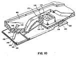
- FIG. 10 is a perspective view of the integrated acoustic position sensing apparatus broken away to reveal the various acoustic transducers therein.
- the film speed sensor comprises a row of eight cylindrical holes 168 defining sensing ports 130 on one side of the body 166 and transducer ports 170 on the opposite side of the body 166.
- the stacked, folded polymeric piezoelectric material is fixed, for example by adhesive, to the surface of the body portion 166 over the transducer ports 170 so that the transmitter electrode 156 and the receiver electrodes 164 (not shown in FIG. 10) are aligned with the transducer ports.
- the film notch sensor comprises a cylindrical hole 172 through a side wall'of lens block 124.
- the opening into the film receiving chamber defines sensing port 128, and the opening 174 on the other side of body 166 defines the transducer port.
- Electrodes 154 and 162 are fixed over transducer port 174.
- the audible signal transducer defined by electrode 160 is fixed over a dome-shaped piece of foam plastic 176 that is inset into a cylindrical depression in body portion 166.
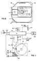
- FIG. 11 An overall schematic diagram of the camera control electronics including the integrated acoustic transducers is shown in FIG. 11.
- the camera is controlled by a microcomputer 178 programmed in a conventional manner for controlling the operation of the camera.
- the microcomputer receives input signals from a conventional light measuring circuit 180, a shutter release button 182, the film notch sensor 184, and the film speed sensor 186.
- Shutter release button 182 operates a switch 183 that supplies power to the microcomputer via a battery 200.
- the film notch sensor 184 is driven by an oscillator 188.
- the signal produced by the sensor is amplified by an amplifier 190 and the output of the amplifier is supplied to a Schmidt trigger 192 to produce a logic level indication of the presence or absence of a film notch at the sensing port of the transducer.
- the logic level signal is supplied to the microcomputer 178.
- the acoustic emitter transducer of film speed sensor 186 is powered by an acoustic frequency oscillator 194.
- the eight acoustic receiver transducers are connected respectively to eight amplifiers 196 and the outputs of the amplifiers are supplied respectively to eight Schmidt triggers 198 to develop logic level signals for the microcomputer.
- the microcomputer controls a shutter/aperture actuator 202, a film advance motor 204, and the audible signal generator 206.
- the audible signal generator 206 is supplied by an audible frequency signal from oscillator 208.
- the microcomputer receives power and proceeds to command the light measuring circuit 180 to measure scene light.
- the computer commands the film speed sensor to measure the film speed, then calculates a desired exposure based on the film speed and scene light in a known manner. If the light is too low for a satisfactory exposure, the computer activates the audible signal generator to warn the photographer of a low light situation. If scene light is sufficient for exposure, the computer 178 commands the shutter/aperture acuator 202 to open the shutter for a prescribed period of time.
- the computer then commands the film advance motor 204 to advance film to the next frame.
- the film notch sensor 184 senses the next film notch 210 on the periphery of the film disc 212
- the motor 204 is stopped and the computer waits for the next actuation of shutter release button 182.
- Acoustic position sensing apparatus of the type for sensing the position of an object with respect to a sensing port in an acoustic resonator is useful in many types of equipment requiring position sensing transducers.
- the acoustic transducers for the acoustic position sensing apparatus are simply constructed by forming electrodes on opposite sides of a sheet of poled piezoelectric material.
- the acoustic transducers are advantageous in having improved mass-productivity.
- the acoustic position sensing apparatus has the further advantage of being very compact and readily miniaturized. Mass productivity and compactness is further improved by integrating a plurality of acoustic transducers on a single sheet of piezoelectric material.
- the acoustic position sensing apparatus when used in a photographic camera to sense film features has the additional advantage of not exposing the film, and not damaging delicate film surfaces by mechanical contact.
Landscapes
- Physics & Mathematics (AREA)
- General Physics & Mathematics (AREA)
- Length Measuring Devices Characterised By Use Of Acoustic Means (AREA)
- Piezo-Electric Transducers For Audible Bands (AREA)
- Indication In Cameras, And Counting Of Exposures (AREA)
Abstract
Description
- The invention relates to acoustic position sensing apparatus of the type for sensing the position of an object with respect to a sensing port in an acoustic resonator.
- Position sensors for producing an electronic signal representing the position of an object are essential parts of many complex electromechanical devices.
- One type of position sensor shown in U.S. Patent No. 3,694,800 issued September 26, 1972 to L. F. Frank, employs the physical principle that the resonant frequency of an acoustic resonator having a port changes as a function of the obstruction of the port. The position sensing apparatus includes a "Y" shaped tube for defining an acoustic resonator. A first acoustic transducer (e.g. a loud speaker) is connected to one branch of the "Y" shaped tube for generating an acoustic signal of predetermined frequency in the acoustic resonator. The stem of the "Y" shaped tube is open, to define a sensing port. The resonant frequency of the acoustic resonator varies as a function of the position of an object near the sensing port. A second acoustic transducer (e.g. a microphone) is connected to the other branch of the "Y" shaped tube, and produces a signal representing the resonant condition in the acoustic resonator. Depending upon the size of the resonator, the size of the sensing port, and the- frequency of the first acoustic transducer, the signal produced by the second acoustic transducer will be a maximum when the sensing port is completely unobstructed (open tube resonance), or completely covered (closed tube resonance). Signal processing electronics responsive to the signal produced by the second acoustic transducer produces a signal representative of the position of an object with respect to the sensing port. In the acoustic position sensing apparatus shown in the aforementioned U.S. patent, the acoustic transducers comprise acoustic transducers of the type used in hearing aids.
- A problem encountered in employing such prior art acoustic position sensors in small, mass-produced apparatus such as photographic cameras is the difficulty in mass-producing the acoustic transducers and incorporating the transducers in small areas, due to their physical size and complexity.
- This problem becomes particularly acute when one attempts to employ a number of acoustic position sensors in one apparatus.
- The object of the invention is to provide acoustic position sensing apparatus that is simply constructed, that has improved mass-productivity, and is easily miniaturized for employment in compact, mass-produced apparatus. A further object of the invention is to provide an acoustic film position sensor for a photographic camera. A still further object is to provide an acoustic film cartridge feature sensor for a photographic camera.
- The objects are achieved by providing acoustic position sensing apparatus having acoustic transducers comprising a sheet of suitably poled piezoelectric material (preferably polymeric material such as polyvinylidene fluoride) having electrodes on opposite sides thereof. The sheet is fixed over a transducer port(s) in an acoustic resonator. To further improve mass-productivity, a plurality of acoustic transducers are integrated on a single sheet of piezoelectric material by patterning the electrodes thereon.
- In one embodiment of the acoustic position sensing apparatus the acoustic resonator comprises a body of material having a pair of spaced- apart cylindrical holes through the thickness of the material. The holes converge near one side of the body to define a V-shaped cavity. The vertex of the V opens onto one surface of the body to form a sensing port. The legs of the V open on an opposite surface of the body to form transducer ports. The acoustic transducers are formed side- by-side on the sheet of polymeric piezoelectric material, such that when the sheet is fixed to the surface of the body having the transducer ports, one acoustic transducer is positioned over each transducer port.
- In another embodiment of the acoustic position sensing apparatus the acoustic resonator is defined by a cylindrical hole through the thickness of a body of material. One end of the hole defines the sensing port, and both acoustic transducers are fixed over the other end of the cylindrical hole, one on top of the other.
- In one application the acoustic position sensing apparatus is employed in a photographic camera, and the acoustic transducers for: (1) an acoustic film notch sensor; (2) a plurality of cartridge notch sensors; and (3) an audio signal emitter are integrated on a single sheet of polymeric piezoelectric material. In addition to the advantages of being compact and easily mass-produced, the use of the acoustic position sensing apparatus in a photographic camera has the advantage that the acoustic signal used to sense film features, or camera part position does not expose film, or damage sensitive film surfaces by mechanical contact.
- The invention will be described with reference to the accompanying drawings, wherein:
- FIG. 1 is a perspective cross-sectional view of acoustic position sensing apparatus for detecting film perforations;
- FIG. 2 is a plan view of a sheet of piezoelectric material employed in the acoustic position sensing apparatus shown in FIG. 1;
- FIG. 3 is a perspective cross-sectional view of an alternative embodiment of acoustic position sensing apparatus for detecting perforations in film;
- FIG. 4 is a plan view showing the electrode structure on a sheet of piezoelectric material. employed in the apparatus of FIG. 3;
- FIG. 5 is a perspective partial cross-sectional view of a further alternative embodiment of acoustic position sensing apparatus;
- FIG. 6 is a plan view showing the electrode structure on a sheet of piezoelectric material employed in the apparatus of FIG. 5;
- FIG. 7 is a plan view of the film-receiving chamber of a disc film camera having a plurality of acoustic position sensing apparatus;
- FIG. 8 is a plan view of a disc film cartridge useful in describing the operation of an acoustic film speed notch sensor included in the camera shown in FIG. 7;
- FIG. 9 is a plan view showing the electrode structure on a sheet of piezoelectric material comprising integrated acoustic transducers used in the camera shown in FIG. 7;
- FIG. 10 is a perspective partial cross-sectional view of the acoustic position sensing apparatus shown in FIG. 7; and
- FIG. 11 is an overall schematic diagram of the control circuit for the acoustic position sensing apparatus shown in FIG. 10.
- WAYS OF CARRYING OUT THE INVENTION Acoustic position sensing apparatus is shown in FIG. 1. The acoustic position sensing apparatus, generally designated 10, is configured for detecting
perforations 12 in a strip offilm 14. The apparatus comprises a body of material 16 (e.g. plastic or metal) defining afilm guide slot 18 and anacoustic resonator 20. The acoustic resonator is defined by a pair of cylindrical holes which converge to meet at a vertex to define a V-shaped cavity, with asensing port 22 at the vertex of the V, opening into the film guide slot, and a pair oftransducer ports V. A sheet 28 of poled piezoelectric material, preferably a polymeric piezoelectric material such as polyvinylidene fluoride (PVF2) comprises the acoustic transducers of the acoustic position sensing apparatus. The acoustic transducers are fixed over thetransducer ports - To further improve mass-productivity, both of the acoustic transducers are formed on a single sheet of piezoelectric material. FIG. 2 shows a plan view of the sheet of
piezoelectric material 28. Two regions of the sheet of material are electrically addressable by means of a pair of patternedelectrodes sheet 28 beneath the patterned electrodes are rendered piezoelectrically active (poled) by applying a high voltage to the electrodes for a predetermined time at a predetermined temperature as is well known in the art. Alternatively, the entire sheet is poled prior to forming the patterned electrodes. The sheet ofpiezoelectric material 28 is fixed over thetransducer ports acoustic resonator 20 so that the regions of the sheet covered by the patterned electrodes are positioned over the ports. Acorner 34 of the sheet is folded over and fixed with adhesive as shown in FIG. 1, to allow contact to be made to the backside electrode. Aconductive cover 36 is placed over the transducers. A pair ofcoaxial connectors cover 36. The cover itself, the ground leads of the coaxial connectors, and the backside electrode ofsheet 28 are grounded, thereby providing electromagnetic interference shielding for the acoustic transducers.Electrode 30 is connected to anacoustic frequency generator 42 throughconnector 38.Electrode 32 is connected to anamplifier 44 throughconnector 40. Directlyopposite sensing port 22 is aback cavity 46, formed by a cylindrical hole covered on one end by a piece oftape 48. - In operation, an acoustic signal is applied by
oscillator 42 toelectrode 30 thereby causing the piezoelectrically active region underelectrode 30 to vibrate overtransducer port 24 to generate an acoustic signal in theacoustic resonator 20. The acoustic signal inacoustic resonator 20 is sensed by the piezoelectrically active region ofsheet 28 fixed overtransducer port 26 thereby generating an electrical signal proportional to the strength of the acoustic signal inacoustic resonator 20, onelectrode 32. The signal onelectrode 32 is amplified byamplifier 44. When the frequency of the acoustic signal in theacoustic resonator 20 is at the resonant frequency of the resonator, the sensed signal will be a maximum. The resonant frequency of the acoustic resonator is a function of the extent to whichsensing port 22 is covered or uncovered. The frequency of the acoustic signal is chosen to coincide with the resonant frequency of the acoustic resonator when the sensing port is covered. Alternatively, the frequency of the acoustic signal is chosen to coincide with the resonant frequency of the acoustic resonator when the sensing port is uncovered. The output ofamplifier 44 is a function of the position of afilm perforation 12 with respect to sensingport 22. - The acoustic position sensing apparatus described above was constructed by drilling a pair of 1 mm diameter holes at 45° angles to define a V-shaped cavity in an 8.5 mm thick sheet of plexi-glass. The polymeric piezoelectric sheet, was 25 um thick, biaxially stretched, PVF2 with .1 pm thick aluminum electrodes vapor deposited through a mask. The diameters of the
top electrodes oscillator 42 until a maximum signal was detected onelectrode 32. A 14.7 kHz, 10 volt square wave was applied toelectrode 30 byoscillator 42. When a film perforation was present at thesensing port 22, the input to theamplifier 44 was .09 mV. When no perforation was present, i.e. with film over thesensing port 22, the input to theamplifier 44 was 1.96 mV. - When back
cavity 46 was opened by removing the piece oftape 48, a resonance was observed at 26.75 kHz with no film present at the sensingPort 22. Under these conditions, when a 26.75 kHz 10 volt square wave was applied toelectrode 30, the input to theamplifier 44 was .23 mV. When film was present between sensingport 22 andback cavity 46, the input to theamplifier 44 was 1.32 mV. - With this small, simple and easily mass-produced apparatus, film perforations are accurately and reliably sensed. Besides being used as a perforation sensor, acoustic position sensing apparatus may also be used as an edge detector, a distance sensor, or a non-contact thickness guage. The thickness gauge is achieved by placing an acoustic position sensor on both sides of a sheet of material and observing the difference in the signals from the two sensors. If the output of
amplifier 44 is applied to a trigger circuit such as a Schmidt trigger, the output of the apparatus becomes a logical binary signal, suitable for use for example as a noncontact switch to indicate the presence or absence of an object covering the sensing port. - FIG. 3 shows an alternative embodiment of acoustic position sensing apparatus where elements analogous to elements in FIG. 1 are similarly numbered, with primes ('). In the apparatus 10' shown in FIG. 3 the regions of the sheet of piezoelectric material 28' covered by patterned electrodes, comprising the acoustic transducers, are stacked over a single transducer port 24' in the acoustic resonator 20', thereby further simplifying the construction of the device and reducing its size. FIG. 4 shows the electrode pattern on one side of the sheet 28' of piezoelectric material. The other side of the sheet is fully covered by an electrode. The sheet 28' is divided, as shown by
phantom lines leaves hole 64 having substantially the same diameter as transducer port 24' is formed inleaf 56. An electrode 32' is formed onleaf 58; an electrode 30' is formed onleaf 60. Electrode 30' includes aconductor leg 30a' that extends ontoleaf 58 fromleaf 60. - When assembled,
leaf 56 is folded back and down (as seen in FIG. 4) alongline 50 so thathole 64 is substantially aligned with the center of electrode 32'. Next,leaf 60 is folded back and up alongline 52 so that electrodes 30' and 32' are in substantial alignment. In the folded stack, electrode 32',conductor leg 30a', and the backside electrode onflap 62 are all accessible from the same side of the stack. In assembling th~ stacked transducer, adhesive is used to hold the contacting surfaces together.Leaf 56 withhole 64 forms an air gap between the two transducer regions of the sheet, thereby improving the acoustic coupling between these regions. The apparatus has been found to work without this spacer, but operation is improved by its presence. - The stacked transducer assembly is then fixed over the single transducer port 24', as shown in FIG. 3, such that electrode 30' is on the bottom in contact with the top surface of block 16'. Electrode 32', a portion of the backside electrode, and
conductor extension 30a' of electrode 30' are exposed for making electrical connections. Electrode 30' is connected to the acoustic frequency generator 42' viacoaxial connector 38'. The backside electrode is connected to ground through the grounded side ofcoaxial connector 38', and electrode 32' is connected to amplifier 44' through coaxial connector 40'. - An acoustic position sensor having a stacked acoustic transducer configuration as shown in FIG. 3, was constructed using 25 p thick biaxially stretched polyvinylidene fluoride sheet with 3 mm diameter evaporated aluminum electrodes. The acoustic resonator was constructed by drilling a 1 mm diameter hole perpendicularly through the thickness of an 8.5 mm thick piece of plexiglass. When a sine wave generator was connected to the bottom electrode 30', open tube resonances were observed at 7.57 kHz and 19.7 kHz, and a closed tube resonance was observed at 12.5 kHz.
- A 23 volt sine wave input having a frequency of 7.57 kHz was applied to the bottom electrode, and the observed input to the sensing amplifier 44' was 1.8 mV with no film present (i.e. at a perforation), and .9 mV amplifier input was observed with film present at the sensing port 22'. With a 12.5 kHz sine wave input, the amplifier input observed was .9 mV with no film present, and 1.9 mV with film present. At 19.7 kHz, the amplifier input was 2.1 mV with no film present, and 1.1 mV with film present. The approximately 2:1 on/off ratios observed with the device make object position detection accurate and reliable.
- FIG. 5 shows a further alternative embodiment of the acoustic position sensing apparatus having a stacked, folded acoustic transducer structure, further simplified by integrating an electromagnetic interference shield into the folded sheet structure. Elements of the device shown in FIG. 5 analogous to the previously described devices are similarly numbered with double primes (").
- FIG. 6 illustrates the electrode pattern on the sheet of
piezoelectric material 28". The sheet is divided byphantom fold lines 50", 52", and 54" into fourleaves 56", 58", 60", and 62".Leaf 56" is provided with acentral aperture 64" substantially the same size astransducer port 24" inacoustic resonator 20" (see FIG. 5).Leaf 58" carries anelectrode 30" having aconductor extension 30a" that extends slightly acrossfold line 52" ontoleaf 60". Similarly,leaf 60" carries anelectrode 32" having a conductor extension 32a" that extends slightly acrossfold line 52" ontoleaf 58".Leaf 62" is substantially narrower thanleaves 58" and 60" and is provided with atab 66, the purpose of which is explained below. The backside ofsheet 28" is covered by one substantially unpatterned electrode. - During assembly,
leaf 56" is folded back and to the right, as seen in FIG. 6, so thathole 64" is in substantial alignment with the center ofelectrode 30".Leaf 58" is then folded back and to the right alongfold line 52" so that theelectrodes 30" and 32" are in substantial alignment, withhole 64" in between them. Next,leaf 62" is folded forward and to the left alongline 54". Finally,tab 66 is folded around the edge atfold line 52". When the unpatterned backside electrode is grounded, the electrode onleaf 62" provides the shielding from electromagnetic interference forelectrode 32". After assembly,conductor extensions 30a" and 32a" are electrically accessible by a flat cable connector 68 (see FIG. 5) alongfold line 52".Tab 66 is folded overfold line 52" as shown in FIG. 5, to provide electrical access to the unpatterned backside electrode.Connector 68 is provided with spring loadedcontacts 70 in a known manner to make electrical contact with theextensions 30a" and 32a" of the patterned electrodes, and the unpatterned backside electrode. -
Electrode 30" is connected via one conductor in a flat, multiple-conductor cable 72 toacoustic generator 42".Electrode 32" is connected viacable 72 toamplifier 44". - To illustrate the use of the acoustic position sensing apparatus shown in FIG. 5 in a binary (onoff) mode, a
Schmidt trigger 71 is shown connected to the output ofamplifier 44". The trigger levels of theSchmidt trigger 71 are set to be between the respective outputs of amplifier, 44" when sensingport 22" is fully covered, and when it is fully uncovered. The arrangement shown in FIG. 5 is particularly well adapted for use as a touch-sensitive switch, for example. - Mass-productivity of the acoustic position sensor is further improved by integrating a number of acoustic transducers on a single sheet of polymeric piezoelectric material. For example, a rectangular or linear array of touch-sensitive switches employing the type of acoustic position sensor shown in FIG. 5 is made by appropriately repeating the electrode patterns shown in FIG. 6 and providing a body of material defining a number of acoustic resonators.
- FIG. 7 illustrates the acoustic position sensing apparatus employed in a photographic camera of the type adapted to expose disc film.
- A camera, generally designated 100 has a hinged film loading door 102 (partially shown in FIG. 7) that swings open to reveal a
chamber 104 for receiving a disc film cartridge. A plan view of a disc film cartridge is shown in FIG. 8. Thefilm cartridge 106 includes aprotective housing 108 having an exposure window (not shown) located on the opposite side of the housing from apressure pad area 110. Afilm drive hub 112 having a keyedaperture 114 is accessible from outside the cartridge for rotating a film disc inside the cartridge to bring successive exposure areas on the film disc into the exposure window. Avane 116 extending fromprotective housing 108 serves as a film speed indicator. Thevane 116 is selectively truncated during manufacture of the film cartridge at any one of eight locations indicated byphantom lines 118 to code for eight possible film speeds ranging fromISO 40 to ISO 1000. Returning now to FIG. 7, the film chamber in the camera includes afilm drive spindle 120, acartridge opening lever 122, and alens block 124 adapted to project into the exposure window of the film cartridge to define the film plane of the camera. When thefilm loading door 102 is swung closed over thechamber 104, acamera latch lever 126 swings in a counterclockwise arc in the direction of arrow A to latch the door closed. Thecamera latch lever 126 is connected tocartridge opening lever 122 and moves the cartridge opening lever to uncover the exposure window in the cartridge after the film loading door is closed. Thelens block 124 extends into the exposure window to contact the film disc in the cartridge. - Film frames around the periphery of the film disc are successively located in the exposure window of the film cartridge by rotating the
film drive spindle 120 in engagement with thefilm drive hub 112. The film disc is provided with a series of peripheral notches that indicate the locations of the respective film frames on the disc. - Film notches, such as the film frame location notches, are sensed by an acoustic film notch sensor having acoustic transducers according to the present invention. A
sensing port 128 for the acoustic film notch sensor is provided inlens block 124. The filmspeed indicator vane 116 onfilm cartridge 106 is also sensed by an acoustic position sensor having acoustic transducers according to the present invention. Eight sensingports 130 are provided for sensingfilm speed vane 116. - The disc camera shown in FIG. 7 is also provided with an audible signal for alerting the photographer to a photographic condition such as a light level too low for picture taking. The audible signal transducer comprises a polymeric piezoelectric transducer located inside the camera body in the
region 132 outlined in phantom in FIG. 7. The plurality of acoustic transducers in the camera are integrated in asingle sheet 134 of piezoelectric material. FIG. 9 is a plan view of the electrode pattern on one side of thesheet 134 of piezoelectric material. The other side of the sheet is covered by a substantially unpatterned electrode. When assembled, the sheet is folded alongfold lines leaves Leaf 142 functions as a spacer and defines anaperture 150 for the film notch sensor and eightapertures 152 for the film speed sensor.Leaf 144 carries apatterned electrode 154 for the acoustic emitter of the film notch sensor and apatterned electrode 156 for the acoustic emitters of the film speed sensor. -
Leaf 146 defines anextension 158 having a patternedelectrode 160 for the audible acoustic signal transducer.Leaf 146 also carries apatterned electrode 162 for the acoustic sensor of the film notch sensor and eight patternedelectrodes 164 for acoustic sensors of the film speed sensor. -
Leaf 148, when folded over the receiver transducers onleaf 146, provides shielding from electromagnetic interference.Leaf 148 has anextension tab 165 for providing electrical contact to the backside electrode as described below. The electrical conductors to the patterned electrodes are grouped in one area of thesheet 134, alongfold line 138 for convenient connection to an external circuit by a flat connector of the type shown above in FIG. 5. - To assemble the transducer,
leaf 142 is folded back and to the right, as seen in FIG. 9, so that theapertures electrodes leaf 144. Next,leaf 146 is folded back and to the left alongline 138, so thatelectrodes electrodes leaf 144, withapertures leaf 148 is folded alongline 140 to coverelectrodes tab 165 is folded overedge 138. The surfaces of thesheet 134 that contact each other are fixed with adhesive in the manner described above. The folded and stacked assembly is then fixed to the back of a portion of the camera defining the cartridge receiving chamber. - FIG. 10 is a perspective view of the integrated acoustic position sensing apparatus broken away to reveal the various acoustic transducers therein. A portion of the
camera body 166 formed, for example by injection molded plastic, defines the acoustic resonators for the acoustic measurement apparatus. - The film speed sensor comprises a row of eight
cylindrical holes 168 definingsensing ports 130 on one side of thebody 166 andtransducer ports 170 on the opposite side of thebody 166. The stacked, folded polymeric piezoelectric material is fixed, for example by adhesive, to the surface of thebody portion 166 over thetransducer ports 170 so that thetransmitter electrode 156 and the receiver electrodes 164 (not shown in FIG. 10) are aligned with the transducer ports. - The film notch sensor comprises a
cylindrical hole 172 through a sidewall'of lens block 124. The opening into the film receiving chamber defines sensingport 128, and theopening 174 on the other side ofbody 166 defines the transducer port.Electrodes 154 and 162 (not shown in FIG. 10) are fixed overtransducer port 174. - The audible signal transducer defined by
electrode 160 is fixed over a dome-shaped piece offoam plastic 176 that is inset into a cylindrical depression inbody portion 166. - An overall schematic diagram of the camera control electronics including the integrated acoustic transducers is shown in FIG. 11. The camera is controlled by a
microcomputer 178 programmed in a conventional manner for controlling the operation of the camera. The microcomputer receives input signals from a conventionallight measuring circuit 180, ashutter release button 182, thefilm notch sensor 184, and thefilm speed sensor 186.Shutter release button 182 operates aswitch 183 that supplies power to the microcomputer via abattery 200. - The
film notch sensor 184 is driven by anoscillator 188. The signal produced by the sensor is amplified by anamplifier 190 and the output of the amplifier is supplied to a Schmidt trigger 192 to produce a logic level indication of the presence or absence of a film notch at the sensing port of the transducer. The logic level signal is supplied to themicrocomputer 178. The acoustic emitter transducer offilm speed sensor 186 is powered by anacoustic frequency oscillator 194. The eight acoustic receiver transducers are connected respectively to eightamplifiers 196 and the outputs of the amplifiers are supplied respectively to eight Schmidt triggers 198 to develop logic level signals for the microcomputer. - In response to the signals received by the input transducers, the microcomputer controls a shutter/
aperture actuator 202, afilm advance motor 204, and theaudible signal generator 206. Theaudible signal generator 206 is supplied by an audible frequency signal fromoscillator 208. - When
shutter release button 182 is depressed, the microcomputer receives power and proceeds to command thelight measuring circuit 180 to measure scene light. The computer commands the film speed sensor to measure the film speed, then calculates a desired exposure based on the film speed and scene light in a known manner. If the light is too low for a satisfactory exposure, the computer activates the audible signal generator to warn the photographer of a low light situation. If scene light is sufficient for exposure, thecomputer 178 commands the shutter/aperture acuator 202 to open the shutter for a prescribed period of time. The computer then commands thefilm advance motor 204 to advance film to the next frame. When thefilm notch sensor 184 senses thenext film notch 210 on the periphery of thefilm disc 212, themotor 204 is stopped and the computer waits for the next actuation ofshutter release button 182. - Acoustic position sensing apparatus of the type for sensing the position of an object with respect to a sensing port in an acoustic resonator is useful in many types of equipment requiring position sensing transducers. The acoustic transducers for the acoustic position sensing apparatus are simply constructed by forming electrodes on opposite sides of a sheet of poled piezoelectric material. The acoustic transducers are advantageous in having improved mass-productivity. The acoustic position sensing apparatus has the further advantage of being very compact and readily miniaturized. Mass productivity and compactness is further improved by integrating a plurality of acoustic transducers on a single sheet of piezoelectric material. The acoustic position sensing apparatus, when used in a photographic camera to sense film features has the additional advantage of not exposing the film, and not damaging delicate film surfaces by mechanical contact.
Claims (8)
Applications Claiming Priority (2)
| Application Number | Priority Date | Filing Date | Title |
|---|---|---|---|
| US06/531,375 US4494841A (en) | 1983-09-12 | 1983-09-12 | Acoustic transducers for acoustic position sensing apparatus |
| US531375 | 2000-03-21 |
Publications (2)
| Publication Number | Publication Date |
|---|---|
| EP0155270A1 EP0155270A1 (en) | 1985-09-25 |
| EP0155270B1 true EP0155270B1 (en) | 1988-08-24 |
Family
ID=24117370
Family Applications (1)
| Application Number | Title | Priority Date | Filing Date |
|---|---|---|---|
| EP84901508A Expired EP0155270B1 (en) | 1983-09-12 | 1984-03-16 | Acoustic position sensing apparatus |
Country Status (5)
| Country | Link |
|---|---|
| US (1) | US4494841A (en) |
| EP (1) | EP0155270B1 (en) |
| JP (1) | JPS60502017A (en) |
| DE (1) | DE3473644D1 (en) |
| WO (1) | WO1985001343A1 (en) |
Families Citing this family (14)
| Publication number | Priority date | Publication date | Assignee | Title |
|---|---|---|---|---|
| US4711808A (en) * | 1986-02-19 | 1987-12-08 | Eastman Kodak Company | Beta phase PVF2 film formed by casting it onto a specially prepared insulating support |
| DK163451C (en) * | 1987-08-05 | 1992-07-20 | Eskofot As | METHOD FOR DETECTING ISAER THIN FILMS |
| US4850232A (en) * | 1988-04-15 | 1989-07-25 | Eastman Kodak Company | System for measuring the dimensions of a workpiece |
| US5161126A (en) * | 1991-05-29 | 1992-11-03 | Eastman Kodak Company | Acoustic flute web edge sensor |
| US5138586A (en) * | 1991-05-29 | 1992-08-11 | Eastman Kodak Company | Acoustic logic circuits |
| US5410608A (en) * | 1992-09-29 | 1995-04-25 | Unex Corporation | Microphone |
| DE4446367A1 (en) * | 1994-12-23 | 1996-06-27 | Giesecke & Devrient Gmbh | Method and device for the dynamic determination of the thickness and / or the basis weight of moving measured material |
| US6025725A (en) * | 1996-12-05 | 2000-02-15 | Massachusetts Institute Of Technology | Electrically active resonant structures for wireless monitoring and control |
| US6749573B2 (en) * | 2000-02-14 | 2004-06-15 | The United States Of America As Represented By The Administrator Of The National Aeronautics And Space Administration | Passive fetal heart monitoring system |
| RU2196354C1 (en) * | 2001-10-18 | 2003-01-10 | Государственное унитарное предприятие Научно-исследовательский кинофотоинститут | Method controlling position of motion-picture or photographic film |
| US20060116602A1 (en) * | 2004-12-01 | 2006-06-01 | Alden Dana A | Medical sensing device and system |
| US8288922B2 (en) * | 2006-06-30 | 2012-10-16 | The Penn State Research Foundation | Flexoelectric—piezoelectric composite based on flexoelectric charge separation |
| US8979021B2 (en) * | 2011-10-17 | 2015-03-17 | Easton Corporation | Hydraulic air bleed valve system |
| US8833695B2 (en) * | 2011-10-17 | 2014-09-16 | Eaton Corporation | Aircraft hydraulic air bleed valve system |
Citations (1)
| Publication number | Priority date | Publication date | Assignee | Title |
|---|---|---|---|---|
| US3802406A (en) * | 1971-12-28 | 1974-04-09 | Sibe | Fuel feed devices for internal combustion engines |
Family Cites Families (11)
| Publication number | Priority date | Publication date | Assignee | Title |
|---|---|---|---|---|
| US3694800A (en) * | 1970-04-24 | 1972-09-26 | Eastman Kodak Co | Acoustical gauge |
| US3702406A (en) * | 1970-11-09 | 1972-11-07 | Eastman Kodak Co | Fluid operated control apparatus responsive to sensing a plurality of members containing one of two codes |
| US3914754A (en) * | 1971-05-18 | 1975-10-21 | Martonair Ltd | Machine element position detection system |
| US3798959A (en) * | 1972-08-11 | 1974-03-26 | Bowles Fluidics Corp | Acoustic gauge and fluidic signal processing circuitry therefor |
| BE840456A (en) * | 1975-04-22 | 1976-10-07 | DEVICE FOR PRECISE MEASUREMENT OF THE DIMENSIONS OF AN OBJECT BY ULTRA-SOUND | |
| US4309089A (en) * | 1977-12-20 | 1982-01-05 | Eastman Kodak Company | Exposure indicating apparatus responsive to film exposure latitude |
| US4175441A (en) * | 1978-05-08 | 1979-11-27 | Tencor Instruments | Gauge for measuring distance to planar surfaces and thicknesses of planar members |
| US4383194A (en) * | 1979-05-01 | 1983-05-10 | Toray Industries, Inc. | Electro-acoustic transducer element |
| US4285053A (en) * | 1979-05-21 | 1981-08-18 | Tencor Instruments | Acoustic method and apparatus for measuring micron and submicron distances |
| NL7904924A (en) * | 1979-06-25 | 1980-12-30 | Philips Nv | ACOUSTIC TRANSDUCER. |
| FR2519503B1 (en) * | 1981-12-31 | 1991-09-06 | Thomson Csf | POLYMERIC PIEZOELECTRIC TRANSDUCERS AND MANUFACTURING METHOD |
-
1983
- 1983-09-12 US US06/531,375 patent/US4494841A/en not_active Expired - Fee Related
-
1984
- 1984-03-16 DE DE8484901508T patent/DE3473644D1/en not_active Expired
- 1984-03-16 JP JP59501539A patent/JPS60502017A/en active Granted
- 1984-03-16 WO PCT/US1984/000394 patent/WO1985001343A1/en not_active Ceased
- 1984-03-16 EP EP84901508A patent/EP0155270B1/en not_active Expired
Patent Citations (1)
| Publication number | Priority date | Publication date | Assignee | Title |
|---|---|---|---|---|
| US3802406A (en) * | 1971-12-28 | 1974-04-09 | Sibe | Fuel feed devices for internal combustion engines |
Also Published As
| Publication number | Publication date |
|---|---|
| US4494841A (en) | 1985-01-22 |
| DE3473644D1 (en) | 1988-09-29 |
| JPS60502017A (en) | 1985-11-21 |
| JPH0341762B2 (en) | 1991-06-25 |
| EP0155270A1 (en) | 1985-09-25 |
| WO1985001343A1 (en) | 1985-03-28 |
Similar Documents
| Publication | Publication Date | Title |
|---|---|---|
| US4494841A (en) | Acoustic transducers for acoustic position sensing apparatus | |
| Sessler | Acoustic sensors | |
| US4678905A (en) | Optical sensors for detecting physical parameters utilizing vibrating piezoelectric elements | |
| US5029215A (en) | Automatic calibrating apparatus and method for second-order gradient microphone | |
| JP2007243999A (en) | Electroacoustic transducer | |
| JPH0929169A (en) | Vibration transmitting plate, manufacturing method thereof, and coordinate input device | |
| JPH06508498A (en) | Mechanical vibration canceling piezoceramic microphone | |
| US5282388A (en) | Air flow measuring apparatus | |
| US5161126A (en) | Acoustic flute web edge sensor | |
| WO1992020048A1 (en) | Audio information exchange | |
| EP3964808B1 (en) | Detection sensor and detection device including the same | |
| GB2064263A (en) | Microphone unit | |
| US3925668A (en) | Spectral sensor and method | |
| JPH0711447B2 (en) | Acceleration sensor | |
| EP4521080A1 (en) | Detection sensor | |
| JPS623827Y2 (en) | ||
| US4134649A (en) | Sound motion picture camera | |
| JP2770488B2 (en) | Semiconductor pressure gauge | |
| US4285021A (en) | Circuit for generating an audible signal in tape recorders at the tape end | |
| US4351114A (en) | Process for measuring using standard blocks and a standard measuring block | |
| JPS5913674Y2 (en) | Buzzer volume adjustment device | |
| JPS5830633B2 (en) | Vibration detector for security alarm | |
| KR20210148788A (en) | Bluetooth earphone with non-contact temperature measurement | |
| JPS59224526A (en) | Fine oscillation detector | |
| JPS61254825A (en) | pyroelectric sensor |
Legal Events
| Date | Code | Title | Description |
|---|---|---|---|
| PUAI | Public reference made under article 153(3) epc to a published international application that has entered the european phase |
Free format text: ORIGINAL CODE: 0009012 |
|
| 17P | Request for examination filed |
Effective date: 19850418 |
|
| AK | Designated contracting states |
Designated state(s): DE FR GB |
|
| 17Q | First examination report despatched |
Effective date: 19870210 |
|
| GRAA | (expected) grant |
Free format text: ORIGINAL CODE: 0009210 |
|
| AK | Designated contracting states |
Kind code of ref document: B1 Designated state(s): DE FR GB |
|
| REF | Corresponds to: |
Ref document number: 3473644 Country of ref document: DE Date of ref document: 19880929 |
|
| ET | Fr: translation filed | ||
| PLBE | No opposition filed within time limit |
Free format text: ORIGINAL CODE: 0009261 |
|
| STAA | Information on the status of an ep patent application or granted ep patent |
Free format text: STATUS: NO OPPOSITION FILED WITHIN TIME LIMIT |
|
| 26N | No opposition filed | ||
| PGFP | Annual fee paid to national office [announced via postgrant information from national office to epo] |
Ref country code: GB Payment date: 19920228 Year of fee payment: 9 |
|
| PGFP | Annual fee paid to national office [announced via postgrant information from national office to epo] |
Ref country code: FR Payment date: 19920320 Year of fee payment: 9 |
|
| PGFP | Annual fee paid to national office [announced via postgrant information from national office to epo] |
Ref country code: DE Payment date: 19920326 Year of fee payment: 9 |
|
| PG25 | Lapsed in a contracting state [announced via postgrant information from national office to epo] |
Ref country code: GB Effective date: 19930316 |
|
| GBPC | Gb: european patent ceased through non-payment of renewal fee |
Effective date: 19930316 |
|
| PG25 | Lapsed in a contracting state [announced via postgrant information from national office to epo] |
Ref country code: FR Effective date: 19931130 |
|
| PG25 | Lapsed in a contracting state [announced via postgrant information from national office to epo] |
Ref country code: DE Effective date: 19931201 |
|
| REG | Reference to a national code |
Ref country code: FR Ref legal event code: ST |