EP0155253B1 - Anti-skid device - Google Patents
Anti-skid device Download PDFInfo
- Publication number
- EP0155253B1 EP0155253B1 EP85850091A EP85850091A EP0155253B1 EP 0155253 B1 EP0155253 B1 EP 0155253B1 EP 85850091 A EP85850091 A EP 85850091A EP 85850091 A EP85850091 A EP 85850091A EP 0155253 B1 EP0155253 B1 EP 0155253B1
- Authority
- EP
- European Patent Office
- Prior art keywords
- arms
- disc
- wheel
- friction
- ground
- Prior art date
- Legal status (The legal status is an assumption and is not a legal conclusion. Google has not performed a legal analysis and makes no representation as to the accuracy of the status listed.)
- Expired
Links
- 239000002184 metal Substances 0.000 claims 1
- 230000007704 transition Effects 0.000 abstract 1
- 230000004224 protection Effects 0.000 description 8
- 230000033001 locomotion Effects 0.000 description 7
- 238000013016 damping Methods 0.000 description 4
- 239000000725 suspension Substances 0.000 description 2
- 230000006978 adaptation Effects 0.000 description 1
- 230000005540 biological transmission Effects 0.000 description 1
- 238000010276 construction Methods 0.000 description 1
- 230000008094 contradictory effect Effects 0.000 description 1
- 230000008878 coupling Effects 0.000 description 1
- 238000010168 coupling process Methods 0.000 description 1
- 238000005859 coupling reaction Methods 0.000 description 1
- 239000000463 material Substances 0.000 description 1
- 238000000034 method Methods 0.000 description 1
- 239000004033 plastic Substances 0.000 description 1
- 230000002787 reinforcement Effects 0.000 description 1
- 238000005096 rolling process Methods 0.000 description 1
Images
Classifications
-
- B—PERFORMING OPERATIONS; TRANSPORTING
- B60—VEHICLES IN GENERAL
- B60B—VEHICLE WHEELS; CASTORS; AXLES FOR WHEELS OR CASTORS; INCREASING WHEEL ADHESION
- B60B39/00—Increasing wheel adhesion
- B60B39/003—Vehicle mounted non-skid chains actuated by centrifugal force
-
- Y—GENERAL TAGGING OF NEW TECHNOLOGICAL DEVELOPMENTS; GENERAL TAGGING OF CROSS-SECTIONAL TECHNOLOGIES SPANNING OVER SEVERAL SECTIONS OF THE IPC; TECHNICAL SUBJECTS COVERED BY FORMER USPC CROSS-REFERENCE ART COLLECTIONS [XRACs] AND DIGESTS
- Y10—TECHNICAL SUBJECTS COVERED BY FORMER USPC
- Y10T—TECHNICAL SUBJECTS COVERED BY FORMER US CLASSIFICATION
- Y10T152/00—Resilient tires and wheels
- Y10T152/10—Tires, resilient
- Y10T152/10279—Cushion
Definitions
- This invention relates to a device for increasing the friction or grip between vehicle wheels and ground, especially for private cars, of the kind comprising a rotable, substantially disc-shaped means with arms or spokes intended to be successively continuously fed in between wheel and ground in use.
- a device for increasing the friction or grip between vehicle wheels and ground especially for private cars, of the kind comprising a rotable, substantially disc-shaped means with arms or spokes intended to be successively continuously fed in between wheel and ground in use.
- This is a so-called automatic anti-skid devices but “automatic” does not mean that the anti-skid devices are activated automatically when the roads get slippery, but instead they can be activated by the driver during a ride.
- An anti-skid device of this type is known from US-A-27 47 691 incorporating fork-like radial arms of reinforced rubber. The are further provided with friction increasing means.
- the known device cannot be used thus from a stationary car without a preceding wheel spin which is directly dangerous in traffic at private cars as a consequence of higher power/weight conditions.
- a device for private cars must give a low increase of the sound level and be useful at high speeds.
- a further problem with private cars is the need of a skid protection also at the front wheels. Whether these are driving or only guiding. Of course it is a desideratum that the skid protection should not only be fully efficient at movements straight ahead but also when the car is on lock. Lock means however, that very great differences in radius will occur between the position where the wheel starts to roll over the skid protection and where this is again released, respectively. Moreover, it must be considered that some modern cars have a geometry being such that the contact surface between wheel and ground is moved laterally as well as longitudinally relative to the car at steering movements.
- the arms or spokes made solely of unreinforced rubber allowing a stretching of 50-100% in a radial direction and also giving a lateral flexibility. In this way the spokes are also able to cope with the angle between the spoke and the friction increasing outer end lying beneath the wheel. This angle changes when the car is moving.
- the arms are elastic all the way to the centre of rotation of the disc or close to this.
- stiffness or damping means are arranged at the spokes which limit the freedom of movement within certain limits. This is possible as in the first place a very great elasticity is necessary in radial direction and, secondly, it is important that the spokes or the arms in the neighbourhood of the friction increasing member may be angled in the plane of the disc. In this way it is possible to arrange the stiffening members in the form of means only damping and guiding, respectively, the movement of the spokes perpendicularly to the plane of the disc.
- each spoke may be enclosed in an elastic tubular element, e.g. in the form of a helical spring.
- the arms are hollow and take up in their internal cavity a stiffening or damping element which can ensure the necessary stiffening.
- the disc should be rotated by the arms being held between wheel and ground while the car is moving forwards, as distinguished from the so far known, single, functioning devices provided with chains where a special element is used to speed up the chain pulley so that the chains are thrown in between wheel and ground.
- the stiffening means abut on wheel and/or ground to define the position relative to the wheel as well as achieve an extra drive of the device.
- the elastic arms or spokes are preferably made of rubber and a rubber or plastic material can also be used for the stiffening means, possibly in the form of a disc. However, as the stiffening means need not allow of a great radial elongation these can be reinforced and in this way easily be given the stability of form required.
- the disc-shaped element provided with arms or spokes is preferably relatively plane with the spokes perpendicular to the axis of rotation.
- the arms are preferably arranged considerably tighter than what is the case when using chains. As the disc is plane in position of rest it is easy to give this a place under the car. As the disc is rotated by the arms being gripped successively no certain minimum speed is required for function but the device can start to operate from a stationary position.
- the number of arms and the distance between these at the periphery are less than half the length of the contact surface of the vehicle wheel so that at least two arms are constantly between wheel and ground.
- the arms or spokes in the part coming into contact between wheel and ground can be provided with friction increasing members of the type studs or the like and it can also be suitable to form the arms with such a width in this section that there is no risk of upset, rotation or turning.
- These studs can either be disposed straight through the friction increasing members or more or less diagonally in these in view of the fact that the force transmission at drive as well as braking will take place in a diagonal direction.
- the arms are elastic and can be extended and bent in use the risk of disturbance as a consequence of deposits in the form of ice, snow or the like, which can be obtained at long drives with the friction element in parking position, will be eliminated.
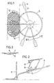
- FIG. 1 shows the inventive device as seen from above
- Fig. 2 is a front view of the device
- Fig. 3 is a section taken on the line III-III in Fig. 1.
- the friction increasing device consists in the first place of arms attached in the vicinity of the bearing 1, which are flexible vertically and laterally and elastic longitudinally.
- the outer ends 3 of the arms are wider to prevent the arms from rotating or rolling under the vehicle wheel.
- the arms are provided with studs 4 in the outer ends.
- the arms are made of rubber and without reinforcement at least in the part extending from the attachment to the friction increasing outer end 3. As a consequence of this and the angle length of the arm this can be stretched very strongly in radial direction. The fact is that it allows of stretching of 50-100%.
- a disc 5 is arranged above those which is arranged as rotating together with the arms above the latter.
- an elastic ring 6 which lies under the arms. The ring 6 is attached to the disc 5 between the arms (at 7).
- the disc 5, the ring 6 and the points of attachment 7 do not only serve to stiffen up the device to a disc-like element but will also function to damp motion of the arms 2. Otherwise the arms will easily perform so great pivotations in radial; tangential or normal direction, when they come out from their held-fast position between wheel and ground, that it would disturb their repeated throw under the wheel. However, these movements will have time to be damped during the rotation of the arm until the next throw-in.
- the overhead disc 5 will abut on the side of the wheel and is then bent.
- the disc-like traction device is attached via the bearing 1 to a parallelogram mounting 8 which is actuated, when the device is activated, by an outwardly directed force 10 until the parallelogram 8 will abut on a stop 9.
- the device 8 is either attached to a part of the wheel suspension of the car or at a suitable place of the car body. As a consequence of the great elasticity of the device it is possible for it to adapt itself to the spring and steering movement of the vehicle at the same time as a good function is continuously guaranteed.
- the anti-skid device is rotated when the friction increasing arms or spokes are successively drawn in between ground and wheel it is necessary with a tangential coupling between the arms. As mentioned above, this can be achieved by means of the stiffening members. However, it is very well possible within the scope of the invention that this function is accomplished by a lateral connection between the arms, e.g. immediately inside the friction increasing flat portion. These lateral connections can be more or less elastic and either free of the stiffening members or, as an alternative, cooperating with these. It is even possible that the damping and stiffening members do not influence directly on the arms but via these members connecting the arms laterally.
- the arms are framework constructions and then, in particular, in vertical direction.
- the framework can consist of a triangle. In this way a vertical stiffening can be achieved.
Landscapes
- Engineering & Computer Science (AREA)
- Mechanical Engineering (AREA)
- Vibration Dampers (AREA)
- Braking Arrangements (AREA)
- Arrangement Or Mounting Of Propulsion Units For Vehicles (AREA)
Abstract
Description
- This invention relates to a device for increasing the friction or grip between vehicle wheels and ground, especially for private cars, of the kind comprising a rotable, substantially disc-shaped means with arms or spokes intended to be successively continuously fed in between wheel and ground in use. This is a so-called automatic anti-skid devices but "automatic" does not mean that the anti-skid devices are activated automatically when the roads get slippery, but instead they can be activated by the driver during a ride.
- An anti-skid device of this type is known from US-A-27 47 691 incorporating fork-like radial arms of reinforced rubber. The are further provided with friction increasing means.
- This type of anti-skid device has however shown itself incapable of dealing with the great forces that are exerted. Instead the so far successfully marketed single "automatic" anti-skid device employ short chain pieces arranged on a pulley and thrown in under a vehicle wheel by the rotation of the pulley when this is forced to contact with said wheel. However, the use of anti-skid protections of this type has only been possible with trucks as the space is enough there to allow of application of the entire equipment required inclusive of the position of rest of the pulley provided with chains. Moreover, only trucks are so expensive that they can stand the additional costs of these automatic anti-skid protections. However, the need for an automatic anti-skid protection operated from the driving compartment is great in private cars, also, especially against the background that many countries do not permit studded tyres. In the Alpine countries of Europe this often means that snow chains must repeatedly be taken on and off. It should also be mentioned in this connection that a careful adjustment of the working position of the chain pulley relative to the vehicle wheel is necessary for a good function of the known devices. At cars with front wheel drive in particular, as well as cars with independent rear suspension this makes the use of chain pulleys impossible. Moreover, very great forces necessarily appear in use. A further drawback of known technique is the fact that the chains must be thrown in under the vehicle wheel by the rotation of the pulley. Then the chains excert a braking force on the rotation of the pulley, which thus skids against the side of the vehicle wheel. This is less desirable at private cars than at trucks as the tyres are more delicate. Furthermore, the known device cannot be used thus from a stationary car without a preceding wheel spin which is directly dangerous in traffic at private cars as a consequence of higher power/weight conditions. In view of the above problems it is the object of the invention to provide an automatic anti-skid device which is so compact that it can be used with private cars, with an uncritical position relative to the vehicle wheel, and which can start its function also at a slow start of the car from a standstill position. Moreover, a device for private cars must give a low increase of the sound level and be useful at high speeds.
- A further problem with private cars is the need of a skid protection also at the front wheels. Whether these are driving or only guiding. Of course it is a desideratum that the skid protection should not only be fully efficient at movements straight ahead but also when the car is on lock. Lock means however, that very great differences in radius will occur between the position where the wheel starts to roll over the skid protection and where this is again released, respectively. Moreover, it must be considered that some modern cars have a geometry being such that the contact surface between wheel and ground is moved laterally as well as longitudinally relative to the car at steering movements.
- Thus, it is required from an adequate skid protection that it must be extremely flexible and, moreover, must have a sufficient stiffness or stability to ensure a correct adaptation. These requirements are quite contradictory to each other and have so far resulted in that nobody has even tried to achieve automatic skid protections for private cars and, in particular, their front wheels.
- The above problems are solved in accordance with the invention in that, in the first place the apparently incompatible claims on flexibility and stiffness are completely disregarded and priority is exclusively given to the flexibility. Thus are according to the invention the arms or spokes made solely of unreinforced rubber allowing a stretching of 50-100% in a radial direction and also giving a lateral flexibility. In this way the spokes are also able to cope with the angle between the spoke and the friction increasing outer end lying beneath the wheel. This angle changes when the car is moving.
- In order to obtain, in particular, a great radial elasticity it is suitable that the arms are elastic all the way to the centre of rotation of the disc or close to this.
- In order to meet in a further development of the inventive thought the demands on sufficient stiffness and guiding of the spokes when these are to be positioned under the wheel with their ends and in connection with parking of the device, stiffness or damping means are arranged at the spokes which limit the freedom of movement within certain limits. This is possible as in the first place a very great elasticity is necessary in radial direction and, secondly, it is important that the spokes or the arms in the neighbourhood of the friction increasing member may be angled in the plane of the disc. In this way it is possible to arrange the stiffening members in the form of means only damping and guiding, respectively, the movement of the spokes perpendicularly to the plane of the disc. This can be carried out in a relatively simple way using preferably a light, elastic disc or several discs arranged above or below the spokes or arms. Alternatively, each spoke may be enclosed in an elastic tubular element, e.g. in the form of a helical spring. In analogy with this it is of course also possible that the arms are hollow and take up in their internal cavity a stiffening or damping element which can ensure the necessary stiffening.
- It is intended at the inventive object, in the first place, that the disc should be rotated by the arms being held between wheel and ground while the car is moving forwards, as distinguished from the so far known, single, functioning devices provided with chains where a special element is used to speed up the chain pulley so that the chains are thrown in between wheel and ground. However, it is quite possible within the scope of the invention to have the stiffening means abut on wheel and/or ground to define the position relative to the wheel as well as achieve an extra drive of the device.
- The elastic arms or spokes are preferably made of rubber and a rubber or plastic material can also be used for the stiffening means, possibly in the form of a disc. However, as the stiffening means need not allow of a great radial elongation these can be reinforced and in this way easily be given the stability of form required. The disc-shaped element provided with arms or spokes is preferably relatively plane with the spokes perpendicular to the axis of rotation. The arms are preferably arranged considerably tighter than what is the case when using chains. As the disc is plane in position of rest it is easy to give this a place under the car. As the disc is rotated by the arms being gripped successively no certain minimum speed is required for function but the device can start to operate from a stationary position. The number of arms and the distance between these at the periphery are less than half the length of the contact surface of the vehicle wheel so that at least two arms are constantly between wheel and ground.
- In order to improve the increase of friction the arms or spokes in the part coming into contact between wheel and ground can be provided with friction increasing members of the type studs or the like and it can also be suitable to form the arms with such a width in this section that there is no risk of upset, rotation or turning. These studs can either be disposed straight through the friction increasing members or more or less diagonally in these in view of the fact that the force transmission at drive as well as braking will take place in a diagonal direction. As the arms are elastic and can be extended and bent in use the risk of disturbance as a consequence of deposits in the form of ice, snow or the like, which can be obtained at long drives with the friction element in parking position, will be eliminated.
- As a consequence of the great elasticity of the friction increasing arms no great stresses arise on the bearing of the disc and its attachment, and therefore the support can be given moderate dimensions and, accordingly, weight and space.
- Further advantages and properties of the invention will appear from the description below of an illustrative example shown on the drawings. Fig. 1 shows the inventive device as seen from above, Fig. 2 is a front view of the device and Fig. 3 is a section taken on the line III-III in Fig. 1.
- The friction increasing device consists in the first place of arms attached in the vicinity of the bearing 1, which are flexible vertically and laterally and elastic longitudinally. The
outer ends 3 of the arms are wider to prevent the arms from rotating or rolling under the vehicle wheel. Besides, the arms are provided with studs 4 in the outer ends. The arms are made of rubber and without reinforcement at least in the part extending from the attachment to the friction increasingouter end 3. As a consequence of this and the angle length of the arm this can be stretched very strongly in radial direction. The fact is that it allows of stretching of 50-100%. - As is evident, the angular position between the friction increasing
outer end 3 and the part of the arm which is substantially radial all the time from the throw-inposition 12 to the extendedposition 14, changes. It is very easy for the elastic arm to adapt itself also to this. - In order to collect the extremely
elastic arms 2 to a disc-shaped element adisc 5 is arranged above those which is arranged as rotating together with the arms above the latter. At the periphery of the disc there is an elastic ring 6 which lies under the arms. The ring 6 is attached to thedisc 5 between the arms (at 7). - The
disc 5, the ring 6 and the points ofattachment 7 do not only serve to stiffen up the device to a disc-like element but will also function to damp motion of thearms 2. Otherwise the arms will easily perform so great pivotations in radial; tangential or normal direction, when they come out from their held-fast position between wheel and ground, that it would disturb their repeated throw under the wheel. However, these movements will have time to be damped during the rotation of the arm until the next throw-in. - In the case shown the
overhead disc 5 will abut on the side of the wheel and is then bent. The disc-like traction device is attached via the bearing 1 to a parallelogram mounting 8 which is actuated, when the device is activated, by an outwardly directedforce 10 until the parallelogram 8 will abut on astop 9. The device 8 is either attached to a part of the wheel suspension of the car or at a suitable place of the car body. As a consequence of the great elasticity of the device it is possible for it to adapt itself to the spring and steering movement of the vehicle at the same time as a good function is continuously guaranteed. - Since the anti-skid device is rotated when the friction increasing arms or spokes are successively drawn in between ground and wheel it is necessary with a tangential coupling between the arms. As mentioned above, this can be achieved by means of the stiffening members. However, it is very well possible within the scope of the invention that this function is accomplished by a lateral connection between the arms, e.g. immediately inside the friction increasing flat portion. These lateral connections can be more or less elastic and either free of the stiffening members or, as an alternative, cooperating with these. It is even possible that the damping and stiffening members do not influence directly on the arms but via these members connecting the arms laterally.
- Within the scope of the invention it is imaginable that the arms are framework constructions and then, in particular, in vertical direction. In the simplest case the framework can consist of a triangle. In this way a vertical stiffening can be achieved.
Claims (8)
Priority Applications (1)
| Application Number | Priority Date | Filing Date | Title |
|---|---|---|---|
| AT85850091T ATE46868T1 (en) | 1984-03-15 | 1985-03-13 | ANTI-SLIP DEVICE. |
Applications Claiming Priority (2)
| Application Number | Priority Date | Filing Date | Title |
|---|---|---|---|
| SE8401456A SE8401456D0 (en) | 1984-03-15 | 1984-03-15 | SLIDE PROTECTION, SPECIFICALLY FOR CAR |
| SE8401456 | 1984-03-15 |
Publications (3)
| Publication Number | Publication Date |
|---|---|
| EP0155253A2 EP0155253A2 (en) | 1985-09-18 |
| EP0155253A3 EP0155253A3 (en) | 1985-11-27 |
| EP0155253B1 true EP0155253B1 (en) | 1989-10-04 |
Family
ID=20355164
Family Applications (1)
| Application Number | Title | Priority Date | Filing Date |
|---|---|---|---|
| EP85850091A Expired EP0155253B1 (en) | 1984-03-15 | 1985-03-13 | Anti-skid device |
Country Status (6)
| Country | Link |
|---|---|
| US (1) | US4732239A (en) |
| EP (1) | EP0155253B1 (en) |
| AT (1) | ATE46868T1 (en) |
| CA (1) | CA1259646A (en) |
| DE (1) | DE3573395D1 (en) |
| SE (1) | SE8401456D0 (en) |
Families Citing this family (2)
| Publication number | Priority date | Publication date | Assignee | Title |
|---|---|---|---|---|
| JP2545543B2 (en) * | 1987-06-26 | 1996-10-23 | 雅生 犬塚 | Wheel trampling device |
| SE459961C (en) * | 1988-02-09 | 1991-01-14 | Goeran Toernebaeck | SLIP PROTECTION DEVICE |
Family Cites Families (10)
| Publication number | Priority date | Publication date | Assignee | Title |
|---|---|---|---|---|
| US1403270A (en) * | 1918-10-03 | 1922-01-10 | David P Small | Antiskid device |
| US2747691A (en) * | 1952-11-05 | 1956-05-29 | Frank J Lakey | Retractable traction and antiskid device for vehicles |
| US2865471A (en) * | 1956-12-26 | 1958-12-23 | Francis P Chaussee | Anti-skid device for vehicles |
| US2886138A (en) * | 1957-07-01 | 1959-05-12 | Abrom D Bruner | Automatic traction device for vehicles |
| DE1162216B (en) * | 1958-10-28 | 1964-01-30 | Hanns Schnitzler Dipl Ing | Anti-skid device for vehicles with rubber tires, especially motor vehicles |
| FR2036889A1 (en) * | 1969-04-15 | 1970-12-31 | Bonnet Jean | |
| DE2610048A1 (en) * | 1976-03-11 | 1977-09-15 | Josef Koller | Remote control snow grips for tyre - with freely rotating grips on retractable hub to run under wheels |
| CH642006A5 (en) * | 1978-04-10 | 1984-03-30 | Goeran Toernebaeck | SLIDING PROTECTION DEVICE FOR VEHICLE WHEELS ON A MOTOR VEHICLE. |
| SE8400204D0 (en) * | 1984-01-17 | 1984-01-17 | Tornebecks Verksteder Kb | DEVICE FOR AUTOMATIC SNOW CHAIN |
| SE8402335D0 (en) * | 1984-04-27 | 1984-04-27 | Tornebecks Verksteder Kb | SLIP PROTECTION DEVICE |
-
1984
- 1984-03-15 SE SE8401456A patent/SE8401456D0/en unknown
-
1985
- 1985-03-13 EP EP85850091A patent/EP0155253B1/en not_active Expired
- 1985-03-13 AT AT85850091T patent/ATE46868T1/en not_active IP Right Cessation
- 1985-03-13 DE DE8585850091T patent/DE3573395D1/en not_active Expired
- 1985-03-14 CA CA000476494A patent/CA1259646A/en not_active Expired
-
1986
- 1986-10-29 US US06/925,492 patent/US4732239A/en not_active Expired - Fee Related
Also Published As
| Publication number | Publication date |
|---|---|
| EP0155253A2 (en) | 1985-09-18 |
| DE3573395D1 (en) | 1989-11-09 |
| ATE46868T1 (en) | 1989-10-15 |
| SE8401456D0 (en) | 1984-03-15 |
| CA1259646A (en) | 1989-09-19 |
| EP0155253A3 (en) | 1985-11-27 |
| US4732239A (en) | 1988-03-22 |
Similar Documents
| Publication | Publication Date | Title |
|---|---|---|
| CA1138314A (en) | Anti-skid device for motor vehicles | |
| US4520890A (en) | Brake arrangement for snowmobile | |
| US2241923A (en) | Automatic emergency traction device for automobiles | |
| SE463409B (en) | DRIVING BOGGI FOR LARV VEHICLE | |
| CA1259647A (en) | Anti-skid device | |
| US4732239A (en) | Anti-skid device | |
| EP0370106B1 (en) | Treading device for wheels | |
| RU2159193C1 (en) | Device to improve cross-country capacity of automobile | |
| US2865471A (en) | Anti-skid device for vehicles | |
| US5735980A (en) | Traction device for a wheeled vehicle | |
| US2767809A (en) | Anti-skid device for automobiles | |
| US4176704A (en) | Emergency traction device | |
| EP0151098B1 (en) | Antiskid device with remote control | |
| WO1984004071A1 (en) | Anti-skid device for vehicles | |
| US4852948A (en) | Traction device | |
| US2195982A (en) | Antiskid device | |
| US3965956A (en) | Bumper mounted spring driven tire installer and remover | |
| US4643251A (en) | Traction devices for automotive wheels | |
| JPH0235027Y2 (en) | ||
| US2780315A (en) | Anti-skid apparatus for vehicles | |
| US3428151A (en) | Traction device for automotive vehicles | |
| CN2208512Y (en) | Skid-proof device for vehicles | |
| FR2543094A1 (en) | ROAD VEHICLE COMPRISING A AXLE WITH GUIDELINES | |
| SU1444233A1 (en) | Light single-track cross-country vehicle | |
| KR100566922B1 (en) | Anti slip for tire mounting |
Legal Events
| Date | Code | Title | Description |
|---|---|---|---|
| PUAI | Public reference made under article 153(3) epc to a published international application that has entered the european phase |
Free format text: ORIGINAL CODE: 0009012 |
|
| AK | Designated contracting states |
Designated state(s): AT BE CH DE FR GB IT LI LU NL SE |
|
| PUAL | Search report despatched |
Free format text: ORIGINAL CODE: 0009013 |
|
| AK | Designated contracting states |
Designated state(s): AT BE CH DE FR GB IT LI LU NL SE |
|
| 17P | Request for examination filed |
Effective date: 19860520 |
|
| 17Q | First examination report despatched |
Effective date: 19870424 |
|
| GRAA | (expected) grant |
Free format text: ORIGINAL CODE: 0009210 |
|
| AK | Designated contracting states |
Kind code of ref document: B1 Designated state(s): AT BE CH DE FR GB IT LI LU NL SE |
|
| PG25 | Lapsed in a contracting state [announced via postgrant information from national office to epo] |
Ref country code: NL Effective date: 19891004 Ref country code: BE Effective date: 19891004 |
|
| REF | Corresponds to: |
Ref document number: 46868 Country of ref document: AT Date of ref document: 19891015 Kind code of ref document: T |
|
| REF | Corresponds to: |
Ref document number: 3573395 Country of ref document: DE Date of ref document: 19891109 |
|
| ITF | It: translation for a ep patent filed | ||
| ET | Fr: translation filed | ||
| PG25 | Lapsed in a contracting state [announced via postgrant information from national office to epo] |
Ref country code: GB Effective date: 19900313 |
|
| NLV1 | Nl: lapsed or annulled due to failure to fulfill the requirements of art. 29p and 29m of the patents act | ||
| PG25 | Lapsed in a contracting state [announced via postgrant information from national office to epo] |
Ref country code: LU Free format text: LAPSE BECAUSE OF NON-PAYMENT OF DUE FEES Effective date: 19900331 |
|
| PLBE | No opposition filed within time limit |
Free format text: ORIGINAL CODE: 0009261 |
|
| STAA | Information on the status of an ep patent application or granted ep patent |
Free format text: STATUS: NO OPPOSITION FILED WITHIN TIME LIMIT |
|
| 26N | No opposition filed | ||
| GBPC | Gb: european patent ceased through non-payment of renewal fee | ||
| PGFP | Annual fee paid to national office [announced via postgrant information from national office to epo] |
Ref country code: CH Payment date: 19920326 Year of fee payment: 8 |
|
| ITTA | It: last paid annual fee | ||
| PGFP | Annual fee paid to national office [announced via postgrant information from national office to epo] |
Ref country code: AT Payment date: 19920331 Year of fee payment: 8 |
|
| PGFP | Annual fee paid to national office [announced via postgrant information from national office to epo] |
Ref country code: SE Payment date: 19930210 Year of fee payment: 9 |
|
| PG25 | Lapsed in a contracting state [announced via postgrant information from national office to epo] |
Ref country code: AT Effective date: 19930313 |
|
| PGFP | Annual fee paid to national office [announced via postgrant information from national office to epo] |
Ref country code: FR Payment date: 19930317 Year of fee payment: 9 |
|
| PG25 | Lapsed in a contracting state [announced via postgrant information from national office to epo] |
Ref country code: LI Effective date: 19930331 Ref country code: CH Effective date: 19930331 |
|
| PGFP | Annual fee paid to national office [announced via postgrant information from national office to epo] |
Ref country code: DE Payment date: 19930528 Year of fee payment: 9 |
|
| REG | Reference to a national code |
Ref country code: CH Ref legal event code: PL |
|
| PG25 | Lapsed in a contracting state [announced via postgrant information from national office to epo] |
Ref country code: SE Free format text: LAPSE BECAUSE OF NON-PAYMENT OF DUE FEES Effective date: 19940314 |
|
| PG25 | Lapsed in a contracting state [announced via postgrant information from national office to epo] |
Ref country code: FR Effective date: 19941130 |
|
| PG25 | Lapsed in a contracting state [announced via postgrant information from national office to epo] |
Ref country code: DE Effective date: 19941201 |
|
| REG | Reference to a national code |
Ref country code: FR Ref legal event code: ST |
|
| EUG | Se: european patent has lapsed |
Ref document number: 85850091.1 Effective date: 19941010 |