EP0155209B1 - Elastic support device - Google Patents
Elastic support device Download PDFInfo
- Publication number
- EP0155209B1 EP0155209B1 EP85400312A EP85400312A EP0155209B1 EP 0155209 B1 EP0155209 B1 EP 0155209B1 EP 85400312 A EP85400312 A EP 85400312A EP 85400312 A EP85400312 A EP 85400312A EP 0155209 B1 EP0155209 B1 EP 0155209B1
- Authority
- EP
- European Patent Office
- Prior art keywords
- ring
- bore
- elastomer
- stop
- central
- Prior art date
- Legal status (The legal status is an assumption and is not a legal conclusion. Google has not performed a legal analysis and makes no representation as to the accuracy of the status listed.)
- Expired
Links
Images

Classifications
-
- F—MECHANICAL ENGINEERING; LIGHTING; HEATING; WEAPONS; BLASTING
- F16—ENGINEERING ELEMENTS AND UNITS; GENERAL MEASURES FOR PRODUCING AND MAINTAINING EFFECTIVE FUNCTIONING OF MACHINES OR INSTALLATIONS; THERMAL INSULATION IN GENERAL
- F16F—SPRINGS; SHOCK-ABSORBERS; MEANS FOR DAMPING VIBRATION
- F16F3/00—Spring units consisting of several springs, e.g. for obtaining a desired spring characteristic
- F16F3/08—Spring units consisting of several springs, e.g. for obtaining a desired spring characteristic with springs made of a material having high internal friction, e.g. rubber
- F16F3/10—Spring units consisting of several springs, e.g. for obtaining a desired spring characteristic with springs made of a material having high internal friction, e.g. rubber combined with springs made of steel or other material having low internal friction
-
- B—PERFORMING OPERATIONS; TRANSPORTING
- B61—RAILWAYS
- B61F—RAIL VEHICLE SUSPENSIONS, e.g. UNDERFRAMES, BOGIES OR ARRANGEMENTS OF WHEEL AXLES; RAIL VEHICLES FOR USE ON TRACKS OF DIFFERENT WIDTH; PREVENTING DERAILING OF RAIL VEHICLES; WHEEL GUARDS, OBSTRUCTION REMOVERS OR THE LIKE FOR RAIL VEHICLES
- B61F5/00—Constructional details of bogies; Connections between bogies and vehicle underframes; Arrangements or devices for adjusting or allowing self-adjustment of wheel axles or bogies when rounding curves
- B61F5/02—Arrangements permitting limited transverse relative movements between vehicle underframe or bolster and bogie; Connections between underframes and bogies
- B61F5/04—Bolster supports or mountings
- B61F5/08—Bolster supports or mountings incorporating rubber springs
-
- B—PERFORMING OPERATIONS; TRANSPORTING
- B61—RAILWAYS
- B61F—RAIL VEHICLE SUSPENSIONS, e.g. UNDERFRAMES, BOGIES OR ARRANGEMENTS OF WHEEL AXLES; RAIL VEHICLES FOR USE ON TRACKS OF DIFFERENT WIDTH; PREVENTING DERAILING OF RAIL VEHICLES; WHEEL GUARDS, OBSTRUCTION REMOVERS OR THE LIKE FOR RAIL VEHICLES
- B61F5/00—Constructional details of bogies; Connections between bogies and vehicle underframes; Arrangements or devices for adjusting or allowing self-adjustment of wheel axles or bogies when rounding curves
- B61F5/02—Arrangements permitting limited transverse relative movements between vehicle underframe or bolster and bogie; Connections between underframes and bogies
- B61F5/04—Bolster supports or mountings
- B61F5/10—Bolster supports or mountings incorporating fluid springs
-
- B—PERFORMING OPERATIONS; TRANSPORTING
- B61—RAILWAYS
- B61F—RAIL VEHICLE SUSPENSIONS, e.g. UNDERFRAMES, BOGIES OR ARRANGEMENTS OF WHEEL AXLES; RAIL VEHICLES FOR USE ON TRACKS OF DIFFERENT WIDTH; PREVENTING DERAILING OF RAIL VEHICLES; WHEEL GUARDS, OBSTRUCTION REMOVERS OR THE LIKE FOR RAIL VEHICLES
- B61F5/00—Constructional details of bogies; Connections between bogies and vehicle underframes; Arrangements or devices for adjusting or allowing self-adjustment of wheel axles or bogies when rounding curves
- B61F5/02—Arrangements permitting limited transverse relative movements between vehicle underframe or bolster and bogie; Connections between underframes and bogies
- B61F5/04—Bolster supports or mountings
- B61F5/12—Bolster supports or mountings incorporating dampers
- B61F5/125—Bolster supports or mountings incorporating dampers with rubber elements
-
- F—MECHANICAL ENGINEERING; LIGHTING; HEATING; WEAPONS; BLASTING
- F16—ENGINEERING ELEMENTS AND UNITS; GENERAL MEASURES FOR PRODUCING AND MAINTAINING EFFECTIVE FUNCTIONING OF MACHINES OR INSTALLATIONS; THERMAL INSULATION IN GENERAL
- F16F—SPRINGS; SHOCK-ABSORBERS; MEANS FOR DAMPING VIBRATION
- F16F1/00—Springs
- F16F1/36—Springs made of rubber or other material having high internal friction, e.g. thermoplastic elastomers
- F16F1/3615—Springs made of rubber or other material having high internal friction, e.g. thermoplastic elastomers with means for modifying the spring characteristic
Definitions
- the present invention relates to an elastic support device comprising an elastic elastomer ring in which are disposed rigid intermediate rings which adhere to the elastomer, the elastic ring thus having a laminated structure in the axial direction, and being able to particular be mounted in series with a coil spring, in particular in a secondary suspension of railway bogie.
- Document FR-A-2354229 has proposed a resilient support device for a secondary suspension of a railway bogie comprising two elastomer springs with rigid intermediate rings, a frustoconical spring and a hollow cylindrical spring, fixed to the external frame of the frustoconical spring, which can penetrate under load inside the annular cylindrical spring.
- Such a device is somewhat complex and does not make it possible to obtain gradually increasing horizontal deflection stiffness as a function of the radial force, for a given axial load.
- the object of the present invention is to provide an elastic support device ensuring low horizontal deflection rigidity for low radial forces, then increasingly higher when the radial force increases.
- the device according to the invention is characterized in that it comprises, at the center of the bore of the elastomer ring, a coaxial central stop, the external surface of which is separated, in the absence of stress from the ring, of the elastomer surface of the bore of the ring and is likely to come into progressive contact with said elastomer surface of the bore, which deforms when the ring is subjected to increasing stress in one direction radial.
- the outer surface of the central stop is made of elastomer.
- the outer surface of the central stop has a generally frustoconical shape, the bore of the ring having a generally cylindrical shape.
- the external surface of the stop is shaped so as to form with the bore of the ring an annular space whose radial section increases from the base of the stop towards its other end.
- the central stop is formed by an elastomer cushion adhered to the outside of a mandrel.
- the outer elastomer surface of the stopper and the surface of the bore of the ring form waves of revolution around the axis of the ring.
- the intermediate rings located at the height of the central stop each have a bore whose diameter is greater than the diameter of the bore of the ring so that said bore is embedded in the mass of elastomer.
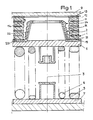
- the device comprises an elastic ring 1 made of elastomer having a laminated or sandwich structure. It is mounted in series with helical springs 4, 5. The load is supported by a support plate 9 on the ring 1.
- the elastomer ring 1 and the helical springs are centered on a same vertical axis 3 along which an axial compression load is exerted.
- the ring 1 is supported on the springs 4 and 5 by means of an upper support cup 6.
- the helical springs are supported on a lower support cup 7.
- the elastomer ring 1 has terminal straight sections which are adhered to two rigid frames 13 and 15.
- the upper frame 13 is integral with the support plate 9 for example of a railway body.
- the lower frame 15 is centered so as to be immobilized horizontally on the upper cup 6.
- the ring comprises intermediate metal rings 11 which extend horizontally at different heights in the thickness of the elastomer. These intermediate rings 11 are preferably arranged at substantially equal intervals between the end reinforcements and they are adhered to the elastomer 12.
- the surface 14 of the bore of the ring is made of elastomer and has a generally cylindrical shape.
- the device has, at the center of the bore of the ring 1, a central stop 2 whose outer surface 24 is separated by a non-zero and finite distance from the surface 14 of the bore of the ring 1.
- the distance measured horizontally increases from bottom to top so that the maximum deflection is on the upper side.
- the central stop 2 is formed by an elastomer cushion 21 adhered to the external surface of a central metal mandrel 22.
- This mandrel has a central part of revolution (cylindrical or frustoconical) on which the cushion is adhered. This part is integral with an annular collar 221 which is immobilized on the upper support cup 6.
- the lower frame 15 of the ring 1 is centered so as to be immobilized horizontally on top of the collar 221.
- the cushion 21 has the form of a sleeve which envelops the mandrel 22.
- the outer surface 24 of the cushion 21 is shaped so as to form with the cylindrical bore of the ring an annular space whose horizontal section increases from bottom to top.
- Intermediate rings 11 located at the height of the central stop 2 each have a bore whose diameter is greater than the diameter of the bore of the ring so that the bores of the rings considered are embedded in the mass of the elastomer.
- the external surface 24 of the central stop 2 and the surface 14 of the bore of the ring 1 form waves of revolution around the axis 3.
- the height of the central stop 2 is less than the height of the ring 1.
- the elastomer cushion 21 forms a buffer at the upper part of the stop so as to constitute an axial elastic stop.
- annular membrane 81 closes the space between the stop 1 and the ring 2 so as to form a chamber 82.
- This chamber 82 contains a fluid.
- FIG. 3 gives the variation of the horizontal deflection as a function of the horizontal force for the assembly constituted by the helical springs, the ring and the stop (curve 1).
- the ring 1 and the central stop 2 can be molded together or separately.
- the elastomer of the ring could be adhered directly to the upper cup of the spring or to the collar 221.
- the outer surface of the stop could be made of polyamide or another plastic material.
Description
La présente invention se rapporte à un dispositif d'appui élastique comportant un anneau élastique en élastomère dans lequel sont disposés des anneaux intercalaires rigides qui adhèrent à l'élastomère, l'anneau élastique présentant ainsi une structure feuilletée dans le sens axial, et pouvant en particulier être monté en série avec un ressort hélicoïdal, notamment dans une suspension secondaire de bogie ferroviaire.The present invention relates to an elastic support device comprising an elastic elastomer ring in which are disposed rigid intermediate rings which adhere to the elastomer, the elastic ring thus having a laminated structure in the axial direction, and being able to particular be mounted in series with a coil spring, in particular in a secondary suspension of railway bogie.
Il a été proposé dans le document FR-A-2354229 un dispositif d'appui élastique pour suspension secondaire de bogie ferroviaire comprenant deux ressorts en élastomère avec anneaux intercalaires rigides, un ressort tronconique et un ressort cylindrique creux, fixé à l'armature extérieure du ressort tronconique, lequel peut pénétrer en charge à l'intérieur du ressort cylindrique annulaire. Un tel dispositif est un peu complexe et ne permet pas d'obtenir une rigidité à la déflection horizontale progressivement croissante en fonction de l'effort radial, pour une charge axiale donnée.Document FR-A-2354229 has proposed a resilient support device for a secondary suspension of a railway bogie comprising two elastomer springs with rigid intermediate rings, a frustoconical spring and a hollow cylindrical spring, fixed to the external frame of the frustoconical spring, which can penetrate under load inside the annular cylindrical spring. Such a device is somewhat complex and does not make it possible to obtain gradually increasing horizontal deflection stiffness as a function of the radial force, for a given axial load.
La présente invention a pour but de procurer un dispositif d'appui élastique assurant une rigidité à la déflection horizontale faible pour de faibles efforts radiaux, puis de plus en plus élevée quand l'effort radial croît.The object of the present invention is to provide an elastic support device ensuring low horizontal deflection rigidity for low radial forces, then increasingly higher when the radial force increases.
Le dispositif selon l'invention est caractérisé par le fait qu'il comporte, au centre de l'alésage de l'anneau en élastomère, une butée centrale coaxiale, dont la surface extérieure est séparée, en l'absence de sollicitation de l'anneau, de la surface en élastomère de l'alésage de l'anneau et est susceptible d'entrer progressivement en contact avec ladite surface en élastomère de l'alésage, qui se déforme lorsque l'anneau est soumis à une sollicitation croissante dans une direction radiale.The device according to the invention is characterized in that it comprises, at the center of the bore of the elastomer ring, a coaxial central stop, the external surface of which is separated, in the absence of stress from the ring, of the elastomer surface of the bore of the ring and is likely to come into progressive contact with said elastomer surface of the bore, which deforms when the ring is subjected to increasing stress in one direction radial.
Selon une caractéristique, la surface extérieure de la butée centrale est en élastomère.According to one characteristic, the outer surface of the central stop is made of elastomer.
Selon une caractéristique, la surface extérieure de la butée centrale a une forme générale tronconique, l'alésage de l'anneau ayant une forme générale cylindrique.According to one characteristic, the outer surface of the central stop has a generally frustoconical shape, the bore of the ring having a generally cylindrical shape.
Selon une autre caractéristique, la surface extérieure de la butée est conformée de manière à former avec l'alésage de l'anneau un espace annulaire dont la section radiale augmente de la base de la butée vers son autre extrémité.According to another characteristic, the external surface of the stop is shaped so as to form with the bore of the ring an annular space whose radial section increases from the base of the stop towards its other end.
Selon une autre caractéristique, la butée centrale est formée par un coussin en élastomère adhérisé à l'extérieur d'un mandrin.According to another characteristic, the central stop is formed by an elastomer cushion adhered to the outside of a mandrel.
Selon une autre caractéristique, la surface extérieure en élastomère de la butée et la surface de l'alésage de l'anneau forment des ondes de révolution autour de l'axe de l'anneau.According to another characteristic, the outer elastomer surface of the stopper and the surface of the bore of the ring form waves of revolution around the axis of the ring.
Selon une autre caractéristique, les anneaux intercalaires situés à la hauteur de la butée centrale présentent chacun un alésage dont le diamètre est supérieur au diamètre de l'alésage de l'anneau de manière que ledit alésage soit noyé dans la masse d'élastomère.According to another characteristic, the intermediate rings located at the height of the central stop each have a bore whose diameter is greater than the diameter of the bore of the ring so that said bore is embedded in the mass of elastomer.
L'invention va maintenant être décrite avec plus de détails en se référant à des modes de réalisation donnés à titre d'exemples et représentés par les dessins annexés sur lesquels :
- La figure 1 représente une coupe axiale d'un mode de réalisation du dispositif selon l'invention.
- La figure 2 est une variante de la figure 1.
- La figure 3 est un diagramme donnant la déflection horizontale en fonction de l'effort horizontal appliqué au dispositif.
- FIG. 1 represents an axial section of an embodiment of the device according to the invention.
- Figure 2 is a variant of Figure 1.
- FIG. 3 is a diagram giving the horizontal deflection as a function of the horizontal force applied to the device.
En se référant aux figures, le dispositif comporte un anneau élastique 1 en élastomère présentant une structure feuilletée ou sandwich. Il est monté en série avec des ressorts hélicoïdaux 4, 5. La charge s'appuie par l'intermédiaire d'une plaque d'appui 9 sur l'anneau 1. L'anneau en élastomère 1 et les ressorts hélicoïdaux sont centrés sur un même axe vertical 3 selon lequel s'exerce une charge axiale de compression. L'anneau 1 s'appuie sur les ressorts 4 et 5 par l'intermédiaire d'une coupelle d'appui supérieure 6. Les ressorts hélicoïdaux s'appuient sur une coupelle d'appui inférieure 7.Referring to the figures, the device comprises an elastic ring 1 made of elastomer having a laminated or sandwich structure. It is mounted in series with
L'anneau en élastomère 1 présente des sections droites terminales qui sont adhérées à deux armatures rigides 13 et 15. L'armature supérieure 13 est solidaire de la plaque d'appui 9 par exemple d'une caisse ferroviaire. L'armature inférieure 15 est centrée de manière à être immobilisée horizontalement sur la coupelle supérieure 6. L'anneau comporte des anneaux métalliques intercalaires 11 qui s'étendent horizontalement à différentes hauteurs dans l'épaisseur de l'élastomère. Ces anneaux intercalaires 11 sont de préférence disposés à des intervalles sensiblement égaux entre les armatures terminales et ils sont adhérés à l'élastomère 12. La surface 14 de l'alésage de l'anneau est en élastomère et a une forme générale cylindrique.The elastomer ring 1 has terminal straight sections which are adhered to two
Le dispositif présente, au centre de l'alésage de l'anneau 1, une butée centrale 2 dont la surface extérieure 24 est séparée par une distance non nulle et finie de la surface 14 de l'alésage de l'anneau 1. La distance mesurée horizontalement augmente de bas en haut de manière que la déflection maximum soit du côté supérieur.The device has, at the center of the bore of the ring 1, a
La butée centrale 2 est formée par un coussin en élastomère 21 adhérisé à la surface extérieure d'un mandrin métallique central 22. Ce mandrin présente une partie centrale de révolution (cylindrique ou tronconique) sur laquelle est adhérisé le coussin. Cette partie est solidaire d'un collet annulaire 221 qui est immobilisé sur la coupelle d'appui supérieure 6. L'armature inférieure 15 de l'anneau 1 est centrée de manière à être immobilisée horizontalement sur le dessus du collet 221. Le coussin 21 a la forme d'un manchon qui enveloppe le mandrin 22. La surface extérieure 24 du coussin 21 est conformée de manière à former avec l'alésage cylindrique de l'anneau un espace annulaire dont la section horizontale augmente de bas en haut. Les anneaux intercalaires 11 situés à la hauteur de la butée centrale 2 présentent chacun un alésage dont le diamètre est supérieur au diamètre de l'alésage de l'anneau de manière que les alésages des anneaux considérés soient noyés dans la masse de l'élastomère.The
La surface extérieure 24 de la butée centrale 2 et la surface 14 de l'alésage de l'anneau 1 forment des ondes de révolution autour de l'axe 3.The
La hauteur de la butée centrale 2 est inférieure à la hauteur de l'anneau 1. Le coussin en élastomère 21 forme un tampon à la partie supérieure de la butée de manière à constituer une butée élastique axiale.The height of the
Dans le mode de réalisation de la figure 2, une membrane annulaire 81 ferme l'espace entre la butée 1 et l'anneau 2 de manière à former une chambre 82. Cette chambre 82 contient un fluide.In the embodiment of FIG. 2, an
Le fonctionnement du dispositif va maintenant être expliqué.The operation of the device will now be explained.
Sous l'effet d'une sollicitation horizontale, l'anneau 1 se déforme et la surface en élastomère de l'alésage 14 vient progressivement en contact avec la surface en élastomère 24 de la butée. Plus la sollicitation horizontale augmente plus la surface de contact entre 14 et 24 augmente, la déflection étant maximum à la partie supérieure. La figure 3 donne la variation de la déflection horizontale en fonction de l'effort horizontal pour l'ensemble constitué par les ressorts hélicoïdaux, l'anneau et la butée (courbe 1).Under the effect of a horizontal stress, the ring 1 deforms and the elastomer surface of the
Il est bien entendu que l'on peut, sans sortir du cadre de l'invention, imaginer des variantes et des perfectionnements de détail et de même envisager l'emploi de moyens équivalents. L'anneau 1 et la butée centrale 2 peuvent être moulés ensemble ou séparément. L'élastomère de l'anneau pourrait être adhérisé directement sur la coupelle supérieure du ressort ou sur le collet 221. La portée extérieure de la butée pourrait être en polyamide ou en une autre matière plastique.It is understood that one can, without departing from the scope of the invention, imagine variants and improvements in detail and even consider the use of equivalent means. The ring 1 and the
Claims (10)
Applications Claiming Priority (2)
| Application Number | Priority Date | Filing Date | Title |
|---|---|---|---|
| FR8402810 | 1984-02-24 | ||
| FR8402810A FR2560322B1 (en) | 1984-02-24 | 1984-02-24 | ELASTIC SUPPORT DEVICE |
Publications (2)
| Publication Number | Publication Date |
|---|---|
| EP0155209A1 EP0155209A1 (en) | 1985-09-18 |
| EP0155209B1 true EP0155209B1 (en) | 1988-07-27 |
Family
ID=9301352
Family Applications (1)
| Application Number | Title | Priority Date | Filing Date |
|---|---|---|---|
| EP85400312A Expired EP0155209B1 (en) | 1984-02-24 | 1985-02-21 | Elastic support device |
Country Status (5)
| Country | Link |
|---|---|
| US (1) | US4630807A (en) |
| EP (1) | EP0155209B1 (en) |
| CA (1) | CA1240207A (en) |
| DE (1) | DE3564016D1 (en) |
| FR (1) | FR2560322B1 (en) |
Families Citing this family (11)
| Publication number | Priority date | Publication date | Assignee | Title |
|---|---|---|---|---|
| DE3833182A1 (en) * | 1988-09-30 | 1990-04-05 | Freudenberg Carl Fa | RUBBER BEARING |
| DE3840156A1 (en) * | 1988-11-29 | 1990-05-31 | Freudenberg Carl Fa | ELASTIC BEARING FOR A BODY |
| US5287027A (en) * | 1991-11-01 | 1994-02-15 | Fmc Corporation | Electromagnetic drive for use with vibratory conveyors |
| US5183137A (en) * | 1991-12-20 | 1993-02-02 | Lord Corporation | Dual-rate surface effect dampers |
| JP3526117B2 (en) * | 1994-11-07 | 2004-05-10 | 株式会社小松製作所 | Liquid filled suspension |
| GB9924816D0 (en) * | 1999-10-21 | 1999-12-22 | Powell Duffryn Standard Ltd | Primary suspension for a rail vehicle |
| WO2001063142A1 (en) * | 2000-02-23 | 2001-08-30 | Woco Avs Gmbh & Co. Betriebs Kg | Hydraulic bearing |
| FR2806452B1 (en) * | 2000-03-20 | 2002-05-03 | Hutchinson | VIBRATION DAMPER ESPECIALLY FOR A HELICOPTER ROTOR |
| FR2960844B1 (en) | 2010-06-08 | 2012-07-06 | Hutchinson | SOMMIER TILT AND SECONDARY SUSPENSION COMPRISING SAME |
| RU196132U1 (en) * | 2019-08-05 | 2020-02-18 | Акционерное общество "Научно-производственная корпорация "Уралвагонзавод имени Ф.Э.Дзержинского" | Suspension beam with wear-resistant thrust bearing |
| RU193276U1 (en) * | 2019-08-05 | 2019-10-22 | Акционерное общество "Научно-производственная корпорация "Уралвагонзавод" имени Ф.Э. Дзержинского" | Suspension beam with wear-resistant thrust bearing |
Family Cites Families (9)
| Publication number | Priority date | Publication date | Assignee | Title |
|---|---|---|---|---|
| US36498A (en) * | 1862-09-23 | Improvement in air-springs | ||
| FR617246A (en) * | 1925-10-08 | 1927-02-16 | Damper | |
| US2573108A (en) * | 1947-07-03 | 1951-10-30 | Transit Res Corp | Rail truck suspension |
| BE556892A (en) * | 1956-06-25 | |||
| US3118659A (en) * | 1960-02-09 | 1964-01-21 | Luxembourg Brev Participations | Compression springs made of an elastomer |
| GB918661A (en) * | 1960-04-08 | 1963-02-13 | Gen Electric Co Ltd | Improvements in or relating to anti-vibration mountings |
| FR1255804A (en) * | 1960-04-30 | 1961-03-10 | Hansens Gummi & Packungswerke | Elastic suspension for vehicles, in particular for rail vehicles |
| FR2354229A1 (en) * | 1976-06-11 | 1978-01-06 | Kleber Colombes | Secondary suspension between railway vehicle body and bogie frame - has frusto=conical spring below cylindrical spring, with concentric conical layers of rubber |
| FR2363469A1 (en) * | 1976-08-31 | 1978-03-31 | Soule Ets Ind | Rail wagon bogie with filled PTFE bearings - has laminated rubber and metal springs for use on rough or short radius stack systems |
-
1984
- 1984-02-24 FR FR8402810A patent/FR2560322B1/en not_active Expired
-
1985
- 1985-02-14 CA CA000474313A patent/CA1240207A/en not_active Expired
- 1985-02-15 US US06/702,028 patent/US4630807A/en not_active Expired - Fee Related
- 1985-02-21 EP EP85400312A patent/EP0155209B1/en not_active Expired
- 1985-02-21 DE DE8585400312T patent/DE3564016D1/en not_active Expired
Also Published As
| Publication number | Publication date |
|---|---|
| DE3564016D1 (en) | 1988-09-01 |
| FR2560322A1 (en) | 1985-08-30 |
| US4630807A (en) | 1986-12-23 |
| FR2560322B1 (en) | 1986-06-20 |
| EP0155209A1 (en) | 1985-09-18 |
| CA1240207A (en) | 1988-08-09 |
Similar Documents
| Publication | Publication Date | Title |
|---|---|---|
| EP0155209B1 (en) | Elastic support device | |
| EP0126006B1 (en) | Connecting device between a vehicle body and a suspension leg | |
| EP0943062B1 (en) | Vehicle wheel suspensions using spring combined with flexible armouring for modifying the stiffness curve | |
| EP0191703B1 (en) | Hydraulic antivibration mounts | |
| EP1217249B1 (en) | Anti-vibration bush and motor vehicle comprising said bush | |
| EP1301733B1 (en) | Travel limit stop device for a motor vehicle damper, and method for making same | |
| EP0410896A1 (en) | Improvements on hydraulic vibration dampers | |
| FR2812362A1 (en) | HYDRAULIC ANTIVIBRATORY SUPPORT AND MANUFACTURING METHOD THEREOF | |
| EP0667466A1 (en) | Suspension element for mounting between two structural elements, especially between a container and a platform | |
| FR2626947A1 (en) | ELASTIC SLEEVE WITH FLUID FILLING COMPRISING AN ELASTIC BODY PRE-COMPRESSED RADIALLY INWARDS | |
| FR2699123A1 (en) | Vibration damper for motor vehicles. | |
| EP0255434A1 (en) | Hydraulic damping mountings | |
| EP0287455A1 (en) | Hydroelastic mounting, particularly for the suspension of a vehicle engine | |
| EP2282076B1 (en) | Anti-vibration device for a vehicle and vehicle including such a device | |
| EP0511907B1 (en) | Improvements to hydraulic anti-vibration devices | |
| FR2863944A1 (en) | Strut for motor vehicle, has spring up with support for suspension spring of vehicle, where support is extended radially up to axial front surface of stop and is fixed to spring up by interlocking connection | |
| CH577126A5 (en) | Vibration damping isolating mount for engines - are similar are effective in three orthogonal planes and have silicone inside domed cover | |
| FR2820180A1 (en) | Automobile pneumatic suspension spring comprises closed section flexible element connecting lower base to upper end plate to form sealed chamber, piston in base moved to and fro in chamber by force moving it toward plate | |
| FR3034046A1 (en) | STOP SUSPENSION DEVICE | |
| FR2645802A1 (en) | Motor vehicle rear suspension assembly | |
| FR2699245A1 (en) | Helical suspension spring for vehicles with variable flexibility - includes central part having bi-conic configuration which extends from median zone and whose one spiral embeds itself inside larger dia. spiral under heavy load | |
| EP1293701B1 (en) | Antivibration support and antivibration device comprising the same | |
| EP1508722B1 (en) | Fastener with pneumatic spring, especially for a motor vehicle suspension, and a motor vehicle comprising the same | |
| EP3742018B1 (en) | Hydraulic anti-vibration mounting | |
| FR2841603A1 (en) | SUSPENSION DEVICE FOR ELECTRIC PUMP |
Legal Events
| Date | Code | Title | Description |
|---|---|---|---|
| PUAI | Public reference made under article 153(3) epc to a published international application that has entered the european phase |
Free format text: ORIGINAL CODE: 0009012 |
|
| AK | Designated contracting states |
Designated state(s): BE DE FR GB IT |
|
| 17P | Request for examination filed |
Effective date: 19860211 |
|
| 17Q | First examination report despatched |
Effective date: 19870224 |
|
| GRAA | (expected) grant |
Free format text: ORIGINAL CODE: 0009210 |
|
| AK | Designated contracting states |
Kind code of ref document: B1 Designated state(s): BE DE FR GB IT |
|
| GBT | Gb: translation of ep patent filed (gb section 77(6)(a)/1977) | ||
| REF | Corresponds to: |
Ref document number: 3564016 Country of ref document: DE Date of ref document: 19880901 |
|
| ITF | It: translation for a ep patent filed |
Owner name: JACOBACCI & PERANI S.P.A. |
|
| PLBE | No opposition filed within time limit |
Free format text: ORIGINAL CODE: 0009261 |
|
| STAA | Information on the status of an ep patent application or granted ep patent |
Free format text: STATUS: NO OPPOSITION FILED WITHIN TIME LIMIT |
|
| 26N | No opposition filed | ||
| ITTA | It: last paid annual fee | ||
| PGFP | Annual fee paid to national office [announced via postgrant information from national office to epo] |
Ref country code: GB Payment date: 19941223 Year of fee payment: 11 |
|
| PGFP | Annual fee paid to national office [announced via postgrant information from national office to epo] |
Ref country code: FR Payment date: 19941230 Year of fee payment: 11 |
|
| PGFP | Annual fee paid to national office [announced via postgrant information from national office to epo] |
Ref country code: BE Payment date: 19950208 Year of fee payment: 11 |
|
| PGFP | Annual fee paid to national office [announced via postgrant information from national office to epo] |
Ref country code: DE Payment date: 19950221 Year of fee payment: 11 |
|
| PG25 | Lapsed in a contracting state [announced via postgrant information from national office to epo] |
Ref country code: GB Effective date: 19960221 |
|
| PG25 | Lapsed in a contracting state [announced via postgrant information from national office to epo] |
Ref country code: BE Effective date: 19960228 |
|
| BERE | Be: lapsed |
Owner name: SOC. M T E S.A. Effective date: 19960228 |
|
| GBPC | Gb: european patent ceased through non-payment of renewal fee |
Effective date: 19960221 |
|
| PG25 | Lapsed in a contracting state [announced via postgrant information from national office to epo] |
Ref country code: FR Effective date: 19961031 |
|
| PG25 | Lapsed in a contracting state [announced via postgrant information from national office to epo] |
Ref country code: DE Effective date: 19961101 |
|
| REG | Reference to a national code |
Ref country code: FR Ref legal event code: ST |