EP0154769B1 - Extensible piston with breakable or displaceable coupler - Google Patents
Extensible piston with breakable or displaceable coupler Download PDFInfo
- Publication number
- EP0154769B1 EP0154769B1 EP85100139A EP85100139A EP0154769B1 EP 0154769 B1 EP0154769 B1 EP 0154769B1 EP 85100139 A EP85100139 A EP 85100139A EP 85100139 A EP85100139 A EP 85100139A EP 0154769 B1 EP0154769 B1 EP 0154769B1
- Authority
- EP
- European Patent Office
- Prior art keywords
- piston
- cylinder
- fluid pressure
- cylinder means
- casing
- Prior art date
- Legal status (The legal status is an assumption and is not a legal conclusion. Google has not performed a legal analysis and makes no representation as to the accuracy of the status listed.)
- Expired
Links
Images

Classifications
-
- F—MECHANICAL ENGINEERING; LIGHTING; HEATING; WEAPONS; BLASTING
- F16—ENGINEERING ELEMENTS AND UNITS; GENERAL MEASURES FOR PRODUCING AND MAINTAINING EFFECTIVE FUNCTIONING OF MACHINES OR INSTALLATIONS; THERMAL INSULATION IN GENERAL
- F16D—COUPLINGS FOR TRANSMITTING ROTATION; CLUTCHES; BRAKES
- F16D65/00—Parts or details
- F16D65/14—Actuating mechanisms for brakes; Means for initiating operation at a predetermined position
- F16D65/16—Actuating mechanisms for brakes; Means for initiating operation at a predetermined position arranged in or on the brake
- F16D65/18—Actuating mechanisms for brakes; Means for initiating operation at a predetermined position arranged in or on the brake adapted for drawing members together, e.g. for disc brakes
-
- F—MECHANICAL ENGINEERING; LIGHTING; HEATING; WEAPONS; BLASTING
- F16—ENGINEERING ELEMENTS AND UNITS; GENERAL MEASURES FOR PRODUCING AND MAINTAINING EFFECTIVE FUNCTIONING OF MACHINES OR INSTALLATIONS; THERMAL INSULATION IN GENERAL
- F16D—COUPLINGS FOR TRANSMITTING ROTATION; CLUTCHES; BRAKES
- F16D55/00—Brakes with substantially-radial braking surfaces pressed together in axial direction, e.g. disc brakes
- F16D55/24—Brakes with substantially-radial braking surfaces pressed together in axial direction, e.g. disc brakes with a plurality of axially-movable discs, lamellae, or pads, pressed from one side towards an axially-located member
- F16D55/26—Brakes with substantially-radial braking surfaces pressed together in axial direction, e.g. disc brakes with a plurality of axially-movable discs, lamellae, or pads, pressed from one side towards an axially-located member without self-tightening action
- F16D55/36—Brakes with a plurality of rotating discs all lying side by side
- F16D55/40—Brakes with a plurality of rotating discs all lying side by side actuated by a fluid-pressure device arranged in or one the brake
-
- F—MECHANICAL ENGINEERING; LIGHTING; HEATING; WEAPONS; BLASTING
- F16—ENGINEERING ELEMENTS AND UNITS; GENERAL MEASURES FOR PRODUCING AND MAINTAINING EFFECTIVE FUNCTIONING OF MACHINES OR INSTALLATIONS; THERMAL INSULATION IN GENERAL
- F16D—COUPLINGS FOR TRANSMITTING ROTATION; CLUTCHES; BRAKES
- F16D55/00—Brakes with substantially-radial braking surfaces pressed together in axial direction, e.g. disc brakes
- F16D2055/0004—Parts or details of disc brakes
- F16D2055/0058—Fully lined, i.e. braking surface extending over the entire disc circumference
-
- F—MECHANICAL ENGINEERING; LIGHTING; HEATING; WEAPONS; BLASTING
- F16—ENGINEERING ELEMENTS AND UNITS; GENERAL MEASURES FOR PRODUCING AND MAINTAINING EFFECTIVE FUNCTIONING OF MACHINES OR INSTALLATIONS; THERMAL INSULATION IN GENERAL
- F16D—COUPLINGS FOR TRANSMITTING ROTATION; CLUTCHES; BRAKES
- F16D2121/00—Type of actuator operation force
- F16D2121/02—Fluid pressure
Definitions
- This invention relates to an extensible piston with a breakable or displaceable coupler which releases a cylinder for axial travel in a direction of movement of the extensible piston.
- the present invention relates to an aircraft brake adjuster, and more specifically to fluid pressure actuated pistons having an extended range of travel.
- Pistons having an extended range of travel are also known as extensible pistons are described in the following patents: Price U. S. Patent No. 4,006,669 issued February 8,1977 and entitled “Piston and Extensible Cylinder Therefor”; Ditlinger U. S. Patent No. 4,208,952 issued June 24,1980 and entitled “Piston with Extended Axial Travel”; and Massing U. S. Patent No. 4,249,458 issued February 10, 1981 and entitled “Piston and Extensible Cylinder Therefor".
- the present invention comprises a fluid pressure actuated piston slidably carried in a fluid pressure actuated cylinder which, in turn, is slidably carried in a fixed carrier or casing. Lateral movement of the cylinder is resisted by a breakable or displaceable coupler which engages a shoulder of the cylinder. Fluid pressure acting upon the cylinder and piston causes the coupler to break or be displaced and release the cylinder for axial movement in the direction of movement of the pressure responsive piston.
- the invention provides a savings in weight because the construction permits utilization of a shorter torque tube design or structure, also provides an increased heat sink envelope potential, a momentary drop or dip in the actuating force or torque during failure or displacement of the coupler which has a negligible affect upon brake performance and may actually improve the stopping distance, improves the performance of the brake in comparison to a brake using conventional pistons, and provides a simplified design for easily manufactured and assembled parts of an aircraft brake.
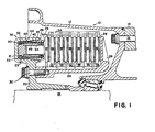
- numeral 10 designates an aircraft wheel and multiple disc brake thereof.
- the wheel is defined by two annular sections 12 and 14, only one of which is fully shown, fastened together by circumferentially spaced-apart bolts and nuts generally indicated by 16.
- the wheel is suitably journalled on a rotatably fixed axle 18 carried by conventional aircraft landing gear structure (not shown).
- An annular brake carrier 20 keyed to axle 18 is provided with a plurality of circumferentially spaced-apart casings 21, only one of which is shown, each having a cavity 22 vented via passage 23 to a source of pressurized fluid (not shown) controlled by the aircraft pilot.
- a torque tube 24 having an integral backing plate 26 is lined with frictional material 28 and fixedly secured to carrier 20 by a plurality of circumferentially spaced apart bolts 30.
- Axially spaced-apart annular brake rotor members 32 are keyed to a retaining member 34 fixedly secured to wheel section 12 and adapted to permit axial movement of the rotor members 32 relative to wheel section
- Annular brake stator members 35 having friction linings 36 secured to opposite faces thereof are keyed to torque tube 24 for axial movement.
- a pressure plate 37 is keyed to torque tube 24 for axial movement and, like backing plate 26 provided with lining 28, is adapted to be actuated by a plurality of piston means generally indicated by reference numeral 38, the piston means disposed in cavities 22 of casings 21.
- pressure plate 37 is urged toward backing plate 26 to compress the stacked stator and rotor members 35, 32 together to retard rotation of wheel sections 12 and 14.
- cavities 22 are each provided with a sleeve 40 threadedly engaged with casing 21, the sleeve 40 provided with an annular recess 42 containing an "O" ring or similar seal 44 as well as having a flange portion 46 adapted to be engaged by suitable wrench means (not shown) for assembly and disassembly purposes.
- the sleeve 40 has a reduced diameter inner shoulder 43 disposed adjacent the open end of cavity 22 where sleeve 40 threadedly engages casing 21. Located adjacent the inner shoulder 43 is recess 47 receiving annular seal means 48 therein.
- a fluid pressure actuated cylinder 50 having a diameter smaller than the interior diameter of sleeve 40 is slidably received within the interior of sleeve 40.
- Cylinder 50 Located at the closed end of casing 21 is an enlarged cylinder diameter shoulder 52 and disposed diagonally from a reduced cylinder diameter inner shoulder 54 located at the open end of cavity 22.
- Cylinder 50 is designed for axial travel outwardly of cavity 22 during which it is slidably engaged with the inner surface 49 of sleeve 40, the axial travel being limited by the engagement of enlarged diameter shoulder 52 with the reduced diameter inner shoulder 43 of sleeve 40.
- Figure 2 illustrates a breakable shear ring 90 fixedly received in recess 41 of sleeve 40.
- Cylinder 50 includes an outer shoulder 56 which engages the shear ring 90 to maintain the cylinder 50 at its initial axial position. Cylinder 50 also includes an annular opening 55 receiving an annular wiper seal therein for engagement with the outer surface of a piston 78 to preclude contaminants from entering between the adjacent surfaces of cylinder 50 and piston 78.
- Piston 78 slidably engages cylinder 50.
- Piston 78 includes an enlarged diameter rim shoulder 80 having an annular recess receiving annular 0-ring or fluid seal 82 therein for engagement with the inner surface of cylinder 50.
- the fluid seal 82 resists fluid leakage between the adjacent surfaces of cylinder 50 and piston 78.
- piston means 38 is adapted to be assembled as a unit and subsequently positioned in cavity 22 by screwing sleeve 40 therein.
- a brake application by the aircraft pilot results in pressurization of fluid supplied to cavities 22 and subsequent equal pressurization of pistons 78 which move away from the respective closed ends of casings 21 to compress rotor members 32 and stator members 35 together to produce the desired braking action of wheel sections 12 and 14.
- Each piston 78 travels axially outwardly of the associated cavity 22 and, as the brake linings 28 wear down during repeated engagement with rotor members 32, the piston 78 is displaced axially a further distance until enlarged diameter rim shoulder 80 engages the reduced diameter inner shoulder 54 of cylinder 50.
- piston 78 cannot be displaced axially any further to the right in the direction of arrow 100 of Figure 2, because shear ring 90 maintains cylinder 50 axially fixed relative to sleeve 40 and shoulder 54 maintains the extended axial position of piston 78.
- Shear ring 90 is designed such that fluid pressure acting upon the end wall 83 of piston 78 combined with fluid pressure acting upon the surface area of end 51 of cylinder 50 cause the shear ring 90 to fail or break and thereby release cylinder 50 for further axial movement in the direction of movement of the piston 78.
- the cylinder 50 moves immediately to the right in direction of arrow 100 whereupon shoulder 52 engages shoulder 43 of sleeve 40, and thus provides for extended travel of piston 78 (see Figure 2A).
- piston 78 is extended such that shoulder 52 of cylinder 50 will engage sleeve shoulder 43 before engaging pressure plate 37.
- the graph illustrates the drop in brake torque as a result of the force required to break the shear ring after engagement of rim shoulder 80 with reduced diameter inner shoulder 54 of cylinder 50.
- Figure 3 illustrates, in general terms, the brake torque (curve m-n) which may occur as the brake linings 28 are worn.
- the brake torque may decrease slightly as the pistons are extended further axially due to brake wear, with the brake actuation force remaining relatively constant during this period.
- the actuation force and brake torque both dip momentarily when the shear ring 90 fails which then permits the conjoint axial displacement of cylinder 50 and piston 78. This produces a momentary or transient increase in actuating force and brake torque as sleeve 50 and piston 78 act conjointly against pressure plate 37, in response to the fluid pressure acting upon the opposite ends of the sleeve and piston.
- actuation force and brake torque are illustrated by the momentary jump in both curves, after which both the actuation force and brake torque remain at relatively constant levels as the piston engages pressure plate 37.
- the area of end 51 of cylinder 50 is kept at a minimum value, i.e., a small end thickness of cylinder 50, in order to minimize the negative dip in the actuation force and brake torque curves.
- Shear rings 90 may comprise O grade pure aluminum and have a thickness of thirty to forty thousands of an inch.
- the graph of Figure 4 illustrates the change in brake pressure (actuation force) and brake torque versus time during a rejected takeoff test.
- the graph of Figure 4 illustrates the operation of seven pistons (#1 - #7) of a single aircraft brake assembly, during a rejected takeoff test.
- the brake experiences very small and temporary decreases in both brake pressure and brake torque when the respective shear rings fail due to the combined pressure acting upon the pistons and cylinders. These failures of the respective shear rings occur at different times during the rejected takeoff test. It was found that the stopping distance during a rejected takeoff test for the extensible piston of the present invention was less than for a like RTO test utilizing conventional pistons.
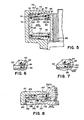
- Figure 5 illustrates the positioning of the shear ring 90 at an interior position of cavity 22.
- Sleeve 40 fixedly receives shear ring 90 in a recess adjacent its interior end, whereby ring 90 engages enlarged diameter shoulder 52 of cylinder 50.
- fluid pressure displaces axially piston 78 in the direction of arrow 200, and the brake linings 28, 36 wear to the extent that rim shoulder 80 of piston 78 engages reduced diameter inner shoulder 54 of cylinder 50, the combined fluid pressure acting upon the piston and sleeve causes shear ring 90 to break.
- Cylinder 50 is displaced axially and simultaneously shoulder 52 moves the broken portion(s) of shear ring 90 in the direction of arrow 200 until enlarged diameter shoulder 52 biases the broken portion(s) against the reduced diameter inner shoulder 43 which restrains cylinder 50 from any further axial movement.
- Shear ring 90 may also be modified in a number of ways in order to effect failure at a predetermined fluid pressure acting upon the piston and cylinder.
- Figure 6 illustrates shear ring 90 being fixedly secured in a recess of sleeve 40 and engaging outer shoulder 56 of cylinder 50, in the same manner as illustrated in Figures 1-2.
- shear ring 90 includes a notch 92 which structurally weakens the ring so that it will fail at a predetermined fluid pressure acting upon the piston and cylinder.
- the shear ring illustrated by Figure 6 can be positioned either interiorily or exteriorily of piston means 38, as illustrated by Figures 1, 2 and 5, the particular location of the ring being a matter of choice for the particular application.
- Figure 7 illustrates another embodiment of the present invention. Illustrated in schematic representation is a portion of the sleeve 40 including a recess 45 receiving a displaceable stop ring 94.
- the displaceable stop ring 94 engages shoulder 56 of cylinder 50, and when the combined fluid pressure acting upon the cylinder and piston reaches a sufficient, predetermined magnitude, displaceable stop ring 94 is displaced from recess 45 to release cylinder 50 for axial extension in the direction arrow 300.
- the displaceable stop ring 94 is displaced in the direction of the dotted line figures illustrating the axial positions of the stop ring, and stop ring 94 may be located either interiorily or exteriorily of piston means 38, in accordance with illustrations of Figures 1, 2, and 5, the particular location of the stop ring being a matter of choice according to the application and customer needs.
- FIG. 8 Another displaceable stop for retaining the cylinder of the piston means is illustrated in Figure 8.
- Casing 121 provides a cavity 122 including therein piston means 178.
- a sleeve 140 is threadedly received in the casing 121, and includes a reduced diameter inner shoulder 143 at its exterior end 188. Located within end 188 is recess 173 receiving a coil spring 186 therein. The coil spring 186 biases pin 184 and separate pin 185 radially inwardly through cylinder opening 157 of cylinder 150 and toward piston 178.
- Piston 178 includes an enlarged diameter rim shoulder 180 having a ramp 181.
- Figure 8 also illustrates a feature for preventing the loss of hydraulic fluid should the aircraft hydraulic system malfunction.
- fluid pressure in cavity 22 is increased as required in order to overcome the running clearance and press the rotors and stators together for the desired braking effect.
- the fluid pressure in cavity 122 returns to a "residual" value which is low enough to release clamping forces on the rotors and stators, but still greater than zero, typically 50 to 300 psig (345 to 2070 Pa). If fluid pressure in cavity 122 is lost, it is conceivable that dynamic and static forces could move piston 178 backwards relative to cylinder 150 to the extent that piston seal 182 is no longer compressed by the inner sealing surface of cylinder 150.
- snap ring 198 is inserted into the interior end of cylinder 150. Snap ring 198 prevents excessive backward movement of piston 178, thereby ensuring that seal 182 maintains fluid pressure in cavity 122.
- the snap ring 198 may be utilized in many extensible piston devices.
Description
- This invention relates to an extensible piston with a breakable or displaceable coupler which releases a cylinder for axial travel in a direction of movement of the extensible piston.
- The present invention relates to an aircraft brake adjuster, and more specifically to fluid pressure actuated pistons having an extended range of travel. Pistons having an extended range of travel are also known as extensible pistons are described in the following patents: Price U. S. Patent No. 4,006,669 issued February 8,1977 and entitled "Piston and Extensible Cylinder Therefor"; Ditlinger U. S. Patent No. 4,208,952 issued June 24,1980 and entitled "Piston with Extended Axial Travel"; and Massing U. S. Patent No. 4,249,458 issued February 10, 1981 and entitled "Piston and Extensible Cylinder Therefor". These prior constructions have utilized a telescoping cylinder disposed about the piston in order to provide for the extended range of piston travel, but have the disadvantage of providing greater actuating force at one time or another because of the differential areas of the cylinder and piston utilized during actuation of the brake. The area of the end of the telescoping cylinder acts as a piston until the cylinder extends and engages a stop. The result is that the brake can have too great an actuating force during part of its life or too small an actuating force during part of its life, depending upon the design of the particular brake. Providing compensation for the differential forces acting upon the piston and cylinder has involved the use of mechanical and hydraulic schemes which lessen the actuating force when the outer telescopic sleeve is operative. These compensation devices and designs have often times displayed erratic effects at the cylinder release transition point or provide compensation which is effective at one pressure only.
- It is an object of the present invention to provide a telescoping cylindrical sleeve which is held fixed relative to the brake carrier or casing by a locking mechanism until the piston is fully extended. At full extension of the piston, the locking mechanism releases the telescoping cylinder which immediately extends to its fully extended position against a stop and thereby provides the piston with another length of available travel without the utilization of any differential piston area.
- The present invention comprises a fluid pressure actuated piston slidably carried in a fluid pressure actuated cylinder which, in turn, is slidably carried in a fixed carrier or casing. Lateral movement of the cylinder is resisted by a breakable or displaceable coupler which engages a shoulder of the cylinder. Fluid pressure acting upon the cylinder and piston causes the coupler to break or be displaced and release the cylinder for axial movement in the direction of movement of the pressure responsive piston.
- The invention provides a savings in weight because the construction permits utilization of a shorter torque tube design or structure, also provides an increased heat sink envelope potential, a momentary drop or dip in the actuating force or torque during failure or displacement of the coupler which has a negligible affect upon brake performance and may actually improve the stopping distance, improves the performance of the brake in comparison to a brake using conventional pistons, and provides a simplified design for easily manufactured and assembled parts of an aircraft brake.
- The invention is described in detail below with reference to the drawings which illustrate several embodiments in which:
- Figure 1 is a sectional schematic representation of a conventional aircraft wheel and disc brake assembly embodying the present invention;
- Figure 2 is a sectional view of one embodiment of the present invention shown in enlarged form and removed from the wheel and disc brake of Figure 1;
- Figure 2A illustrates the brake of Figure 2 after release of the telescoping cylinder;
- Figure 3 is a graph illustrating actuation force and brake torque versus piston travel;
- Figure 4 is a graph illustrating brake pressure and torque versus time for the performance of seven pistons in an aircraft disc brake assembly;
- Figure 5 is a sectional view of another embodiment of the present invention shown in enlarged form;
- Figure 6 is a sectional view of another embodiment of the present invention shown in enlarged form;
- Figure 7 is a sectional view of another embodiment of the present invention comprising a displaceable stop; and
- Figure 8 is an embodiment of the present invention comprising a displaceable stop biased radially inwardly by resilient means.
- Referring to Figure 1,
numeral 10 designates an aircraft wheel and multiple disc brake thereof. The wheel is defined by twoannular sections axle 18 carried by conventional aircraft landing gear structure (not shown). Anannular brake carrier 20 keyed toaxle 18 is provided with a plurality of circumferentially spaced-apart casings 21, only one of which is shown, each having acavity 22 vented viapassage 23 to a source of pressurized fluid (not shown) controlled by the aircraft pilot. Atorque tube 24 having anintegral backing plate 26 is lined withfrictional material 28 and fixedly secured tocarrier 20 by a plurality of circumferentially spaced apartbolts 30. Axially spaced-apart annular brake rotor members 32 are keyed to a retainingmember 34 fixedly secured towheel section 12 and adapted to permit axial movement of the rotor members 32 relative to wheel section - 12. Annular
brake stator members 35 havingfriction linings 36 secured to opposite faces thereof are keyed totorque tube 24 for axial movement. Apressure plate 37 is keyed totorque tube 24 for axial movement and, likebacking plate 26 provided withlining 28, is adapted to be actuated by a plurality of piston means generally indicated byreference numeral 38, the piston means disposed incavities 22 ofcasings 21. Upon energization of the piston means 38,pressure plate 37 is urged towardbacking plate 26 to compress the stacked stator androtor members 35, 32 together to retard rotation ofwheel sections - Referring to Figures 1-2A,
cavities 22 are each provided with asleeve 40 threadedly engaged withcasing 21, thesleeve 40 provided with anannular recess 42 containing an "O" ring orsimilar seal 44 as well as having aflange portion 46 adapted to be engaged by suitable wrench means (not shown) for assembly and disassembly purposes. Thesleeve 40 has a reduced diameterinner shoulder 43 disposed adjacent the open end ofcavity 22 wheresleeve 40 threadedly engagescasing 21. Located adjacent theinner shoulder 43 is recess 47 receiving annular seal means 48 therein. - A fluid pressure actuated
cylinder 50 having a diameter smaller than the interior diameter ofsleeve 40 is slidably received within the interior ofsleeve 40. Located at the closed end ofcasing 21 is an enlargedcylinder diameter shoulder 52 and disposed diagonally from a reduced cylinder diameterinner shoulder 54 located at the open end ofcavity 22.Cylinder 50 is designed for axial travel outwardly ofcavity 22 during which it is slidably engaged with theinner surface 49 ofsleeve 40, the axial travel being limited by the engagement of enlargeddiameter shoulder 52 with the reduced diameterinner shoulder 43 ofsleeve 40. Figure 2 illustrates abreakable shear ring 90 fixedly received in recess 41 ofsleeve 40.Cylinder 50 includes anouter shoulder 56 which engages theshear ring 90 to maintain thecylinder 50 at its initial axial position.Cylinder 50 also includes anannular opening 55 receiving an annular wiper seal therein for engagement with the outer surface of apiston 78 to preclude contaminants from entering between the adjacent surfaces ofcylinder 50 andpiston 78. - The cup-
shaped piston 78 slidably engagescylinder 50. Piston 78 includes an enlargeddiameter rim shoulder 80 having an annular recess receiving annular 0-ring orfluid seal 82 therein for engagement with the inner surface ofcylinder 50. Thefluid seal 82 resists fluid leakage between the adjacent surfaces ofcylinder 50 andpiston 78. - It should be noted that the above-described structure of piston means 38 is adapted to be assembled as a unit and subsequently positioned in
cavity 22 byscrewing sleeve 40 therein. - Assuming that the brake apparatus of Figure 2 is in position as shown in Figure 1, a brake application by the aircraft pilot results in pressurization of fluid supplied to
cavities 22 and subsequent equal pressurization ofpistons 78 which move away from the respective closed ends ofcasings 21 to compress rotor members 32 andstator members 35 together to produce the desired braking action ofwheel sections piston 78 travels axially outwardly of the associatedcavity 22 and, as thebrake linings 28 wear down during repeated engagement with rotor members 32, thepiston 78 is displaced axially a further distance until enlargeddiameter rim shoulder 80 engages the reduced diameterinner shoulder 54 ofcylinder 50. At this point,piston 78 cannot be displaced axially any further to the right in the direction ofarrow 100 of Figure 2, becauseshear ring 90 maintainscylinder 50 axially fixed relative tosleeve 40 andshoulder 54 maintains the extended axial position ofpiston 78.Shear ring 90 is designed such that fluid pressure acting upon theend wall 83 ofpiston 78 combined with fluid pressure acting upon the surface area ofend 51 ofcylinder 50 cause theshear ring 90 to fail or break and thereby releasecylinder 50 for further axial movement in the direction of movement of thepiston 78. Thecylinder 50 moves immediately to the right in direction ofarrow 100 whereuponshoulder 52 engagesshoulder 43 ofsleeve 40, and thus provides for extended travel of piston 78 (see Figure 2A). At the time of shear ring failure,piston 78 is extended such thatshoulder 52 ofcylinder 50 will engagesleeve shoulder 43 before engagingpressure plate 37. - At or just prior to the failure of
shear ring 90, there occurs a momentary drop in the actuating force and brake torque acting upon the stator and rotor members providing braking. This momentary, slight drop in the brake torque occurs because the piston is momentarily restrained byshear ring 90 from further axial travel against thepressure plate 37, and when theshear ring 90 fails there is flow of fluid into thecavity 22 to compensate for the displacement of the cylinder in the direction ofarrow 100. Referring to Figure 4, the graph illustrates the drop in brake torque as a result of the force required to break the shear ring after engagement ofrim shoulder 80 with reduced diameterinner shoulder 54 ofcylinder 50. Figure 3 illustrates, in general terms, the brake torque (curve m-n) which may occur as thebrake linings 28 are worn. The brake torque may decrease slightly as the pistons are extended further axially due to brake wear, with the brake actuation force remaining relatively constant during this period. When brake wear O-X has occurred, the actuation force and brake torque both dip momentarily when theshear ring 90 fails which then permits the conjoint axial displacement ofcylinder 50 andpiston 78. This produces a momentary or transient increase in actuating force and brake torque assleeve 50 andpiston 78 act conjointly againstpressure plate 37, in response to the fluid pressure acting upon the opposite ends of the sleeve and piston. The increases in actuation force and brake torque are illustrated by the momentary jump in both curves, after which both the actuation force and brake torque remain at relatively constant levels as the piston engagespressure plate 37. The area ofend 51 ofcylinder 50 is kept at a minimum value, i.e., a small end thickness ofcylinder 50, in order to minimize the negative dip in the actuation force and brake torque curves. - It has been found that the negative dip in each curve of Figure 3 is insignificant in practical application. Rejected takeoff (RTO) tests for new brakes require that certain parameters be met by aircraft brakes. It has been found that the new brake RTO requirements would be achieved with the piston means of the present invention, and that partially worn or worn brake RTO performance would generally be unchanged. The reduction in actuating force at the brake wear point X, and the momentary increase in both the actuation force and brake torque as illustrated in Figure 3, are of little practical significance because, due to manufacturing tolerances, all of the brakes on an aircraft would not wear uniformly and therefore failures of the shear rings occur at different landings for different brakes of the aircraft. Additionally, the various shear rings will fail at slightly different stroke positions in a given brake, coupled with different brakes experiencing failure of the respective shear rings during different landings.
- During rejected takeoff tests, the piston stroke is large in comparison to the small displacement involved in loading and causing failure of the
shear ring 90. A momentary spike in the force actuation curve and brake torque curve would be negligible in comparison to the increased actuation force and torque which results. The RTO would be essentially unaffected and possibly enhanced due to the pulse or spike which tends to overcome the keyway friction experienced by rotors 32 andstators 35. - In the design of the
shear ring 90, it would be desirable to have the release force of telescopingcylinder 50 be as low as possible, with thering 90 still able to withstand vibration and environmental effects such as temperature changes, during its life. Shear rings 90 may comprise O grade pure aluminum and have a thickness of thirty to forty thousands of an inch. - Rejected takeoff tests have determined that the drop in brake torque during failure of the shear ring has a negligible effect on aircraft brake performance. The graph of Figure 4 illustrates the change in brake pressure (actuation force) and brake torque versus time during a rejected takeoff test. As explained above, because of manufacturing tolerances the
brake linings - Referring now to Figure 5, there is illustrated an alternative embodiment of the invention illustrated in Figure 2. Figure 5 illustrates the positioning of the
shear ring 90 at an interior position ofcavity 22.Sleeve 40 fixedly receivesshear ring 90 in a recess adjacent its interior end, wherebyring 90 engagesenlarged diameter shoulder 52 ofcylinder 50. When fluid pressure displaces axiallypiston 78 in the direction ofarrow 200, and thebrake linings shoulder 80 ofpiston 78 engages reduced diameterinner shoulder 54 ofcylinder 50, the combined fluid pressure acting upon the piston and sleeve causesshear ring 90 to break.Cylinder 50 is displaced axially and simultaneously shoulder 52 moves the broken portion(s) ofshear ring 90 in the direction ofarrow 200 untilenlarged diameter shoulder 52 biases the broken portion(s) against the reduced diameterinner shoulder 43 which restrainscylinder 50 from any further axial movement. By placingshear ring 90 interiorily of piston means 38, the risk of damage due to foreign objects located about the exterior ofpiston 78 is eliminated. -
Shear ring 90 may also be modified in a number of ways in order to effect failure at a predetermined fluid pressure acting upon the piston and cylinder. Figure 6 illustratesshear ring 90 being fixedly secured in a recess ofsleeve 40 and engagingouter shoulder 56 ofcylinder 50, in the same manner as illustrated in Figures 1-2. However,shear ring 90 includes anotch 92 which structurally weakens the ring so that it will fail at a predetermined fluid pressure acting upon the piston and cylinder. It should be clearly understood that the shear ring illustrated by Figure 6 can be positioned either interiorily or exteriorily of piston means 38, as illustrated by Figures 1, 2 and 5, the particular location of the ring being a matter of choice for the particular application. - Figure 7 illustrates another embodiment of the present invention. Illustrated in schematic representation is a portion of the
sleeve 40 including arecess 45 receiving adisplaceable stop ring 94. Thedisplaceable stop ring 94 engagesshoulder 56 ofcylinder 50, and when the combined fluid pressure acting upon the cylinder and piston reaches a sufficient, predetermined magnitude,displaceable stop ring 94 is displaced fromrecess 45 to releasecylinder 50 for axial extension in thedirection arrow 300. Thedisplaceable stop ring 94 is displaced in the direction of the dotted line figures illustrating the axial positions of the stop ring, and stopring 94 may be located either interiorily or exteriorily of piston means 38, in accordance with illustrations of Figures 1, 2, and 5, the particular location of the stop ring being a matter of choice according to the application and customer needs. - Another displaceable stop for retaining the cylinder of the piston means is illustrated in Figure 8. The numerals of Figure 8 have been increased by 100 where there are structural elements in common with those illustrated in the previous Figures. Casing 121 provides a
cavity 122 including therein piston means 178. Asleeve 140 is threadedly received in thecasing 121, and includes a reduced diameterinner shoulder 143 at itsexterior end 188. Located withinend 188 isrecess 173 receiving acoil spring 186 therein. Thecoil spring 186biases pin 184 andseparate pin 185 radially inwardly through cylinder opening 157 ofcylinder 150 and toward piston 178. Piston 178 includes an enlargeddiameter rim shoulder 180 having aramp 181. In operation, as piston 178 is extended axially in the direction of arrow 400,ramp 181 engagespin 185 to bias pins 184 and 185 radially outwardly in the direction of arrow 500 so thatpin 184 retracts intorecess opening 173.Pins pin 185 displacespin 184 radially outwardly intorecess 173, theinterface 187 between the pins approaches theouter surface 158 ofcylinder 150. Wheninterface 187 reaches theouter surface 158 ofcylinder 150 wherebypin 184 no longer extends intocylinder opening 157,cylinder 150 is no longer retained bypin 184 and extends axially untilenlarged diameter shoulder 152 engages reduced diameterinner shoulder 143, thereby providing for extended axial travel of the piston 178. - Figure 8 also illustrates a feature for preventing the loss of hydraulic fluid should the aircraft hydraulic system malfunction. During brake actuation, fluid pressure in
cavity 22 is increased as required in order to overcome the running clearance and press the rotors and stators together for the desired braking effect. When the brakes are released, the fluid pressure incavity 122 returns to a "residual" value which is low enough to release clamping forces on the rotors and stators, but still greater than zero, typically 50 to 300 psig (345 to 2070 Pa). If fluid pressure incavity 122 is lost, it is conceivable that dynamic and static forces could move piston 178 backwards relative tocylinder 150 to the extent thatpiston seal 182 is no longer compressed by the inner sealing surface ofcylinder 150. Under such circumstances, leakage of hydraulic fluid could occur. To prevent fluid leakage,snap ring 198 is inserted into the interior end ofcylinder 150.Snap ring 198 prevents excessive backward movement of piston 178, thereby ensuring thatseal 182 maintains fluid pressure incavity 122. Thesnap ring 198 may be utilized in many extensible piston devices.
Claims (9)
Applications Claiming Priority (2)
| Application Number | Priority Date | Filing Date | Title |
|---|---|---|---|
| US06/578,711 US4570531A (en) | 1984-02-09 | 1984-02-09 | Extensible piston with breakable or displaceable coupler |
| US578711 | 1984-02-09 |
Publications (2)
| Publication Number | Publication Date |
|---|---|
| EP0154769A1 EP0154769A1 (en) | 1985-09-18 |
| EP0154769B1 true EP0154769B1 (en) | 1988-12-07 |
Family
ID=24313977
Family Applications (1)
| Application Number | Title | Priority Date | Filing Date |
|---|---|---|---|
| EP85100139A Expired EP0154769B1 (en) | 1984-02-09 | 1985-01-08 | Extensible piston with breakable or displaceable coupler |
Country Status (5)
| Country | Link |
|---|---|
| US (1) | US4570531A (en) |
| EP (1) | EP0154769B1 (en) |
| JP (1) | JPS60184733A (en) |
| CA (1) | CA1231290A (en) |
| DE (1) | DE3566718D1 (en) |
Families Citing this family (11)
| Publication number | Priority date | Publication date | Assignee | Title |
|---|---|---|---|---|
| US4798052A (en) * | 1987-05-08 | 1989-01-17 | Allied-Signal Inc. | Constant-clearance brake piston system with braking pressure intensifier |
| US5072811A (en) * | 1989-12-27 | 1991-12-17 | Aircraft Braking Systems Corporation | Telescopic brake piston |
| US5172793A (en) * | 1990-06-21 | 1992-12-22 | Allied-Signal Inc. | Vehicle brake with brake cylinder bore insert |
| DE4140279C1 (en) * | 1991-12-06 | 1993-04-29 | Mercedes-Benz Aktiengesellschaft, 7000 Stuttgart, De | |
| JPH087332Y2 (en) * | 1992-04-13 | 1996-03-04 | ホシザキ電機株式会社 | refrigerator |
| US5485902A (en) * | 1994-08-05 | 1996-01-23 | Alliedsignal Inc. | Aircraft brake piston hydraulic adjuster assembly |
| US5964321A (en) * | 1996-04-26 | 1999-10-12 | Hayes Brake, Inc. | Ball joint piston bore caliper |
| JP5039530B2 (en) * | 2007-12-20 | 2012-10-03 | 三菱重工業株式会社 | Wet multi-plate brake device for vehicles |
| US8360215B2 (en) | 2009-01-09 | 2013-01-29 | Ausco Products, Inc. | Two-stage slave cylinder |
| US9132809B2 (en) * | 2012-10-18 | 2015-09-15 | Performance Friction | Integrated parking brake for disc brake |
| JP6950503B2 (en) * | 2017-12-08 | 2021-10-13 | トヨタ自動車株式会社 | Hydraulic braking system |
Family Cites Families (10)
| Publication number | Priority date | Publication date | Assignee | Title |
|---|---|---|---|---|
| DE21377C (en) * | A. HUBER in Cöln | Innovation on ventilation caps | ||
| US3915063A (en) * | 1974-06-19 | 1975-10-28 | Bendix Corp | Extensible piston |
| US4006669A (en) * | 1975-05-19 | 1977-02-08 | The Bendix Corporation | Piston and extensible cylinder therefor |
| US4075929A (en) * | 1976-01-28 | 1978-02-28 | The United States Of America As Represented By The Secretary Of The Air Force | Three stage thrusting device |
| US4208952A (en) * | 1976-12-27 | 1980-06-24 | The Bendix Corporation | Piston with extended axial travel |
| GB1603609A (en) * | 1977-04-14 | 1981-11-25 | Chembiomed Ltd | O-protected 2-azido-2-deoxy-glycosyl nitrates |
| US4195714A (en) * | 1977-08-22 | 1980-04-01 | The Bendix Corporation | Piston and extensible cylinder therefor |
| US4249458A (en) * | 1979-05-11 | 1981-02-10 | The Bendix Corporation | Piston and extensible cylinder therefor |
| DE3016279A1 (en) * | 1980-04-28 | 1981-10-29 | Alfred Teves Gmbh, 6000 Frankfurt | Coaxial twin pistons in hydraulic brake cylinder - are radially coupled by friction segments, resulting in being subjected to similar hydraulic pressure |
| DE3114525A1 (en) * | 1981-04-10 | 1982-11-04 | Gewerkschaft Eisenhütte Westfalia, 4670 Lünen | HYDRAULIC PRESS CYLINDER FOR PIPE PRESSING AND THE LIKE |
-
1984
- 1984-02-09 US US06/578,711 patent/US4570531A/en not_active Expired - Fee Related
-
1985
- 1985-01-08 DE DE8585100139T patent/DE3566718D1/en not_active Expired
- 1985-01-08 EP EP85100139A patent/EP0154769B1/en not_active Expired
- 1985-02-08 JP JP60022129A patent/JPS60184733A/en active Pending
- 1985-02-08 CA CA000473918A patent/CA1231290A/en not_active Expired
Also Published As
| Publication number | Publication date |
|---|---|
| EP0154769A1 (en) | 1985-09-18 |
| DE3566718D1 (en) | 1989-01-12 |
| US4570531A (en) | 1986-02-18 |
| JPS60184733A (en) | 1985-09-20 |
| CA1231290A (en) | 1988-01-12 |
Similar Documents
| Publication | Publication Date | Title |
|---|---|---|
| EP0890037B1 (en) | Multi-disc brake actuator for vibration damping | |
| EP0941419B1 (en) | Multi-disk brake actuator for vibration damping | |
| US4006669A (en) | Piston and extensible cylinder therefor | |
| EP0154769B1 (en) | Extensible piston with breakable or displaceable coupler | |
| US3376959A (en) | Automatic brake adjuster mechanism | |
| US5205382A (en) | Aircraft brake | |
| US5219046A (en) | Aircraft brake | |
| US4815359A (en) | Compact brake piston return mechanism | |
| US3729072A (en) | Brake adjuster | |
| US4587888A (en) | Extensible piston with breakable or displaceable coupler | |
| US4249458A (en) | Piston and extensible cylinder therefor | |
| US4195714A (en) | Piston and extensible cylinder therefor | |
| EP0260412B1 (en) | Compact brake piston-return mechanism | |
| EP1122455B1 (en) | Reduced drag wet disc brake assembly | |
| GB2099524A (en) | Disc brake | |
| US3887042A (en) | Piston and extensible cylinder therefor | |
| EP0227315B1 (en) | Improvements relating to adjusters | |
| GB2026632A (en) | Brake wear adjusters | |
| RU2143381C1 (en) | Multi-disk brake | |
| EP0480358A1 (en) | Aircraft brake | |
| US4208952A (en) | Piston with extended axial travel | |
| EP0074734B1 (en) | Actuator for brakes or the like | |
| EP0495311A1 (en) | Brake actuator | |
| EP0229403B1 (en) | Torque limited brake | |
| EP0110742B1 (en) | Disc brake thrust collar assembly |
Legal Events
| Date | Code | Title | Description |
|---|---|---|---|
| PUAI | Public reference made under article 153(3) epc to a published international application that has entered the european phase |
Free format text: ORIGINAL CODE: 0009012 |
|
| AK | Designated contracting states |
Designated state(s): DE FR GB IT |
|
| 17P | Request for examination filed |
Effective date: 19860217 |
|
| 17Q | First examination report despatched |
Effective date: 19870625 |
|
| RAP1 | Party data changed (applicant data changed or rights of an application transferred) |
Owner name: ALLIED-SIGNAL INC. |
|
| ITF | It: translation for a ep patent filed |
Owner name: INTERPATENT ST.TECN. BREV. |
|
| GRAA | (expected) grant |
Free format text: ORIGINAL CODE: 0009210 |
|
| AK | Designated contracting states |
Kind code of ref document: B1 Designated state(s): DE FR GB IT |
|
| REF | Corresponds to: |
Ref document number: 3566718 Country of ref document: DE Date of ref document: 19890112 |
|
| ET | Fr: translation filed | ||
| PLBE | No opposition filed within time limit |
Free format text: ORIGINAL CODE: 0009261 |
|
| STAA | Information on the status of an ep patent application or granted ep patent |
Free format text: STATUS: NO OPPOSITION FILED WITHIN TIME LIMIT |
|
| 26N | No opposition filed | ||
| ITTA | It: last paid annual fee | ||
| PGFP | Annual fee paid to national office [announced via postgrant information from national office to epo] |
Ref country code: FR Payment date: 19911223 Year of fee payment: 8 |
|
| PGFP | Annual fee paid to national office [announced via postgrant information from national office to epo] |
Ref country code: GB Payment date: 19920103 Year of fee payment: 8 |
|
| PGFP | Annual fee paid to national office [announced via postgrant information from national office to epo] |
Ref country code: DE Payment date: 19920131 Year of fee payment: 8 |
|
| PG25 | Lapsed in a contracting state [announced via postgrant information from national office to epo] |
Ref country code: GB Effective date: 19930108 |
|
| GBPC | Gb: european patent ceased through non-payment of renewal fee |
Effective date: 19930108 |
|
| PG25 | Lapsed in a contracting state [announced via postgrant information from national office to epo] |
Ref country code: FR Effective date: 19930930 |
|
| PG25 | Lapsed in a contracting state [announced via postgrant information from national office to epo] |
Ref country code: DE Effective date: 19931001 |
|
| REG | Reference to a national code |
Ref country code: FR Ref legal event code: ST |