EP0154732A1 - Physiotherapeutisches Gerät - Google Patents
Physiotherapeutisches Gerät Download PDFInfo
- Publication number
- EP0154732A1 EP0154732A1 EP84301558A EP84301558A EP0154732A1 EP 0154732 A1 EP0154732 A1 EP 0154732A1 EP 84301558 A EP84301558 A EP 84301558A EP 84301558 A EP84301558 A EP 84301558A EP 0154732 A1 EP0154732 A1 EP 0154732A1
- Authority
- EP
- European Patent Office
- Prior art keywords
- shaft
- movement
- disc
- physical therapy
- lever arm
- Prior art date
- Legal status (The legal status is an assumption and is not a legal conclusion. Google has not performed a legal analysis and makes no representation as to the accuracy of the status listed.)
- Withdrawn
Links
- 238000000554 physical therapy Methods 0.000 title claims abstract description 26
- 239000012530 fluid Substances 0.000 claims description 11
- 230000002093 peripheral effect Effects 0.000 claims description 6
- 238000005096 rolling process Methods 0.000 claims 1
- 238000011282 treatment Methods 0.000 description 6
- 230000000087 stabilizing effect Effects 0.000 description 4
- 230000000881 depressing effect Effects 0.000 description 3
- 238000010276 construction Methods 0.000 description 2
- 210000000245 forearm Anatomy 0.000 description 2
- 210000000707 wrist Anatomy 0.000 description 2
- 230000000994 depressogenic effect Effects 0.000 description 1
- 230000000007 visual effect Effects 0.000 description 1
Images

Classifications
-
- B—PERFORMING OPERATIONS; TRANSPORTING
- B60—VEHICLES IN GENERAL
- B60B—VEHICLE WHEELS; CASTORS; AXLES FOR WHEELS OR CASTORS; INCREASING WHEEL ADHESION
- B60B33/00—Castors in general; Anti-clogging castors
- B60B33/0078—Castors in general; Anti-clogging castors characterised by details of the wheel braking mechanism
- B60B33/0089—Castors in general; Anti-clogging castors characterised by details of the wheel braking mechanism acting on the floor
-
- A—HUMAN NECESSITIES
- A63—SPORTS; GAMES; AMUSEMENTS
- A63B—APPARATUS FOR PHYSICAL TRAINING, GYMNASTICS, SWIMMING, CLIMBING, OR FENCING; BALL GAMES; TRAINING EQUIPMENT
- A63B21/00—Exercising apparatus for developing or strengthening the muscles or joints of the body by working against a counterforce, with or without measuring devices
- A63B21/00058—Mechanical means for varying the resistance
- A63B21/00069—Setting or adjusting the resistance level; Compensating for a preload prior to use, e.g. changing length of resistance or adjusting a valve
- A63B21/00072—Setting or adjusting the resistance level; Compensating for a preload prior to use, e.g. changing length of resistance or adjusting a valve by changing the length of a lever
-
- A—HUMAN NECESSITIES
- A63—SPORTS; GAMES; AMUSEMENTS
- A63B—APPARATUS FOR PHYSICAL TRAINING, GYMNASTICS, SWIMMING, CLIMBING, OR FENCING; BALL GAMES; TRAINING EQUIPMENT
- A63B21/00—Exercising apparatus for developing or strengthening the muscles or joints of the body by working against a counterforce, with or without measuring devices
- A63B21/012—Exercising apparatus for developing or strengthening the muscles or joints of the body by working against a counterforce, with or without measuring devices using frictional force-resisters
- A63B21/015—Exercising apparatus for developing or strengthening the muscles or joints of the body by working against a counterforce, with or without measuring devices using frictional force-resisters including rotating or oscillating elements rubbing against fixed elements
-
- B—PERFORMING OPERATIONS; TRANSPORTING
- B21—MECHANICAL METAL-WORKING WITHOUT ESSENTIALLY REMOVING MATERIAL; PUNCHING METAL
- B21H—MAKING PARTICULAR METAL OBJECTS BY ROLLING, e.g. SCREWS, WHEELS, RINGS, BARRELS, BALLS
- B21H1/00—Making articles shaped as bodies of revolution
- B21H1/18—Making articles shaped as bodies of revolution cylinders, e.g. rolled transversely cross-rolling
-
- B—PERFORMING OPERATIONS; TRANSPORTING
- B23—MACHINE TOOLS; METAL-WORKING NOT OTHERWISE PROVIDED FOR
- B23P—METAL-WORKING NOT OTHERWISE PROVIDED FOR; COMBINED OPERATIONS; UNIVERSAL MACHINE TOOLS
- B23P15/00—Making specific metal objects by operations not covered by a single other subclass or a group in this subclass
- B23P15/24—Making specific metal objects by operations not covered by a single other subclass or a group in this subclass dies
-
- B—PERFORMING OPERATIONS; TRANSPORTING
- B23—MACHINE TOOLS; METAL-WORKING NOT OTHERWISE PROVIDED FOR
- B23H—WORKING OF METAL BY THE ACTION OF A HIGH CONCENTRATION OF ELECTRIC CURRENT ON A WORKPIECE USING AN ELECTRODE WHICH TAKES THE PLACE OF A TOOL; SUCH WORKING COMBINED WITH OTHER FORMS OF WORKING OF METAL
- B23H2200/00—Specific machining processes or workpieces
- B23H2200/30—Specific machining processes or workpieces for making honeycomb structures
-
- B—PERFORMING OPERATIONS; TRANSPORTING
- B60—VEHICLES IN GENERAL
- B60B—VEHICLE WHEELS; CASTORS; AXLES FOR WHEELS OR CASTORS; INCREASING WHEEL ADHESION
- B60B2200/00—Type of product being used or applied
- B60B2200/20—Furniture or medical appliances
- B60B2200/24—Beds
- B60B2200/242—Hospital beds
Definitions
- the present invention relates to a physical therapy apparatus which is adapted to provide adjustable exercise resistance for various portions of a user's body.
- a physical therapy apparatus which comprises a supporting frame, a shaft rotatably mounted to the supporting frame, and a lever arm fixed to the shaft and extending radially therefrom, with the lever arm having a free end adapted for engagement by the user and so that the user may pivot the lever arm and shaft about the axis of the shaft in a back and forth manner.
- This resistance imparting means comprises a pair of discs coaxially disposed about the shaft, a first one way clutch for rotating one of the discs with the shaft only upon rotation of the shaft in one direction, and a second one way clutch for rotating the other disc with the shaft only upon rotation of the shaft in the other direction.
- First and second disc engaging means are disposed adjacent respective ones of the discs for frictionally engaging the surface thereof, with each of the disc engaging means including means for separately adjusting the force of the frictional engagement with the surface of the associated disc so as to provide a separately adjustable resistance to the rotation of each disc, and thereby provide a separately adjustable resistance to movement of the lever arm in each direction.
- each of the disc engaging means comprises a piston, and a cylinder slideably mounting the piston therein for movement toward and away from the associated disc. Further, there is provided a hydraulic fluid filled chamber disposed in the associated cylinder on the side of the piston opposite the associated disc, and means are provided for adjusting the pressure of the hydraulic fluid in each of the chambers. In order to provide an indication of the force of the frictional engagement between the piston and disc, each of the disc engaging means is also provided with a pressure gauge which indicates the pressure of the hydraulic fluid therein.
- the preferred embodiment of the invention comprises a frame which permits the lever arm to be oriented in a variety of positions so as to permit exercise of various portions of the body, and further, a horizontal bracket is mounted to the frame so as to permit axial and rotational movement of the bracket with respect to the frame, and such that the bracket may be pressed upwardly against a bed frame or other horizontal surface to attach the apparatus to the bed frame or the like during use.
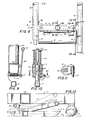
- the illustrated physical therapy apparatus includes an H-shaped base frame member 1 having parallel side members 2 joined by a cross member 3.
- the base frame member is supported on rollers 4.
- an H-shaped stabilizing or secondary base frame member 5 Underlying the base frame member 1 is an H-shaped stabilizing or secondary base frame member 5, which includes parallel side members 6 and a cross member 7.
- a depressing lever 9 is pivotally connected to the parallel members 2 of the base frame member 1 by the pins 8, and the depressing lever 9 includes a lever arm 10 adjacent each member 2 and a connecting bar 11.
- the lever arms 10 have nodules 10a on their lower edges and intermediate their ends, for contacting the cross member 7 of the frame member 5.
- a pair of vertical latching rods 12 are fixed to the cross member 7 of the stabilizing frame member 5, and each of the rods 12 extends upwardly through a guide sleeve 15 in the cross member 3 of the base frame member 1.
- Each rod 12 includes conical latching elements 13 forming latching shoulders 14, and each guide sleeve 15 is provided with a horizontal slot which receives a keeper plate 16 which is adapted to engage the latching elements 13.
- the two keeper plates are joined by a connecting bar 17 which extends parallel to the cross members 3 and 7.
- the connecting bar 17 is provided with spaced lever arms 18 which pivotally contact the cross mem-ber 3 intermediate their ends as shown in Figure 9.
- the connecting bar is also joined to the underside of the cross member 3 by appropriate springs 20 so that the keeper plates 16 are biased toward the latching elements 13.
- the upper ends of the lever arms 18 are joined by a cross bar 21.
- the upper ends of the latching rods 12 are provided with a coaxial bolt 22 and washer 23.
- a spring 24 Interposed between the washers 23 and the upper surface of the cross member 3 is a spring 24, so that the springs 24 urge the stabilizing frame member 5 upwardly.
- the depressing lever 9 is positioned so that its connecting bar 11 may be engaged by the user's foot, so as to be depressed into engagement with the cross member 7 of the stabilizing frame 5, to thereby move the frame member 5 downwardly against the underlying floor surface S and thereby lift the H-frame member 1 and rollers 4 from the surface S, note Figure 12.
- the keeper plates 16 engage the latching elements 13 of the rods 12, to retain the frame member 5 in the lowered position. Release of the frame member 5 is accomplished by foot engagement with the cross bar 21, which withdraws the keeper plates 16 from the elements 13.
- the springs 24 then lift the frame member 5 to its original raised position, causing the base frame member 1 and rollers 4 to again engage the ground surface S and support the apparatus.
- An upright post 25 is fixedly mounted to the cross member 3 of the base frame member, and an extension post 26 is slideably received in the tubular upright post 25 so as to permit relative axial movement and relative rotational movement therebetween.
- a split sleeve 58 ( Figures 2-4) at the upper end of the post, and which includes a pair of cam lugs 59.
- a locking handle 60 is pivotally mounted to the pin 62 which extends laterally through the cam lugs 59.
- the handle 60 includes parallel sides 61 for clamping the lugs laterally toward each other, to thereby close the sleeve 58 upon the extension 26, when the handle is pivoted downwardly to the position shown in the drawings.
- a tubular collar 27 is fixed to the upper free end of the extension 26, with the collar being oriented so as to define a horizontal axis.
- a horizontal tubular arm 28 extends coaxially through the collar 27 so as to permit relative axial movement and relative rotational position.
- the collar 27 is split, and it will be understood that the handle 55 permits the horizontal arm and collar to be releasably interconnected in a selected axial and rotational orientation by a structural arrangement corresponding to that shown in Figures 3 and 4.
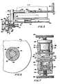
- a sleeve 29 is fixedly mounted at one end of the horizontal arm 28 and defines an axis A (Figure 1) which perpendicularly intersects the horizontal axis defined by the sleeve 27 and arm 28.
- a shaft 30 is rotatably mounted in the sleeve 29, and a lever arm 35, 36 is fixed to the extension 34 of the shaft 30.
- the lever arm extends radially with respect to the shaft 30 along the axis B ( Figure 5), and includes a free end having a transverse handle 37 adapted for engagement by the user, and so that the user may pivot the lever arm and the shaft 30 about the axis A of the sleeve 29 in a back and forth manner.
- the lever arm comprises a first inner segment 35 which is fixed to the extension 34, and a coaxial outer segment 36 so as to permit relative axial movement and relative rotational movement between the two segments.
- a handle 56 which also generally corresponds to the structure shown in Figures 3 and 4, is provided for releasably interconnecting the inner segment and the outer segment in a preselected axial and rotational orientation.
- the apparatus further includes means for imparting an adjustable resistance to the movement of the lever arm 35, 36 in each of the back and forth directions.
- This resistance imparting means includes a pair of discs 31 coaxially disposed about the shaft 30.
- the hubs of the discs 31 are illustrated in Figure 6, and each includes slots 32, with each slot receiving a clutch roller 33.
- the slots 32 are so configured and arranged that when the shaft 30 is rotated in one direction, one of the discs 31 rotates therewith, and when the shaft 30 is rotated in the opposite direction, the other disc 31 rotates therewith.
- the resistance imparting means further includes first and second disc engaging means disposed adjacent respective ones of the discs for frictionally engaging the surface thereof. More particularly, a housing 38 is secured to the sleeve 29 by a bracket 38a, and the housing 38 includes slots 39 which receive peripheral portions of respective ones of the discs 31. As best seen in Figure 7, the housing 38 defines a pair of oppositely directed coaxial cylinders 40, with each cylinder 40 being disposed along an axis parallel to the axis A of the shaft 30 and further being aligned with a peripheral surface portion of the associated disc 31. A piston 41 is slideably received in each cylinder for movement toward and away from the peripheral surface portion of the disc.
- the two cylinders 40 and pistons 41 are oriented in opposite directions, and the end face 42 of each piston is adapted to engage the surface of the associated disc 31. Also, each end face 42 is disposed in alignment with a back- . up pad 43 located on the opposite side of the associated disc 31.
- Each cylinder 40 is provided with an end plate 44 secured thereto by appropriate bolts (not shown). Each end plate 44 in turn mounts a pilot cylinder 45 which receives a pilot piston 46. Each end plate 44 is also provided with a threaded bore which is aligned with its pilot cylinder 45, and which receives a threaded shaft 47 having an outer end flange 48.
- the cylinders 40 further include a hydraulic fluid filled chamber disposed on the side of the piston opposite the associated disc 31, and the piston 46 and flange 48 thus permit the pressure of the hydraulic fluid in each of the chambers to be adjusted. More particularly, inward movement of the piston 46 in each cylinder increases the pressure therein, and thus increases the friction between the end face 42 of the piston 41 and its associated disc 31. Conversely, outward movement of the piston 46 reduces the force applied to the disc 31.
- Each of the fluid filled chambers is connected to a corresponding pressure gauge 49, so that the gauges visually indicate the pressure of the hydraulic fluid therein.
- the above described separately adjustable resistance imparting means for the two discs permits independent variation of the resistance of the shaft 30 and lever arm 35, 36 to angular movement in each direction. Also, the visual pressure indication provided by the two gauges 49 provides assurance that a desired amount of resistance is being applied in each direction. The gauges also facilitate the initial set up of the apparatus, and repeatability of the exercise program, for a particular user.
- the apparatus of the present invention further includes provision for releasably securing the apparatus with respect to a bed, table, chair, or other horizontal surface which supports the user.
- the vertical post 25 is provided with a vertically slideable sleeve 50, from which extends a vertical arm 51.
- the upper end of the arm 51 mounts a horizontal bracket 52.
- the bracket 52 is adapted to engage the lower edge corner of a user's table 53 as shown in Figures 1 and 5, in the manner further described below.
- the bracket 50 includes a handle 57 which permits the bracket to be fixed to the post in a selected axial and rotational orientation by an arrangement corresponding to that described above with respect to Figures 3 and 4.
- the apparatus is wheeled to the desired position, and the sleeve 50 of the bracket 52 is adjusted so that the bracket 52 is disposed immediately below the edge of the table 53.
- the bar 11 of the secondary frame member is then pressed downwardly, causing the base frame member 1 and the rollers 4 to lift upwardly and the bracket 52 to engage the table 53 from below, and thereby slightly lift the table.
- the bar 21 is engaged to release the secondary frame member, and permit the bracket 52 to fall away from the table 53.
- the apparatus of the present invention has the ability to be oriented in a wide variety of positions so as to permit exercise of various portions of the body.
- the apparatus is positioned so as to be suitable for treatment of the user's right arm, assuming that the user is positioned . face upward.
- the apparatus as shown in these figures is secured to the table 53 in position to place the axis A of the shaft 30 in alignment with the right shoulder axis.
- the axis A may be adjusted vertically by movement of the extension 26 so that the axis A coincides with the user's shoulder axis.
- the distance between the axis A and the handle 37 may also be adjusted by means of the handle 56 so that the patient may grasp the handle 37 and oscillate his hand and arm about the axis A.
- the apparatus may be placed at the left side of the table, or the position of the user may be reversed (which would permit one side of the table to remain against a wall).
- the upper portion of the apparatus, including the lever arm, housing 38 and horizontal arm 28, may then be rotated 180° about the vertical axis of the post 25. Also, the pressure adjustment for the two discs would be reversed.
- the axis A is positioned to coincide with the elbow, and if treatment for the hand and wrist is required, the shaft 30 may be provided with an appropriate extension.
- the shaft 30 may mount a cross bar, and by aligning the forearm with the axis A, a different exercise of the wrist may be obtained.
- the apparatus may be positioned in a manner similar to that for arm treatment, except that an appropriate loop may be secured to the lever arm in place of the handle 37.
- the physical therapy apparatus of the present invention may be attached to the table, treatments may also be accomplished with the apparatus freestanding and separate from any table, but with the wheels lifted from the ground surface S in the manner described above.
Landscapes
- Health & Medical Sciences (AREA)
- Engineering & Computer Science (AREA)
- Mechanical Engineering (AREA)
- Life Sciences & Earth Sciences (AREA)
- Biophysics (AREA)
- Orthopedic Medicine & Surgery (AREA)
- General Health & Medical Sciences (AREA)
- Physical Education & Sports Medicine (AREA)
- Orthopedics, Nursing, And Contraception (AREA)
Priority Applications (3)
| Application Number | Priority Date | Filing Date | Title |
|---|---|---|---|
| US06/283,929 US4436303A (en) | 1978-08-28 | 1981-07-18 | Physical therapy apparatus |
| US06/414,864 US4459880A (en) | 1982-09-03 | 1982-09-03 | Method of making dies |
| EP84301558A EP0154732A1 (de) | 1978-08-28 | 1984-03-08 | Physiotherapeutisches Gerät |
Applications Claiming Priority (5)
| Application Number | Priority Date | Filing Date | Title |
|---|---|---|---|
| US93707078A | 1978-08-28 | 1978-08-28 | |
| US17361380A | 1980-07-30 | 1980-07-30 | |
| US06/283,929 US4436303A (en) | 1978-08-28 | 1981-07-18 | Physical therapy apparatus |
| US06/414,864 US4459880A (en) | 1982-09-03 | 1982-09-03 | Method of making dies |
| EP84301558A EP0154732A1 (de) | 1978-08-28 | 1984-03-08 | Physiotherapeutisches Gerät |
Publications (1)
| Publication Number | Publication Date |
|---|---|
| EP0154732A1 true EP0154732A1 (de) | 1985-09-18 |
Family
ID=27513307
Family Applications (1)
| Application Number | Title | Priority Date | Filing Date |
|---|---|---|---|
| EP84301558A Withdrawn EP0154732A1 (de) | 1978-08-28 | 1984-03-08 | Physiotherapeutisches Gerät |
Country Status (1)
| Country | Link |
|---|---|
| EP (1) | EP0154732A1 (de) |
Cited By (3)
| Publication number | Priority date | Publication date | Assignee | Title |
|---|---|---|---|---|
| WO1996006659A1 (en) * | 1994-08-30 | 1996-03-07 | Bertil Nilsson | Exercise apparatus |
| CN113041507A (zh) * | 2021-04-13 | 2021-06-29 | 赵永宾 | 一种理疗仪器 |
| CN118383960A (zh) * | 2024-05-07 | 2024-07-26 | 中国人民解放军陆军军医大学第二附属医院 | 一种手术康复护理床 |
Citations (3)
| Publication number | Priority date | Publication date | Assignee | Title |
|---|---|---|---|---|
| US2777439A (en) * | 1954-10-11 | 1957-01-15 | Eugene F Tuttle | Manipulator |
| US2921791A (en) * | 1957-05-17 | 1960-01-19 | William E Berne | Exercising apparatus |
| US3103357A (en) * | 1961-11-28 | 1963-09-10 | William E Berne | Resistance exercising apparatus |
-
1984
- 1984-03-08 EP EP84301558A patent/EP0154732A1/de not_active Withdrawn
Patent Citations (3)
| Publication number | Priority date | Publication date | Assignee | Title |
|---|---|---|---|---|
| US2777439A (en) * | 1954-10-11 | 1957-01-15 | Eugene F Tuttle | Manipulator |
| US2921791A (en) * | 1957-05-17 | 1960-01-19 | William E Berne | Exercising apparatus |
| US3103357A (en) * | 1961-11-28 | 1963-09-10 | William E Berne | Resistance exercising apparatus |
Cited By (4)
| Publication number | Priority date | Publication date | Assignee | Title |
|---|---|---|---|---|
| WO1996006659A1 (en) * | 1994-08-30 | 1996-03-07 | Bertil Nilsson | Exercise apparatus |
| CN113041507A (zh) * | 2021-04-13 | 2021-06-29 | 赵永宾 | 一种理疗仪器 |
| CN113041507B (zh) * | 2021-04-13 | 2023-05-12 | 郑州仁惠医疗科技股份有限公司 | 一种理疗仪器 |
| CN118383960A (zh) * | 2024-05-07 | 2024-07-26 | 中国人民解放军陆军军医大学第二附属医院 | 一种手术康复护理床 |
Similar Documents
| Publication | Publication Date | Title |
|---|---|---|
| AU589399B2 (en) | Exercise apparatus | |
| US5551937A (en) | Body inversion suspension exercise device | |
| US4492375A (en) | Resilient type exercising device with removable weights | |
| US5971902A (en) | Lumbar extension machine | |
| US4627616A (en) | Exercise apparatus | |
| US3089700A (en) | Shoulder exercising machines | |
| US4564194A (en) | Exercise apparatus | |
| US4611807A (en) | Exercise apparatus having a pair of spaced apart rotating discs | |
| US4923195A (en) | Exercise device | |
| US5320591A (en) | Versatile exercise apparatus | |
| US5688216A (en) | Weight carriage assembly | |
| US4436303A (en) | Physical therapy apparatus | |
| CA1211766A (en) | Adjustable bench mounted leg lift exerciser | |
| US3734495A (en) | A seat and leg operated load lifting device | |
| US3768808A (en) | Spring or frictional push pull type exercising device | |
| US5267922A (en) | Simulated stair exerciser | |
| US5005829A (en) | Exercise machine for patients confined to bed | |
| EP2537564A2 (de) | Fuß-, Bein- und Armstütze für Übungen | |
| US5567202A (en) | Fitness device | |
| US2530921A (en) | Push-and-pull exerciser | |
| US4988098A (en) | Rotator cuff exercise machine | |
| US4979736A (en) | Hydraulic gymnasium equipment | |
| US20130210588A1 (en) | Exercise Machine | |
| US4951943A (en) | Exercise and training apparatus | |
| EP0154732A1 (de) | Physiotherapeutisches Gerät |
Legal Events
| Date | Code | Title | Description |
|---|---|---|---|
| PUAI | Public reference made under article 153(3) epc to a published international application that has entered the european phase |
Free format text: ORIGINAL CODE: 0009012 |
|
| AK | Designated contracting states |
Designated state(s): BE CH DE FR GB IT LI NL SE |
|
| 17P | Request for examination filed |
Effective date: 19860221 |
|
| 17Q | First examination report despatched |
Effective date: 19870227 |
|
| STAA | Information on the status of an ep patent application or granted ep patent |
Free format text: STATUS: THE APPLICATION IS DEEMED TO BE WITHDRAWN |
|
| 18D | Application deemed to be withdrawn |
Effective date: 19880625 |