EP0154652B1 - Electronic part mounting apparatus - Google Patents
Electronic part mounting apparatus Download PDFInfo
- Publication number
- EP0154652B1 EP0154652B1 EP83902288A EP83902288A EP0154652B1 EP 0154652 B1 EP0154652 B1 EP 0154652B1 EP 83902288 A EP83902288 A EP 83902288A EP 83902288 A EP83902288 A EP 83902288A EP 0154652 B1 EP0154652 B1 EP 0154652B1
- Authority
- EP
- European Patent Office
- Prior art keywords
- aforementioned
- tape
- electronic part
- electronic
- support
- Prior art date
- Legal status (The legal status is an assumption and is not a legal conclusion. Google has not performed a legal analysis and makes no representation as to the accuracy of the status listed.)
- Expired
Links
- 239000000758 substrate Substances 0.000 claims abstract description 26
- 230000000712 assembly Effects 0.000 claims abstract description 14
- 238000000429 assembly Methods 0.000 claims abstract description 14
- 238000005520 cutting process Methods 0.000 claims description 19
- 238000003780 insertion Methods 0.000 description 36
- 230000037431 insertion Effects 0.000 description 36
- 238000000034 method Methods 0.000 description 5
- 230000006835 compression Effects 0.000 description 4
- 238000007906 compression Methods 0.000 description 4
- 230000008878 coupling Effects 0.000 description 4
- 238000010168 coupling process Methods 0.000 description 4
- 238000005859 coupling reaction Methods 0.000 description 4
- 230000000694 effects Effects 0.000 description 4
- 230000007246 mechanism Effects 0.000 description 4
- 229910000831 Steel Inorganic materials 0.000 description 2
- 230000008901 benefit Effects 0.000 description 2
- 238000010586 diagram Methods 0.000 description 2
- 239000010959 steel Substances 0.000 description 2
- 239000002390 adhesive tape Substances 0.000 description 1
- 230000008859 change Effects 0.000 description 1
- 230000001276 controlling effect Effects 0.000 description 1
- 238000011161 development Methods 0.000 description 1
- 238000007599 discharging Methods 0.000 description 1
- 238000006073 displacement reaction Methods 0.000 description 1
- 230000006872 improvement Effects 0.000 description 1
- 230000002452 interceptive effect Effects 0.000 description 1
- 238000012423 maintenance Methods 0.000 description 1
- 238000004519 manufacturing process Methods 0.000 description 1
- 230000013011 mating Effects 0.000 description 1
- 210000003205 muscle Anatomy 0.000 description 1
- 238000003825 pressing Methods 0.000 description 1
- 230000002265 prevention Effects 0.000 description 1
- 230000008569 process Effects 0.000 description 1
- 230000001105 regulatory effect Effects 0.000 description 1
- 230000004044 response Effects 0.000 description 1
- 230000000630 rising effect Effects 0.000 description 1
- 125000006850 spacer group Chemical group 0.000 description 1
- 230000006641 stabilisation Effects 0.000 description 1
- 238000011105 stabilization Methods 0.000 description 1
- 238000012546 transfer Methods 0.000 description 1
- 239000002699 waste material Substances 0.000 description 1
Images


Classifications
-
- H—ELECTRICITY
- H05—ELECTRIC TECHNIQUES NOT OTHERWISE PROVIDED FOR
- H05K—PRINTED CIRCUITS; CASINGS OR CONSTRUCTIONAL DETAILS OF ELECTRIC APPARATUS; MANUFACTURE OF ASSEMBLAGES OF ELECTRICAL COMPONENTS
- H05K13/00—Apparatus or processes specially adapted for manufacturing or adjusting assemblages of electric components
- H05K13/04—Mounting of components, e.g. of leadless components
- H05K13/0417—Feeding with belts or tapes
- H05K13/0426—Feeding with belts or tapes for components being oppositely extending terminal leads
-
- Y—GENERAL TAGGING OF NEW TECHNOLOGICAL DEVELOPMENTS; GENERAL TAGGING OF CROSS-SECTIONAL TECHNOLOGIES SPANNING OVER SEVERAL SECTIONS OF THE IPC; TECHNICAL SUBJECTS COVERED BY FORMER USPC CROSS-REFERENCE ART COLLECTIONS [XRACs] AND DIGESTS
- Y10—TECHNICAL SUBJECTS COVERED BY FORMER USPC
- Y10T—TECHNICAL SUBJECTS COVERED BY FORMER US CLASSIFICATION
- Y10T29/00—Metal working
- Y10T29/51—Plural diverse manufacturing apparatus including means for metal shaping or assembling
- Y10T29/5136—Separate tool stations for selective or successive operation on work
- Y10T29/5137—Separate tool stations for selective or successive operation on work including assembling or disassembling station
- Y10T29/5142—Separate tool stations for selective or successive operation on work including assembling or disassembling station and means to sever work from supply
-
- Y—GENERAL TAGGING OF NEW TECHNOLOGICAL DEVELOPMENTS; GENERAL TAGGING OF CROSS-SECTIONAL TECHNOLOGIES SPANNING OVER SEVERAL SECTIONS OF THE IPC; TECHNICAL SUBJECTS COVERED BY FORMER USPC CROSS-REFERENCE ART COLLECTIONS [XRACs] AND DIGESTS
- Y10—TECHNICAL SUBJECTS COVERED BY FORMER USPC
- Y10T—TECHNICAL SUBJECTS COVERED BY FORMER US CLASSIFICATION
- Y10T29/00—Metal working
- Y10T29/51—Plural diverse manufacturing apparatus including means for metal shaping or assembling
- Y10T29/5136—Separate tool stations for selective or successive operation on work
- Y10T29/5137—Separate tool stations for selective or successive operation on work including assembling or disassembling station
- Y10T29/5143—Separate tool stations for selective or successive operation on work including assembling or disassembling station and means to machine product
-
- Y—GENERAL TAGGING OF NEW TECHNOLOGICAL DEVELOPMENTS; GENERAL TAGGING OF CROSS-SECTIONAL TECHNOLOGIES SPANNING OVER SEVERAL SECTIONS OF THE IPC; TECHNICAL SUBJECTS COVERED BY FORMER USPC CROSS-REFERENCE ART COLLECTIONS [XRACs] AND DIGESTS
- Y10—TECHNICAL SUBJECTS COVERED BY FORMER USPC
- Y10T—TECHNICAL SUBJECTS COVERED BY FORMER US CLASSIFICATION
- Y10T29/00—Metal working
- Y10T29/51—Plural diverse manufacturing apparatus including means for metal shaping or assembling
- Y10T29/5147—Plural diverse manufacturing apparatus including means for metal shaping or assembling including composite tool
- Y10T29/5148—Plural diverse manufacturing apparatus including means for metal shaping or assembling including composite tool including severing means
- Y10T29/5149—Plural diverse manufacturing apparatus including means for metal shaping or assembling including composite tool including severing means to sever electric terminal from supply strip
Definitions
- the present invention relates to an electronic parts outfitting device for automatically mounting a variety of electronic parts on respectively specified positions on a printed substrate from a unit of such a device and provides such an outfitting device intended for enabling its efficient utilization in the phase of maintenance and workability.
- the first system a system in which, for example, an assembly of electronic parts in a band shape which are electronic parts different in type being arranged beforehand in the order of their insertion is prepared; such an assembly is directly fed to an insertion head, to make successive insertion of the parts (FIG. 2).
- the second system there is available a system in which assemblies of needed types each holding same type of electronic parts in a band shape are prepared; at the times of inserting respective electronic parts, such assemblies are selected in the order of insertion and the needed electronic part at a time is separated from each of the aforementioned assemblies and such parts are, then, conveyed to the insertion head for their insertion by such means as belt, pipe, etc.
- These methods have following disadvantages, respectively: .
- a plurality of types of parts need to be prepared as an assembly in a taping band shape; in such an assembly, their replacement can not be made, if insertion mistakes have occurred in any circumstances.
- This device employs such an arrangement as disclosed in USP 4205433 in which a means for holding side by side a plurality of taped assemblies each comprising electronic parts of same type and transferring one of the aforementioned plurality of electronic part assemblies to the specified position for feeding the part is provided and in which the insertion head makes a reciprocal motion between the aforementioned part feeding position and the position adjacent a printed substrate, located apart from the aforementioned position, to transfer the single electronic part which has been cut off the electronic part assembly at the aforementioned part feeding position to a position in proximity to the printed substrate and at this latter position, the electronic part is inserted into the aforementioned printed substrate.
- This system is called random access type, as against the sequential type of the aforementioned first system.
- the insertion device of this system has outstanding effects in response to insertion mistake of electronic part and stability in insertion.
- a plurality of electronic part assemblies are mounted on a movable stand in one direction and parallel to each other; the movable stand is moved along a straight line to bring a specified part to the neighborhood of the insertion head position, wherefore a large space is required in the length direction of the machine, raising the problem of the whole size of the machine becoming large.
- a tape feeding unit is fixed to the movable table, causing trouble in displacement of parts and low workability; moreover, the tape scraps produced after the taped electronic parts have been inserted are discharged as they are; this poses the problem of such tape scraps coiling round the tape feeding unit, when it is attached or detached.
- This device has such disadvantages as hereunder enumerated: First, a cartridge type arrangement is formed by unifying the tape feeding unit and the electronic part assemblies, but this requires time in their attaching and detaching. Secondly, for performing tape scrap disposal, tape cutting mechanisms are equipped in all tape feeding units mounted on the circular table, resulting in high manufacturing cost. And thirdly, in the event of whatever insertion is taking place, while the inserting device is in operation, the same parts can not be resupplied, because of the sequential insertion of electronic parts.
- the device of this invention has tape feeding units each for holding and intermittently transferring taped electronic part assembly having fixed at specified intervals a plurality of electronic parts, etc., provided with lead wires coaxially extending from both ends of each body, movable table being in disk shape and rotatably installed for transferring the aforementioned tape feeding unit removably held thereon to the specified first position, pressure clampers each removably installed on the aforementioned movable table in proximity and in correspondence to the tape feeding unit, working head for cutting the electronic part off the electronic part assembly at the aforementioned first position and then holding and transferring this electronic part to a second position located apart from the moving path of the aforementioned movable table but near the surface of a printed substrate, to mount this electronic part on the printed substrate, a chute for guiding to the neighborhood of the center of rotation of the aforementioned movable table tape scraps which have been left out after the electronic parts have been cut off the taped electronic assemblies, which is located beneath the bottom surface of the movable table in corre-.
- a tape cutter capable of cutting the aforementioned tape scraps, installed near the chute and between it and the center of rotation of- the movable table, where it is not interfered by this chute and the movable table; and has the effect of not being subjected to limitation in the direction of mounting the electronic parts on the printed substrate, in addition to the benefit of permitting random selection of electronic parts without making sequential arrangement of the electronic parts, and the effects of enabling easy unification and mounting and dismantling of the tape feeding unit and the electronic assembly and further, facile disposal of tape scraps by cutting them to a definite length, thereby permitting easy and quick execution of part change without suffering tape dangling.
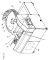
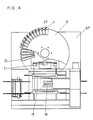
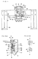
- Numeral 1 designates a tape feeding unit having both the function as a housing part 7 for a band shape part assembly 6 formed by fixing at equal intervals a plurality of electronic parts 3 having lead wires 2a and 2b coaxially extending therefrom with tapes 4 and 5 like paper, etc., which are readily curvable and the function for outfitting the part from the band shape assembly 6.
- Numeral 8 is a movable table for carrying a plurality of tape feeding units 1 and making a circular movement to move any one of arbitrary tape feeding units 1 to a specified part take-out position, which contains a driving part 9 for moving the movable table 8 to the set position and a chute 10 for guiding out the tapes 4 and 5 from which the parts are cut off and the discharged tapes are accumulated in a scrap box 12 after being cut to a specified length by a tape cutter 11 (to be described later).
- Numeral 13 is a cutter unit not only for separating from the tapes the lead wires of the part at the specified part take-out position, but for forming the lead wires into a specified shape and moving by turning to a printed substrate 14 in the state of these lead wires being passed along a guide groove, to be inserted thereinto.
- Numeral 15 is a substrate moving part for holding the set printed substrate 14 and setting the inserting position in the printed substrate 14 by moving fore and aft and right and left.
- Numeral 16 denotes a driving control part for controlling the mutually interlocked operations between the aforementioned tape feeding unit, movable table 8, tape cutter 11, driving motor 17 for the movable table 8, inserting head 18 as a working head which operates in concert with the cutter unit 13 and the substrate moving part 15, etc.
- the tape feeding unit 1 is described with reference to FIGS 3-10.
- parts of same type are put together with adhesive tapes 4 and 5 at equal intervals P.
- Numerals 19 and 19' denote feeding ratchet wheels for feeding out the band shape assembly 6 by a definite pitch, each of which has ratchets provided in agreement with the pitch P.
- the aforementioned ratchet wheels 19 and 19' are respectively fixed on the shaft 21 axially supported by the tape feeding unit body 20 at a dimension a little narrower than the taping width Wand on one end of the shaft 21, a driving ratchet wheel 22 having same number of ratchets as that of the ratchet wheels 19 and 19' is mounted.
- a lever 24 having mounted thereon a ratchet 23 which engages with the ratchet wheel 22 is swingably axially supported and on the opposite tip to the ratchet 23, a roller 25 for relieving frictional resistance when the lever 24 is pushed is provided.
- Numeral 26 designates a holding spring for the ratchet 23, and 27 a detent pawl for the ratchet wheel; thereby a timing for the ratchet wheels 19 and 19' and 22 is so adjusted that the taped parts are brought to the feeding line X - X' (a position where the part is cut by the cutter unit 13).
- Numeral 28 denotes a holding spring for detent pawl 27 for ratchet wheel.
- Numerals 29, 30 and 31 stand for staying plates for prevention of tapes' floating up; 32 and 32' are frames for holding therebetween parts housing box 33 which forms a parts housing space 7; both are fixed to the tape feeding unit body 20.
- This tape feeding unit 1 has fixing pins 34 and 35 at its base part; a plurality of tape feeding units 1 are engageable with coupling holes 36, 36'... provided at specified intervals in the movable table 8 and by means of a linked clamper 37 fixed to the movable table 8, the tape feeding unit body central part seat 20' is pressed and pivotally linked.
- the linked clamper 37 has a clamper body 38, pressure lever 40 provided with a pressure means 39, lever 41 and a handle lever 42; this handle lever 42 is coupled with the body through pins 43 and rotatably composed.
- the linked clamper 37 is located at a position corresponding to the central part seat 20' which is projecting from the movable table 8 in the direction at approximately a right angle to the unit body 20.
- the lever 24 is turned in the direction indicated by the arrow mark K; as one tooth of the ratchet wheel 22 is fed, the ratchet wheels 19 and 19' will feed the taped part 3 by the taping pitch P, making it possible to feed the parts one by one to the specified feed line X - X'.
- the pressure lever 40 is moved in the direction of the arrow mark Q, permitting the tape feeding unit 1 to flee from the movable table 8 by releasing the pressure.
- Numeral 44 designates a fixed cutting edge, and 45 a rotary cutting edge, both being cutting edges for cutting the tapes 4 and 5.
- concavities 44' and 45' On their surfaces along the line S - S', there are provided concavities 44' and 45' for discharging deposits produced after tapes have been cut.
- the fixed cutting edge 44 is held by a slider bracket 47 through a bracket 46, while the movable cutting edge 45 is mounted on sliders 48 which go up-down in concert along channels 47' and 47" formed in the slider bracket 47.
- Numeral 49 designates a guide block which is installed on the slider 48 to guide out tape scraps 4 and 5 which have been cut off.
- Numeral 50 is a lever which is adapted for up-down motion of the slider 48 and which is rotatably mounted on a fulcrum shaft 52 held by a slider bracket 47 through a spacer 51. It has a swinger 54 which is movable to right-left in the grooves 48' and 48" of the slider 48 and which is rotatably put on a pin 53, and it is coupled to a piston rod 55 through a block 56 and a pin 57.
- Numeral 58 denotes the body base of the tape cutter 11, which is engagingly holding the slider bracket 47, a bracket 61 on which stoppers 59 and 60 for regulating the stroke of the lever 50 are mounted, cylinder bracket 62, cylinder 63 and tape guide 64 and which is engagingly held by columns 65 and 66.
- This tape cutter 11 is located near the delivery port of the chute 10 installed inside the movable table 8 and is fixed to the body 67 through the columns on a line connecting the specified part- takeout position on the tape feeding unit 1 and the center of rotation of the movable table 8, without interfering with the chute 10 and the movable table 8.
- the scraps 4 and 5 flow down through the chute 10 and are fed to a position beyond the cutting position B - B'.
- the tape cutter 11 is set at the position indicated in FIGS. 11 and 12.
- a piston rod 55 moves in the arrow mark direction of FIG. 11 and the lever 50 turns upward with the fulcrum shaft 52 as the center.
- the slider 48 and the movable cutting edge 45 are raised; they are moving up by R.
- tape scraps 4 and 5 are cut off at the position on the line B - B' and discharged through a guide 64.
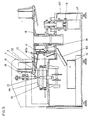
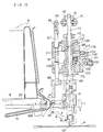
- Numeral 68 designates an insertion shaft, is axially supported for up-down sliding motion through guide cylinders 70 and 71, with its level adjustable by means of a nut 72.
- Numeral 73 denotes a driving shaft which is slidably axially supported in the inside hole of the insertion shaft 68 and which is coupled to a head lever 75 through rollers 74 and 74'.
- a pin 78 which is abutted on a retainer 77, pressed by a compression spring 76, is slidably inserted, with the spring pressure of the compression spring 76 so set that the rod 79 of the cutter unit 13 is pressured when inserting the part and that the pressuring deformation due to error of the diameter of the part 3 may be prevented (refer to FIG. 16).
- a head lever 75 is supported by a fulcrum shaft 80 at its one end and abutted on a cam 82' through a cam follower 82 under the downward pulling pressure by a pulling cylinder 81.
- Numeral 83 stands for a shaftfitted pinion for rotating the cutter unit 13.
- Numeral 84 denotes a slide rack meshed with the shaft-fitted pinion 83, which has a compression spring not shown in the drawings installed therein, which spring placed in a bracket 85, is always pushing upward the slide rack 84, thereby abutting it on the bottom surface 70' of the guide cylinder 70 through a roller 86.
- Numeral 87 designates a feed shaft for driving the lever 24 of the tape feeding unit 1, which is up-down slidably axially supported by the insertion head body 69.
- Numeral 88 denotes a feed block attached on the tip of the feed shaft 87, which abuts on a roller of the aforementioned lever 24 when feeding the tapes.
- Numeral 89 stands for a pin coupling the shaft 87 with the feed lever 90:
- Numeral. 91 designates a compression spring interposed between the insertion head body 69 and the shaft 87, which is always pressing the feed shaft 87 downward.
- FIG. 17 illustrates a layout of parts 3.
- 94 denotes a lever which subjected to the downward pulling pressure by the pulling cylinder 96, with the shaft 95 as the fulcrum, is abutted on a rotary plate cam 98 through a cam follower 97.
- the rod 99 is coupled to a plate 101 through a pin 100.
- a sliding body 102 is clamped by a plate 101, is internally in contact with guide plates 103 and 104 fixed on the insertion body 69, to be slidably held thereby and is slidably holding a slider 107 rotatably engaged on a pin 106 fixed on a lever 105.
- a guide 108 together with the lever 105, holds and slidably axially support the insertion shaft 68, mating its concavity 108' with a fitting part formed on the insertion shaft 68.
- the insertion shaft 68 is coupled to the driving shaft 73 at a ball shape concavity 73" through a steel ball 109 and axially supported by a guide cylinder 71 for free rotation and axial movement.
- the driving shaft 73 may be turned clockwise by 90° (arrow mark E line Y - Y') and it may be reset to the line Z - Z' by turning it anti-clockwise.
- a groove 71'for undoing the coupling between the insertion shaft 68 and the driving shaft 73, when inserting a part, is internally provided.
- FIG. 15 represents the origin point (start position) in the one cycle of the inserting operation, in which the cutter unit 13 is set by the turning of the movable table 8 to a position where it is free from collision with the tape feeding unit 1 in its specified position.
- the driving shaft 73 coupled to the head lever 75 is brought up and by the actions of the shaft-fitted pinion 83 and the slide rack 84 the cutter unit 13 is turned in the direction of the arrow Fto, be set on the line X - X'.
- the feed shaft 87 descends due to the turning of the cam 93 by which the operation of the feed lever 90 is set; then, the feed block 88 attached to the tip of the shaft pressures the lever 24 through the roller 25 of the tape feeding unit 1, thereby transferring to the line X - X' the electronic part assembly 6 which is placed one pitch (P) before the line X - X'. Then using a mechanism of the cutter unit 13, not shown in the drawings, the lead wires 2a and 2b of the electronic part assembly (FIG. 1) are cut and formed and held.
- the driving shaft 73 and the insertion shaft 68 begin to go down and the cutter unit 13 is given a turning (in the G direction) by the aforementioned shaft- fitted pinion 83 and the slide rack 84, to return to the origin.
- the driving shaft 73 and the insertion shaft 68 begin to go down (in the H direction); as a result, the insertion shaft 68 descends, until the nut 72 by which it is hung comes to abut on the guide cylinder 71.
- a guide 110 located on the cutter unit 13, corresponding to the inserting hole of the printed substrate 14 and holding the cut and formed lead wires 2a and 2b, is so positioned in level that it is brought on the top surface of the printed substrate 14.
- the steel ball 109 coupling the driving shaft 13 with the inserting shaft 68 moves to the groove 71' of the guide cylinder 71; then, only the driving shaft 73 descends and the pin 78 which is internally in contact with the stepped part 73' of the driving shaft 73 pressures a rod 79 placed in the cutter unit 13, thereby inserting the electronic part 3 into the insertion hole in the printed substrate.
- the driving shaft 73 starts rising (in the D direction), then to settle down to its former position at the origin. The aforementioned description gives the inserting operations in one cycle.
- the tapes 4 and 5 flowing down the chute 10 flow down the chute 10 successively and come to be discharged over the line B - B'. Then the tape cutter, as soon as the electronic part assembly 6 is transferred to the line X - X'. begins operating, to cut the tapes 4 and 5 which have crossed the line B - B'; their scraps are then accumulated in a waste box 12 after passing through a guide cylinder 111 and guide chute 112.
- the present invention is characterized in that the method of feeding to a fixed working head tapes on which electronic parts are sequentially assembled in the fitting order or the method of sequentially taking out and inserting parts held on tapes which have been fed to specified positions, using a turret type taking-out mechanism of working head, is not used, but in every cycle, the working head goes to specified positions to take out parts held on tapes which have been fed to these positions and at other different positions, their fitting work on a printed substrate is performed, so that the necessary parts may be randomly taken out by the working head and then, mounted on the printed substrate and further, by providing a pressure clamper for fixing the tape feeding unit which simplifies the attaching and detaching by unifying the tape feeding unit and the electronic part assembly and still further, by providing a tape cutter for cutting to a specified length the tape scraps which are left out after the parts have been cut off the electronic part assembly, parts replacement work is facilitated without permitting tape scraps to coil round the tape feeding unit.
Landscapes
- Engineering & Computer Science (AREA)
- Manufacturing & Machinery (AREA)
- Microelectronics & Electronic Packaging (AREA)
- Supply And Installment Of Electrical Components (AREA)
Abstract
Description
- The present invention relates to an electronic parts outfitting device for automatically mounting a variety of electronic parts on respectively specified positions on a printed substrate from a unit of such a device and provides such an outfitting device intended for enabling its efficient utilization in the phase of maintenance and workability.
- Heretofore available as devices for automatically making continuous mounting of different types of electronic parts such as resistor (FIG. 1a), diode (FIG. 1b), etc., were those which were roughly categorized into two types by the feeding method of the aforementioned electronic parts.
- Speaking of inserting devices, there is available as the first system a system in which, for example, an assembly of electronic parts in a band shape which are electronic parts different in type being arranged beforehand in the order of their insertion is prepared; such an assembly is directly fed to an insertion head, to make successive insertion of the parts (FIG. 2).
- On the other hand, as the second system, there is available a system in which assemblies of needed types each holding same type of electronic parts in a band shape are prepared; at the times of inserting respective electronic parts, such assemblies are selected in the order of insertion and the needed electronic part at a time is separated from each of the aforementioned assemblies and such parts are, then, conveyed to the insertion head for their insertion by such means as belt, pipe, etc. These methods have following disadvantages, respectively: .
- Thus in the first system, a plurality of types of parts need to be prepared as an assembly in a taping band shape; in such an assembly, their replacement can not be made, if insertion mistakes have occurred in any circumstances.
- On the other hand, in the second system, because of the use of a conveyor or pipe, its turning or tilting while conveying the parts interferes with their stable feeding to the insertion head. And because long time is taken for their transport, the number of their insertion cycles can not be increased. Moreover, outer walls of the conveyor and pipe tend to injure parts or deform lead wires.
- Against this background, there has already been proposed and put into practical use such an inserting device of a new type capable of solving such disadvantages of the aforementioned devices adapted for continuous insertion of different types of parts. This device employs such an arrangement as disclosed in USP 4205433 in which a means for holding side by side a plurality of taped assemblies each comprising electronic parts of same type and transferring one of the aforementioned plurality of electronic part assemblies to the specified position for feeding the part is provided and in which the insertion head makes a reciprocal motion between the aforementioned part feeding position and the position adjacent a printed substrate, located apart from the aforementioned position, to transfer the single electronic part which has been cut off the electronic part assembly at the aforementioned part feeding position to a position in proximity to the printed substrate and at this latter position, the electronic part is inserted into the aforementioned printed substrate. This system is called random access type, as against the sequential type of the aforementioned first system. The insertion device of this system has outstanding effects in response to insertion mistake of electronic part and stability in insertion.
- On the other hand, in the advancing process of automation by use of such outfitting device of electronic parts, needs not only for stabilization of arrangement but for dealing with the project of forming line with various types of automatic outfitting device are growing and there is a demand for development of outfitting devices which are to be designed for high work efficiency in totality through effective utilization of machine installing space and improvement in productivity.
- With regard to the device disclosed by the aforementioned USP 4205433, a plurality of electronic part assemblies are mounted on a movable stand in one direction and parallel to each other; the movable stand is moved along a straight line to bring a specified part to the neighborhood of the insertion head position, wherefore a large space is required in the length direction of the machine, raising the problem of the whole size of the machine becoming large. Besides a tape feeding unit is fixed to the movable table, causing trouble in displacement of parts and low workability; moreover, the tape scraps produced after the taped electronic parts have been inserted are discharged as they are; this poses the problem of such tape scraps coiling round the tape feeding unit, when it is attached or detached.
- In connection with the problem of space hereabove mentioned, a device for providing advantage is disclosed by. Japanese Patent Gazette No. 66466 of 1979. In this device, the electronic part assemblies are placed further outside the tape feeding unit which is located at the outer periphery of a movable stand in the shape of a circular table and an insertion head provided with a turret type insertion chuck mechanism effects sequential insertion of electronic parts.
- This device has such disadvantages as hereunder enumerated: First, a cartridge type arrangement is formed by unifying the tape feeding unit and the electronic part assemblies, but this requires time in their attaching and detaching. Secondly, for performing tape scrap disposal, tape cutting mechanisms are equipped in all tape feeding units mounted on the circular table, resulting in high manufacturing cost. And thirdly, in the event of whatever insertion is taking place, while the inserting device is in operation, the same parts can not be resupplied, because of the sequential insertion of electronic parts.
- The device of this invention has tape feeding units each for holding and intermittently transferring taped electronic part assembly having fixed at specified intervals a plurality of electronic parts, etc., provided with lead wires coaxially extending from both ends of each body, movable table being in disk shape and rotatably installed for transferring the aforementioned tape feeding unit removably held thereon to the specified first position, pressure clampers each removably installed on the aforementioned movable table in proximity and in correspondence to the tape feeding unit, working head for cutting the electronic part off the electronic part assembly at the aforementioned first position and then holding and transferring this electronic part to a second position located apart from the moving path of the aforementioned movable table but near the surface of a printed substrate, to mount this electronic part on the printed substrate, a chute for guiding to the neighborhood of the center of rotation of the aforementioned movable table tape scraps which have been left out after the electronic parts have been cut off the taped electronic assemblies, which is located beneath the bottom surface of the movable table in corre-. spondence with the aforementioned tape feeding unit, a tape cutter capable of cutting the aforementioned tape scraps, installed near the chute and between it and the center of rotation of- the movable table, where it is not interfered by this chute and the movable table; and has the effect of not being subjected to limitation in the direction of mounting the electronic parts on the printed substrate, in addition to the benefit of permitting random selection of electronic parts without making sequential arrangement of the electronic parts, and the effects of enabling easy unification and mounting and dismantling of the tape feeding unit and the electronic assembly and further, facile disposal of tape scraps by cutting them to a definite length, thereby permitting easy and quick execution of part change without suffering tape dangling.
-
- FIG. 1 (a) is a plan view of a resistor,
- FIG. 1 (b) a plan view of a diode and
- FIG. 1 (c) a plan view of a band shape part assembly used with the electronic part inserting device of an embodiment of this invention;
- FIG. 2 is a schematic diagram for explanation of a conventional part inserting device;
- FIG. 3 is a perspective view of an electronic part inserting device of an embodiment of this invention;
- FIG. 4 is a partly broken plan view of this electronic part inserting device;
- FIG. 5 is a side sectional view of the same;
- FIG. 6 is a partly broken sectional view of the tape feeding unit when inserting the electronic part;
- FIG. 7 is a side view of this tape feeding unit;
- FIG. 8 is a side sectional view of this tape feeding unit;
- FIG. 9 is a plan view of this tape feeding unit;
- FIG. 10 is a side view partly in section of this tape feeding unit installed on the movable table;
- FIG. 11 is an elevation of a tape cutter;
- FIG. 12 (a) is a sectional view along line A - A' shown in FIG. 11, and FIG. 12 (b) shows enlarged sectional views of the principal parts of fixed and removable cutting edges;
- FIG. 13 is a plan view partly in section of a working head;
- FIG. 14 is an elevation of the same;
- FIG. 15 is a side view partly in section of the same;
- FIG. 16 is an elevation partly in section of the principal part of the same; and
- FIG. 17 is a diagram for explanation of the arrangement of parts.
- The present invention will become more apparent from a description taken in connection with an embodiment of this invention and with reference to drawings following FIG. 3.
-
Numeral 1 designates a tape feeding unit having both the function as ahousing part 7 for a bandshape part assembly 6 formed by fixing at equal intervals a plurality ofelectronic parts 3 havinglead wires tapes band shape assembly 6.Numeral 8 is a movable table for carrying a plurality oftape feeding units 1 and making a circular movement to move any one of arbitrarytape feeding units 1 to a specified part take-out position, which contains adriving part 9 for moving the movable table 8 to the set position and achute 10 for guiding out thetapes scrap box 12 after being cut to a specified length by a tape cutter 11 (to be described later).Numeral 13 is a cutter unit not only for separating from the tapes the lead wires of the part at the specified part take-out position, but for forming the lead wires into a specified shape and moving by turning to a printedsubstrate 14 in the state of these lead wires being passed along a guide groove, to be inserted thereinto. Numeral 15 is a substrate moving part for holding the set printedsubstrate 14 and setting the inserting position in the printedsubstrate 14 by moving fore and aft and right and left. Numeral 16 denotes a driving control part for controlling the mutually interlocked operations between the aforementioned tape feeding unit, movable table 8, tape cutter 11, drivingmotor 17 for the movable table 8, insertinghead 18 as a working head which operates in concert with thecutter unit 13 and thesubstrate moving part 15, etc. - First, the
tape feeding unit 1 is described with reference to FIGS 3-10. In this embodiment as shown in FIG. 1c, parts of same type are put together withadhesive tapes intervals P. Numerals 19 and 19' denote feeding ratchet wheels for feeding out theband shape assembly 6 by a definite pitch, each of which has ratchets provided in agreement with the pitch P. Theaforementioned ratchet wheels 19 and 19' are respectively fixed on theshaft 21 axially supported by the tapefeeding unit body 20 at a dimension a little narrower than the taping width Wand on one end of theshaft 21, a drivingratchet wheel 22 having same number of ratchets as that of theratchet wheels 19 and 19' is mounted. On theshaft 21, alever 24 having mounted thereon aratchet 23 which engages with theratchet wheel 22 is swingably axially supported and on the opposite tip to theratchet 23, aroller 25 for relieving frictional resistance when thelever 24 is pushed is provided. Numeral 26 designates a holding spring for theratchet 23, and 27 a detent pawl for the ratchet wheel; thereby a timing for theratchet wheels detent pawl 27 for ratchet wheel. Numerals 29, 30 and 31 stand for staying plates for prevention of tapes' floating up; 32 and 32' are frames for holding therebetweenparts housing box 33 which forms aparts housing space 7; both are fixed to the tapefeeding unit body 20. Thistape feeding unit 1 has fixingpins tape feeding units 1 are engageable withcoupling holes 36, 36'... provided at specified intervals in the movable table 8 and by means of a linkedclamper 37 fixed to the movable table 8, the tape feeding unit body central part seat 20' is pressed and pivotally linked. - Then the linked
clamper 37 is described further in detail: The linkedclamper 37 has aclamper body 38,pressure lever 40 provided with a pressure means 39,lever 41 and ahandle lever 42; thishandle lever 42 is coupled with the body throughpins 43 and rotatably composed. The linkedclamper 37 is located at a position corresponding to the central part seat 20' which is projecting from the movable table 8 in the direction at approximately a right angle to theunit body 20. - By employing the structure as hereabove described, the
lever 24 is turned in the direction indicated by the arrow mark K; as one tooth of theratchet wheel 22 is fed, theratchet wheels 19 and 19' will feed the tapedpart 3 by the taping pitch P, making it possible to feed the parts one by one to the specified feed line X - X'. And by pulling up thehandle lever 42 of the linkedclamper 37 in the arrow direction M by a small muscle force, thepressure lever 40 is moved in the direction of the arrow mark Q, permitting thetape feeding unit 1 to flee from the movable table 8 by releasing the pressure. - In the following, the tape cutter 11 is described with reference to FIGS. 11, 12a and 12b.
Numeral 44 designates a fixed cutting edge, and 45 a rotary cutting edge, both being cutting edges for cutting thetapes cutting edge 44 is held by aslider bracket 47 through abracket 46, while themovable cutting edge 45 is mounted onsliders 48 which go up-down in concert alongchannels 47' and 47" formed in theslider bracket 47.Numeral 49 designates a guide block which is installed on theslider 48 to guide outtape scraps -
Numeral 50 is a lever which is adapted for up-down motion of theslider 48 and which is rotatably mounted on afulcrum shaft 52 held by aslider bracket 47 through aspacer 51. It has aswinger 54 which is movable to right-left in thegrooves 48' and 48" of theslider 48 and which is rotatably put on apin 53, and it is coupled to apiston rod 55 through ablock 56 and apin 57.Numeral 58 denotes the body base of the tape cutter 11, which is engagingly holding theslider bracket 47, abracket 61 on whichstoppers lever 50 are mounted,cylinder bracket 62,cylinder 63 andtape guide 64 and which is engagingly held bycolumns - This tape cutter 11 is located near the delivery port of the
chute 10 installed inside the movable table 8 and is fixed to thebody 67 through the columns on a line connecting the specified part- takeout position on thetape feeding unit 1 and the center of rotation of the movable table 8, without interfering with thechute 10 and the movable table 8. - The
scraps chute 10 and are fed to a position beyond the cutting position B - B'. At this time, the tape cutter 11 is set at the position indicated in FIGS. 11 and 12. As air is fed to acylinder 63 in this state through an air supply hose 63', apiston rod 55 moves in the arrow mark direction of FIG. 11 and thelever 50 turns upward with thefulcrum shaft 52 as the center. At the same time, theslider 48 and themovable cutting edge 45 are raised; they are moving up by R. Simultaneously, tape scraps 4 and 5 are cut off at the position on the line B - B' and discharged through aguide 64. - Then the former state is resumed by switching the air supply hose to 63". One cycle operation of the tape cutter 11 has now been described hereabove.
- Next, the
insertion head 18 is described with reference to FIGS. 13 through 17. -
Numeral 68 designates an insertion shaft, is axially supported for up-down sliding motion throughguide cylinders nut 72.Numeral 73 denotes a driving shaft which is slidably axially supported in the inside hole of theinsertion shaft 68 and which is coupled to ahead lever 75 throughrollers 74 and 74'. In the stepped part 73' of the drivingshaft 73, apin 78 which is abutted on aretainer 77, pressed by acompression spring 76, is slidably inserted, with the spring pressure of thecompression spring 76 so set that therod 79 of thecutter unit 13 is pressured when inserting the part and that the pressuring deformation due to error of the diameter of thepart 3 may be prevented (refer to FIG. 16). Ahead lever 75 is supported by afulcrum shaft 80 at its one end and abutted on a cam 82' through acam follower 82 under the downward pulling pressure by a pullingcylinder 81. Theinsertion shaft 68, although subjected to the downward pulling pressure transmitted from the head lever, is engaged by the stepped part 73' of thedrive shaft 73.Numeral 83 stands for a shaftfitted pinion for rotating thecutter unit 13.Numeral 84 denotes a slide rack meshed with the shaft-fittedpinion 83, which has a compression spring not shown in the drawings installed therein, which spring placed in abracket 85, is always pushing upward theslide rack 84, thereby abutting it on the bottom surface 70' of theguide cylinder 70 through aroller 86. -
Numeral 87 designates a feed shaft for driving thelever 24 of thetape feeding unit 1, which is up-down slidably axially supported by theinsertion head body 69.Numeral 88 denotes a feed block attached on the tip of thefeed shaft 87, which abuts on a roller of theaforementioned lever 24 when feeding the tapes.Numeral 89 stands for a pin coupling theshaft 87 with the feed lever 90: Numeral. 91 designates a compression spring interposed between theinsertion head body 69 and theshaft 87, which is always pressing thefeed shaft 87 downward. - The
feed lever 90 is supported by thefulcrum shaft 80 at its end and is abutting on acam 93 through a cam follower under the downward pulling pressure by the pulling cylinder not shown in the drawings. FIG. 17 illustrates a layout ofparts 3. When inserting apart 3 in the Y - Y' line direction which is on the same plane as the Z - Z' line, thepart 3 pinched by thecutter unit 13 along the Z - Z' line as previously described is changed to the Y - Y' line. - Referring to FIGS. 13, 14 and 15, 94 denotes a lever which subjected to the downward pulling pressure by the pulling
cylinder 96, with theshaft 95 as the fulcrum, is abutted on arotary plate cam 98 through acam follower 97. Therod 99 is coupled to aplate 101 through apin 100. - A sliding
body 102 is clamped by aplate 101, is internally in contact withguide plates insertion body 69, to be slidably held thereby and is slidably holding a slider 107 rotatably engaged on a pin 106 fixed on alever 105. Aguide 108, together with thelever 105, holds and slidably axially support theinsertion shaft 68, mating its concavity 108' with a fitting part formed on theinsertion shaft 68. Theinsertion shaft 68 is coupled to the drivingshaft 73 at aball shape concavity 73" through asteel ball 109 and axially supported by aguide cylinder 71 for free rotation and axial movement. With the aforementioned structure, by turning therotary plate cam 98, the drivingshaft 73 may be turned clockwise by 90° (arrow mark E line Y - Y') and it may be reset to the line Z - Z' by turning it anti-clockwise. On theguide cylinder 71, a groove 71'for undoing the coupling between theinsertion shaft 68 and the drivingshaft 73, when inserting a part, is internally provided. - In the following, the operations in inserting
electronic parts 3 are described with reference to FIGS. 5, 13, 14, 15 and 16: - FIG. 15 represents the origin point (start position) in the one cycle of the inserting operation, in which the
cutter unit 13 is set by the turning of the movable table 8 to a position where it is free from collision with thetape feeding unit 1 in its specified position. Under this state, by the turning of the cam 82' by which the operation of thehead lever 75 has been set beforehand, the drivingshaft 73 coupled to thehead lever 75 is brought up and by the actions of the shaft-fittedpinion 83 and theslide rack 84 thecutter unit 13 is turned in the direction of the arrow Fto, be set on the line X - X'. Simultaneously therewith, thefeed shaft 87 descends due to the turning of thecam 93 by which the operation of thefeed lever 90 is set; then, thefeed block 88 attached to the tip of the shaft pressures thelever 24 through theroller 25 of thetape feeding unit 1, thereby transferring to the line X - X' theelectronic part assembly 6 which is placed one pitch (P) before the line X - X'. Then using a mechanism of thecutter unit 13, not shown in the drawings, thelead wires shaft 73 and theinsertion shaft 68 begin to go down and thecutter unit 13 is given a turning (in the G direction) by the aforementioned shaft- fittedpinion 83 and theslide rack 84, to return to the origin. The drivingshaft 73 and theinsertion shaft 68 begin to go down (in the H direction); as a result, theinsertion shaft 68 descends, until thenut 72 by which it is hung comes to abut on theguide cylinder 71. Under this condition, aguide 110 located on thecutter unit 13, corresponding to the inserting hole of the printedsubstrate 14 and holding the cut and formedlead wires substrate 14. As the drivingshaft 73 further descends, thesteel ball 109 coupling the drivingshaft 13 with the insertingshaft 68 moves to the groove 71' of theguide cylinder 71; then, only the drivingshaft 73 descends and thepin 78 which is internally in contact with the stepped part 73' of the drivingshaft 73 pressures arod 79 placed in thecutter unit 13, thereby inserting theelectronic part 3 into the insertion hole in the printed substrate. After the insertion of the part has been finished, the drivingshaft 73 starts rising (in the D direction), then to settle down to its former position at the origin. The aforementioned description gives the inserting operations in one cycle. - As the
electronic part assembly 6 has passed the line X - X', thetapes chute 10 flow down thechute 10 successively and come to be discharged over the line B - B'. Then the tape cutter, as soon as theelectronic part assembly 6 is transferred to the line X - X'. begins operating, to cut thetapes waste box 12 after passing through a guide cylinder 111 and guidechute 112. - The present invention is characterized in that the method of feeding to a fixed working head tapes on which electronic parts are sequentially assembled in the fitting order or the method of sequentially taking out and inserting parts held on tapes which have been fed to specified positions, using a turret type taking-out mechanism of working head, is not used, but in every cycle, the working head goes to specified positions to take out parts held on tapes which have been fed to these positions and at other different positions, their fitting work on a printed substrate is performed, so that the necessary parts may be randomly taken out by the working head and then, mounted on the printed substrate and further, by providing a pressure clamper for fixing the tape feeding unit which simplifies the attaching and detaching by unifying the tape feeding unit and the electronic part assembly and still further, by providing a tape cutter for cutting to a specified length the tape scraps which are left out after the parts have been cut off the electronic part assembly, parts replacement work is facilitated without permitting tape scraps to coil round the tape feeding unit.
Claims (4)
Applications Claiming Priority (1)
| Application Number | Priority Date | Filing Date | Title |
|---|---|---|---|
| PCT/JP1983/000233 WO1985000724A1 (en) | 1983-07-20 | 1983-07-20 | Electronic part mounting apparatus |
Publications (3)
| Publication Number | Publication Date |
|---|---|
| EP0154652A1 EP0154652A1 (en) | 1985-09-18 |
| EP0154652A4 EP0154652A4 (en) | 1987-03-03 |
| EP0154652B1 true EP0154652B1 (en) | 1988-11-09 |
Family
ID=13790024
Family Applications (1)
| Application Number | Title | Priority Date | Filing Date |
|---|---|---|---|
| EP83902288A Expired EP0154652B1 (en) | 1983-07-20 | 1983-07-20 | Electronic part mounting apparatus |
Country Status (4)
| Country | Link |
|---|---|
| US (1) | US4631800A (en) |
| EP (1) | EP0154652B1 (en) |
| DE (1) | DE3378458D1 (en) |
| WO (1) | WO1985000724A1 (en) |
Families Citing this family (5)
| Publication number | Priority date | Publication date | Assignee | Title |
|---|---|---|---|---|
| GB8513296D0 (en) * | 1985-05-28 | 1985-07-03 | Dynapert Precima Ltd | Machines for handling electrical components |
| JPS62130596A (en) * | 1985-12-02 | 1987-06-12 | 三菱電機株式会社 | Electronic parts automatic assembly equipment |
| US4819699A (en) * | 1987-02-24 | 1989-04-11 | Alliance Automation Systems, Inc. | Cartridge feed system for automatic PCB loading machine |
| US5125307A (en) * | 1990-11-13 | 1992-06-30 | Emhart Inc. | Cropping mechanism for surface mount placement machine |
| KR100213874B1 (en) * | 1996-07-29 | 1999-08-02 | 윤종용 | Electronic component tape and system for using the said tape |
Family Cites Families (11)
| Publication number | Priority date | Publication date | Assignee | Title |
|---|---|---|---|---|
| US3521347A (en) * | 1967-12-26 | 1970-07-21 | Gulf & Western Ind Prod Co | Apparatus for removing and disposing of wrapping bands |
| US3777350A (en) * | 1971-07-26 | 1973-12-11 | Matsushita Electric Industrial Co Ltd | Component mounting apparatus |
| JPS6018160B2 (en) * | 1977-01-12 | 1985-05-09 | 松下電器産業株式会社 | Electrical parts insertion device |
| JPS6059759B2 (en) * | 1977-06-10 | 1985-12-26 | 遠州製作株式会社 | Feeding device in electrical parts insertion machine |
| JPS54126962A (en) * | 1978-03-24 | 1979-10-02 | Fuji Machine Mfg | Method of and apparatus for inserting electronic components into printed board |
| JPS54144974A (en) * | 1978-05-02 | 1979-11-12 | Tdk Electronics Co Ltd | Automatic electronic component insertion apparatus |
| US4263708A (en) * | 1978-06-03 | 1981-04-28 | Tokyo Denki Kagaku Kogyo Kabushiki Kaisha | Machine for automatically inserting parallel lead electronic components into a printed circuit board |
| JPS5522834A (en) * | 1978-08-03 | 1980-02-18 | Matsushita Electric Industrial Co Ltd | Device for arraying parts |
| US4403390A (en) * | 1978-10-31 | 1983-09-13 | Usm Corporation | Radial lead inserting machine |
| US4245385A (en) * | 1979-07-09 | 1981-01-20 | Universal Instruments Corporation | Radial lead component insertion machine |
| US4527324A (en) * | 1981-05-06 | 1985-07-09 | Universal Instruments Corporation | Leadless chip placement machine for printed circuit boards |
-
1983
- 1983-07-20 US US06/717,274 patent/US4631800A/en not_active Expired - Lifetime
- 1983-07-20 EP EP83902288A patent/EP0154652B1/en not_active Expired
- 1983-07-20 WO PCT/JP1983/000233 patent/WO1985000724A1/en not_active Ceased
- 1983-07-20 DE DE8383902288T patent/DE3378458D1/en not_active Expired
Also Published As
| Publication number | Publication date |
|---|---|
| US4631800A (en) | 1986-12-30 |
| DE3378458D1 (en) | 1988-12-15 |
| EP0154652A1 (en) | 1985-09-18 |
| EP0154652A4 (en) | 1987-03-03 |
| WO1985000724A1 (en) | 1985-02-14 |
Similar Documents
| Publication | Publication Date | Title |
|---|---|---|
| EP0080512B1 (en) | Apparatus for mounting electrical part | |
| US4658494A (en) | Apparatus for drilling printed circuit boards | |
| US4205433A (en) | Electric part insertion method and apparatus | |
| US3593404A (en) | Multisize dual center distance electronic component insertion machine | |
| WO2013042544A1 (en) | Electronic circuit component mounter | |
| US4742612A (en) | Method of manufacturing wire harness by using nipped connector and apparatus therefor | |
| US7150084B2 (en) | Slide fastener manufacturing apparatus | |
| EP0154652B1 (en) | Electronic part mounting apparatus | |
| EP0119599B1 (en) | Forming apparatus for performing bending operations | |
| US3796363A (en) | Multiple component insertion apparatus | |
| EP0195086B1 (en) | Automatic electronic part-inserting apparatus | |
| JP3174115B2 (en) | Cassette exchange device for progressive processing equipment | |
| GB2091138A (en) | Automatic assembling machine | |
| US6224124B1 (en) | Parts transfer and control circuit system | |
| US4370804A (en) | Electronic component inserting apparatus | |
| JPH029597Y2 (en) | ||
| USRE27968E (en) | Multisize variable center electronic component insertion machine | |
| JPH038599B2 (en) | ||
| EP0118629A2 (en) | Electronic component insertion apparatus | |
| JPH025038B2 (en) | ||
| JP6482623B2 (en) | Electronic circuit component mounting machine | |
| JPS6351817B2 (en) | ||
| CN214236823U (en) | Guide groove guide mechanism | |
| CN220030091U (en) | Quick workpiece penetrating machine | |
| CN214236822U (en) | Spacer support adjusting mechanism |
Legal Events
| Date | Code | Title | Description |
|---|---|---|---|
| PUAI | Public reference made under article 153(3) epc to a published international application that has entered the european phase |
Free format text: ORIGINAL CODE: 0009012 |
|
| 17P | Request for examination filed |
Effective date: 19850318 |
|
| AK | Designated contracting states |
Kind code of ref document: A1 Designated state(s): DE FR GB Designated state(s): DE FR GB |
|
| A4 | Supplementary search report drawn up and despatched |
Effective date: 19870303 |
|
| 17Q | First examination report despatched |
Effective date: 19871215 |
|
| GRAA | (expected) grant |
Free format text: ORIGINAL CODE: 0009210 |
|
| AK | Designated contracting states |
Kind code of ref document: B1 Designated state(s): DE FR GB |
|
| REF | Corresponds to: |
Ref document number: 3378458 Country of ref document: DE Date of ref document: 19881215 |
|
| ET | Fr: translation filed | ||
| PLBE | No opposition filed within time limit |
Free format text: ORIGINAL CODE: 0009261 |
|
| STAA | Information on the status of an ep patent application or granted ep patent |
Free format text: STATUS: NO OPPOSITION FILED WITHIN TIME LIMIT |
|
| 26N | No opposition filed | ||
| REG | Reference to a national code |
Ref country code: GB Ref legal event code: 746 Effective date: 19970901 |
|
| PGFP | Annual fee paid to national office [announced via postgrant information from national office to epo] |
Ref country code: FR Payment date: 19990709 Year of fee payment: 17 |
|
| PGFP | Annual fee paid to national office [announced via postgrant information from national office to epo] |
Ref country code: GB Payment date: 19990714 Year of fee payment: 17 |
|
| PGFP | Annual fee paid to national office [announced via postgrant information from national office to epo] |
Ref country code: DE Payment date: 19990723 Year of fee payment: 17 |
|
| PG25 | Lapsed in a contracting state [announced via postgrant information from national office to epo] |
Ref country code: GB Free format text: LAPSE BECAUSE OF NON-PAYMENT OF DUE FEES Effective date: 20000720 |
|
| GBPC | Gb: european patent ceased through non-payment of renewal fee |
Effective date: 20000720 |
|
| PG25 | Lapsed in a contracting state [announced via postgrant information from national office to epo] |
Ref country code: FR Free format text: LAPSE BECAUSE OF NON-PAYMENT OF DUE FEES Effective date: 20010330 |
|
| REG | Reference to a national code |
Ref country code: FR Ref legal event code: ST |
|
| PG25 | Lapsed in a contracting state [announced via postgrant information from national office to epo] |
Ref country code: DE Free format text: LAPSE BECAUSE OF NON-PAYMENT OF DUE FEES Effective date: 20010501 |