EP0154502B1 - Pasteurizable container closure - Google Patents
Pasteurizable container closure Download PDFInfo
- Publication number
- EP0154502B1 EP0154502B1 EP85301317A EP85301317A EP0154502B1 EP 0154502 B1 EP0154502 B1 EP 0154502B1 EP 85301317 A EP85301317 A EP 85301317A EP 85301317 A EP85301317 A EP 85301317A EP 0154502 B1 EP0154502 B1 EP 0154502B1
- Authority
- EP
- European Patent Office
- Prior art keywords
- skirt
- container
- neck
- mouth
- cap
- Prior art date
- Legal status (The legal status is an assumption and is not a legal conclusion. Google has not performed a legal analysis and makes no representation as to the accuracy of the status listed.)
- Expired - Lifetime
Links
Images
Classifications
-
- B—PERFORMING OPERATIONS; TRANSPORTING
- B67—OPENING, CLOSING OR CLEANING BOTTLES, JARS OR SIMILAR CONTAINERS; LIQUID HANDLING
- B67B—APPLYING CLOSURE MEMBERS TO BOTTLES JARS, OR SIMILAR CONTAINERS; OPENING CLOSED CONTAINERS
- B67B3/00—Closing bottles, jars or similar containers by applying caps
- B67B3/02—Closing bottles, jars or similar containers by applying caps by applying flanged caps, e.g. crown caps, and securing by deformation of flanges
- B67B3/10—Capping heads for securing caps
- B67B3/18—Capping heads for securing caps characterised by being rotatable, e.g. for forming screw threads in situ
-
- B—PERFORMING OPERATIONS; TRANSPORTING
- B65—CONVEYING; PACKING; STORING; HANDLING THIN OR FILAMENTARY MATERIAL
- B65D—CONTAINERS FOR STORAGE OR TRANSPORT OF ARTICLES OR MATERIALS, e.g. BAGS, BARRELS, BOTTLES, BOXES, CANS, CARTONS, CRATES, DRUMS, JARS, TANKS, HOPPERS, FORWARDING CONTAINERS; ACCESSORIES, CLOSURES, OR FITTINGS THEREFOR; PACKAGING ELEMENTS; PACKAGES
- B65D41/00—Caps, e.g. crown caps or crown seals, i.e. members having parts arranged for engagement with the external periphery of a neck or wall defining a pouring opening or discharge aperture; Protective cap-like covers for closure members, e.g. decorative covers of metal foil or paper
- B65D41/32—Caps or cap-like covers with lines of weakness, tearing-strips, tags, or like opening or removal devices, e.g. to facilitate formation of pouring openings
- B65D41/34—Threaded or like caps or cap-like covers provided with tamper elements formed in, or attached to, the closure skirt
- B65D41/348—Threaded or like caps or cap-like covers provided with tamper elements formed in, or attached to, the closure skirt the tamper element being rolled or pressed to conform to the shape of the container, e.g. metallic closures
Definitions
- Pasteurized bottled beer is produced by filling cold beer into previously rinsed containers which are then capped. The bottled beer is then passed through a pasteurizer where the bottle is subjected to an external spray of water for 20 minutes or more with the temperature of the water being approximately 65.5°C (150 degrees F). The pasteurizer is programmed such that the beer temperature rises to about 60°C (140 degrees F) and is held at that temperature for about 6 minutes. The product is then cooled as it exits the pasteurizer.
- closures have been employed in an attempt to seal the containers in such a manner that when subjected to the elevated temperature of pasteurization and inherent internal pressures, the integrity of the seal remains intact.
- One type of closure employed was the conventional aluminum roll-on closure of the type used on soft drink bottles wherein the skirt of the closure has threads or impressions formed in it by the deformation of the skirt against the finish of the container.
- An example of an apparatus for applying such beverage closures with a locking band (pilfer proof ring) is described in United States Patent 3,760,561. Closures of molded plastic similar to those disclosed in United States Patents 4,322,009 or 4,352,436 have also been tested. It has been observed that when PET containers are sealed with conventional aluminum roll-on caps or with plastic caps featuring a top edge seal, and the sealed containers then subjected to the pasteurization process, closure leak failures occur in more than 5% of the containers.
- the cause for the failure is generally a reforming or a movement of the sealing surface, primarily of the bottle finish, under the temperatures and pressures involved during the pasteurization process.
- the polyester forming the container itself be modified by a heat treatment. See, for example, United States Patents 4,039,641 and 4,375,442.
- the elevated temperatures and pressures of the pasteurization treatment cause the thermoplastic in the region of the finish to creep sufficiently to cause seal failure resulting in loss of carbonation and possible product contamination.
- Cited British Patent Specification No 16,645 of 1913 is concerned with the fitting of a closure cap to a glass bottle.
- a closure member formed from a thin metal element having a pre-threaded tubular skirt closed at one end by an end wall.
- the bottle neck is provided with a peripheral flange spaced from the top of the neck and against which the free end of the skirt bears when the element is initially screwed into place with a compressible disc interposed between the bottle top and the inside of the cap.
- the cap and the bottle neck are then placed in a press which presses firmly upon the cap end wall so that the latter is effectively sandwiched between the press and the ledge on the bottle neck.
- the sealing operation of the press very slightly indents the top of the cap such that the cap end wall presses firmly against the compressible disc to cause the latter to seal against the bottle neck free end.
- the cap skirt free end presses against the outwardly directed ledge on the bottle neck and as a result material of the skirt is upset to produce a circumferential rim which takes up surplus material of the skirt and in so doing ensures that the cap end remains level with the top of the bottle.
- plastics materials as containers has resulted in considerable problems in maintaining the integrity of a closure seal when the container is subjected to the temperature and pressure regimes such as those involved in current pasteurisation processes and that many attempts have been made to achieve the desirable reliable seal between a swageable metal closure cap and the neck of a container formed from a plastics material.
- the reformation of conventional aluminum roll-on caps or other caps can be achieved at the time of application by the use of a suitable pressure block to form a closure.
- the pressure block includes a central land of a diameter slightly less than the inner diameter of the mouth of the container to which the closure is to be applied.
- the central land has an axial dimension sufficient to displace a central portion in the form of a disc or cylinder of the material forming the cap into the mouth of the container so as to enable the container to resist radial deformation.
- the skirt of the aluminum cap can be elongated slightly so as to still properly interact with the conventionally positioned pilfer-proof enlargement band on the bottle.
- a conventionally sized aluminum roll-on cap can be used with a bottle having a slightly narrower pilfer proof band.
- a bottle 10 is shown in Fig. 1 which has been formed by conventional blow molding techniques of a suitable plastic material, such as polyethylene terephthalate, polypropylene, polyethylene, or polyvinylchloride.
- the bottle 10 has an opening 12 at the top which includes a top sealing surface 14 and a screw-threaded finish 16 terminating in its lower end with a pilfer-proof band 18.
- a neck support ledge 20 Spaced below the pilfer proof band 18 is a neck support ledge 20.
- Below the neck support ledge 20 is a tubular sidewall or body portion 22.
- the bottle 10 typically terminates at its lower end in a generally convex or dome-shaped pressure bottom 24 which is enclosed in a base cup 26 either cemented or snap fit to the lower end of the bottle 10.
- the bottle 10 is generally symmetrical about longitudinal axis 28 although various designs have been adopted particularly for the tubular sidewall portion 22 as a secondary indication of the bottle contents.
- Bottles 10 having the general configuration illustrated in Fig. 1 have been subjected to a crystallization of the finish 16 in general accordance with the teachings of United States Patent 4,375,442.
- a sectional detail of such a bottle 10 is shown in both Figs. 2 and 3.
- the crystallized section 11 shows some small variation of the linearity of the internal surface 13 of the bottle 10 due principally to heat shrinkage which occurs during the crystallization process.
- the uncrystallized portion 15 of bottle 10 remains substantially undeformed even through a typical capping procedure.
- an aluminum cap 30 which includes a deformable plastic liner typically made of a moldable thermoplastic such as polyvinylchloride or ethylenevinylacetate.
- the cap 30 includes a flat top wall 32 and a skirt portion 34 which has been swaged by rollers against the finish 16 of the bottle 10 in order to form cooperative threads 36.
- the process for forming such threads is well known and disclosed, for example, in United States Patent 3,760,561.
- the cap 30 also includes a pilfer-proof ring portion 38 which has been swaged under the pilfer-proof band 18 at the time the threads 36 are formed.
- a cap 30 When a cap 30 is properly applied as shown in Fig. 2 under the usual soft drink bottling process which includes no pasteurization or other elevated temperature scheme, the cap seals satisfactorily and a negligible failure rate is observed.
- a cap When such a cap is employed in bottling beer or other commodities which are then subjected to a post bottling pasteurization process as previously outlined, it has been observed that the neck portion of the bottle 10 has deformed to the shape shown in Fig. 3. Despite the fact that portion 11 of the bottle has been crystallized or heat set, considerable deformation particularly of the sealing surface 14 is observed. Tests have shown that a failure rate of more than 5% can be expected even in bottles having crystallized finishes containing beer after having completed the beer pasteurization cycle described above.
- the deformation observed is characterized by an essentially radial inward collapse of the mouth portion 12 which in turn causes the sealing surface 14 to draw away from the rim portion 33 of the cap 30. While in many instances the deformation of the bottle is so small as to not cause a problem, in more that 5% of the bottles, the deformation is sufficient to cause a leak to develop.
- cap 40 constructed in accordance with the present invention.
- One such cap 40 is shown in Fig. 4 to include a closed end and an annular skirt portion 42 having threads 44 engaging the external screw threaded finish 16 of the container 10.
- the closed end includes a rim portion 46 integral with the top 45 of the skirt portion 42 which extends radially inward from the skirt and sealingly engages the sealing surface 14 of the bottle and an internal support portion 48.
- This support portion 48 is integral with the inner edge 47 of the rim portion 46 and depends therefrom into the mouth 12 of the container.
- the support portion 48 has the form of a cylinder closed at its lower end and whose cylindrical wall defines a second skirt 47A extending axially internally of the container neck, and whose closed lower end defines a radially extending end wall 48A.
- the combination of the lower end of the second skirt and the peripheral region of the end wall 48A produces a circumferential region of sufficient compressive strength to resist any radial collapse of the top edge of the mouth or opening of the bottle so as to maintain the integrity of contact between the rim portion 46 of the cap and the sealing surface 14 of the container 10.
- the cap will preferably include a pilfer-proof ring 49 which engages the pilfer-proof band 18 of the container in the usual fashion.
- the cap 40 will include a conventional liner 41 similar to the liner 32 of cap 30.
- Cap 50 is shown to be constructed of a suitable moulded plastic resin such as polypropylene, polyethylene, copolymers or mechanical blends of these, or other suitable polymers.
- the cap 50 can include one or more sealing rings or ridges such as are variously disclosed in United States Patents 4,276,989, 4,299,328, and 4,398,645.
- the cap can include a flowed-in sealing liner 52 such as that disclosed in United States Patent No. 4,331,249 the material of which may be selected from a vinylchloride type resin and can include any of those disclosed by United States Patent No. 4,392,581.
- the cap 50 includes a skirt portion 54 having threads 55 engaging the external screw-threaded finish 16 of the container 10.
- the rim portion 56 including either the liner 52 as illustrated or sealing rings as disclosed in prior art, engages the sealing surface 14 of the bottle 10.
- An internal support portion 58 depends from the rim portion 56 into the mouth 12 of the container 10.
- the material selected for forming the support portion should have sufficient compressive strength to resist any radial inward collapse of the top edge 12 of the bottle 10 so as to maintain the integrity of contact between the rim portion 56 of the cap 50 and the sealing surface 14 of the container 10.
- the cap 50 can include a pilfer-proof ring 59 which engages the pilfer-proof band 18 of the bottle 10.
- the cap 50 can be applied with the aid of apparatus such as that disclosed in United States Patent 4,308,707.
- the cap shown in Fig. 4 was installed in a manner discussed below on PET bottles containing beer.
- the bottles did not have a heat treated or crystallized finish but instead were made of conventional amorphous untreated PET.
- the bottles with the cap 40 installed in place were subjected to the convention beer pasteurization treatment discussed above and no failures whatsoever were observed. It is believed that the central support portion 48 of cap 40 provided a sufficient resistance to counter any tendency for the radial collapse of the top portion of the bottle during the pasteurization procedure thereby maintaining the integrity of contact between the top sealing surface 14 of the bottle and the rim portion 46 of the cap.
- the central land portion 64 comprises one end of a cylinder 67 having three distinct radius portions including the land portion 64 and outer rim portion 66 and a body portion 68.
- the outer rim portion 66 and body portion 68 are snugly received within the sleeve 63 of the pressure block 60 while the central land portion 64 extends axially downward so as to project into the container mouth 12.
- Figs. 6-8 The method for simultaneously forming and applying a closure in accordance with the present invention is illustrated in Figs. 6-8.
- a conventional aluminum roll-on cap blank 43 is positioned over the finish 14 of the bottle 10 and the capping machine with the modified pressure block 60 descends to contact the top of the cap blank 43.
- the bottle 10 is retained and supported by the neck support 20 so that a compressive force may be applied to the cap blank 43.
- the central land portion 64 of the pressure block 60 contacts and depresses a central portion in the form of cylinder or disk 48 into the mouth 12 of the bottle as shown in Fig. 7. This causes the contiguous annular portion 47 into conforming relation with the cylindrical inner surface 12 of the rim of the bottle 10.
- the annular ring portion 62 on the lower end of sleeve 63 of the pressure block 60 then contacts the outer rim 45 to pinch the liner 41 in tight sealing relation with the sealing surface 14 of the bottle 10.
Landscapes
- Engineering & Computer Science (AREA)
- Mechanical Engineering (AREA)
- Closures For Containers (AREA)
- Containers And Packaging Bodies Having A Special Means To Remove Contents (AREA)
- Dental Preparations (AREA)
Abstract
Description
- This invention relates generally to closures for containers formed of thermoplastic resins, and particularly to closures which are specifically designed for sealing such containers of pressurized liquids, such as carbonated beverages in situations where, after filling, the bottle and its contents will be subjected to an elevated heat treatment of one sort or another, such as pasteurization.
- The use of thermoplastic resins to form bottles for containing various liquid commodities has expanded rapidly in recent years. Much of the growth has occurred in the development of non- returnable containers for carbonated beverages, the containers being typically molded of thermoplastic polyethylene terephthalate (PET). Bottles of this construction are disclosed in United States Patent 3,733,309. The toiletry, cosmetic, detergent, and pharmaceutical markets are examples of other industries in which significant growth has occurred in the use of such plastic containers and bottles. Despite this expansion, the development of satisfactory closures for such bottles for certain products has remained illusive.
- Certain products require post-bottling heat treatment, such as pasteurization, to assure stable product quality and long shelf life. An example of such a product is beer. Pasteurized bottled beer is produced by filling cold beer into previously rinsed containers which are then capped. The bottled beer is then passed through a pasteurizer where the bottle is subjected to an external spray of water for 20 minutes or more with the temperature of the water being approximately 65.5°C (150 degrees F). The pasteurizer is programmed such that the beer temperature rises to about 60°C (140 degrees F) and is held at that temperature for about 6 minutes. The product is then cooled as it exits the pasteurizer.
- Numerous closures have been employed in an attempt to seal the containers in such a manner that when subjected to the elevated temperature of pasteurization and inherent internal pressures, the integrity of the seal remains intact. One type of closure employed was the conventional aluminum roll-on closure of the type used on soft drink bottles wherein the skirt of the closure has threads or impressions formed in it by the deformation of the skirt against the finish of the container. An example of an apparatus for applying such beverage closures with a locking band (pilfer proof ring) is described in United States Patent 3,760,561. Closures of molded plastic similar to those disclosed in United States Patents 4,322,009 or 4,352,436 have also been tested. It has been observed that when PET containers are sealed with conventional aluminum roll-on caps or with plastic caps featuring a top edge seal, and the sealed containers then subjected to the pasteurization process, closure leak failures occur in more than 5% of the containers.
- It has been observed that the cause for the failure is generally a reforming or a movement of the sealing surface, primarily of the bottle finish, under the temperatures and pressures involved during the pasteurization process. To overcome this problem, it has been suggested that the polyester forming the container itself be modified by a heat treatment. See, for example, United States Patents 4,039,641 and 4,375,442. However, even when the bottles are heat-set and conventional closures as previously discussed are employed, the elevated temperatures and pressures of the pasteurization treatment cause the thermoplastic in the region of the finish to creep sufficiently to cause seal failure resulting in loss of carbonation and possible product contamination.
- It has been suggested to provide a separate hermetic seal over the mouth of the bottle, for example, by a mylar film sonically welded to the mouth of the bottle. The presence of the welded seal is not only permitted but also desirable in certain industries, such as pharmaceuticals in that it can be used to indicate to the purchaser the absence of any tampering with the contents of the container. In other industries, however, the presence of such a seal is thought to be commercially unacceptable to the public. It is generally accepted that the presence of such a sonically welded seal on the mouth of a bottle containing beer, ale, or other malt liquor would be commercially unsatisfactory.
- Cited British Patent Specification No 16,645 of 1913 (Reference D1) is concerned with the fitting of a closure cap to a glass bottle. In this particular Reference there is disclosed the idea of capping a glass bottle by a closure member formed from a thin metal element having a pre-threaded tubular skirt closed at one end by an end wall. The bottle neck is provided with a peripheral flange spaced from the top of the neck and against which the free end of the skirt bears when the element is initially screwed into place with a compressible disc interposed between the bottle top and the inside of the cap. The cap and the bottle neck are then placed in a press which presses firmly upon the cap end wall so that the latter is effectively sandwiched between the press and the ledge on the bottle neck. The sealing operation of the press very slightly indents the top of the cap such that the cap end wall presses firmly against the compressible disc to cause the latter to seal against the bottle neck free end. However, before this actual sealing stage is reached the cap skirt free end presses against the outwardly directed ledge on the bottle neck and as a result material of the skirt is upset to produce a circumferential rim which takes up surplus material of the skirt and in so doing ensures that the cap end remains level with the top of the bottle.
- It is also known to provide closure cap devices made from moulded plastics materials which each include an end wall and a threaded skirt formation in which the end wall includes a central internal protrusion and an annular rim forming channel located intermediate of the protrusion and the skirt. The protrusion forms a thicker central core coaxially positioned with respect to the threaded skirt which latter is intended to screw onto complementary threads provided upon the container neck. The French specification No 1050765 can conveniently be regarded as being representative of this type of closure.
- It is very highly desirable that the well known swageble metal closure cap which is fitted to a container by a pressing and/or swaging operation should be satisfactorily usable in conjunction with plastics bottles even though plastics material regarded as being suitable for the production of bottles presents physical characteristics which tend to reduce their resistance to distortive forces and pressures.
- The use of plastics materials as containers has resulted in considerable problems in maintaining the integrity of a closure seal when the container is subjected to the temperature and pressure regimes such as those involved in current pasteurisation processes and that many attempts have been made to achieve the desirable reliable seal between a swageable metal closure cap and the neck of a container formed from a plastics material.
- A combination of the teachings of the two above mentioned specifications provides no information whatsoever at solving the problems with which the present application is concerned namely overcoming the distortability of a plastics container under certain relatively adverse conditions and still be able to use as a closure for a plastics container a metallic tubular blank closed at one end and which is sealingly fitted by deforming the material of the blank to provide the closure structure.
- According to a first aspect of the invention there is provided a method of sealing a container having a hollow body capable of containing a liquid under elevated pressure, a region including a neck having an externally threaded finish on at least a portion thereof, and an opening defining a mouth formed by an annular top surface co-axial with the axis of the neck, the method including the steps of:
- providing a cap blank of metallic sheet material of a uniform wall thickness and having a tubular skirt and a closed end;
- situating the cap blank over the open mouth of the container;
- deforming the tubular skirt of the cap blank so as to engage the threaded finish, the engagement causing a fluid tight seal between the neck mouth and the cap blank; and
- depressing at least the central region of the closed end of the blank towards the interior of the neck, such a method being known from GB-A-16645 characterised by the steps of:
- using a container of plastics material;
- producing from a first portion of the cap blank closed end, as a result of the depressing step, a cylindrical second skirt extending axially internally of the neck with the upper end of the second skirt connecting with the first skirt through a rim portion overlying the neck mouth;
- producing from a second portion of the cap blank closed end, as a result of the depressing step, a radially extending end wall bridging the interior of the lower end of the second skirt, and
- providing from the combination of the lower end of the second skirt and a peripheral region of the end wall a circumferential region having sufficient mechanical strength to resist radial deformation of thetop region of the mouth of the container neck in the event of radially directed forces being applied to or produced in the material of the plastics container neck mouth, thereby maintaining the fluid tight seal between the neck mouth and the rim portion.
- According to a further aspect of the invention there is provided the combination of a container and closure member, the container including a hollow body containing a liquid under elevated pressure; a region including a neck having an externally threaded finish on at least a portion thereof, and a mouth defined by an annular top opening co-axial with the axis of the neck, the closure member being formed from a cap blank of metallic sheet of uniform wall thickness and having a tubular skirt, the tubular skirt having a screw threaded region complementary to the threaded finish of the container and co-operatively engaging the threaded finish, and a closed end including a radially inwardly directed rim portion whose outer periphery is integral with the tubular skirt and a depressed central portion integrally connected with the inner periphery of the rim portion (such a combination being known from GB-A-16645), characterised in that the container is formed of a plastics material and in that the depressed central portion comprises a cylindrical second skirt integrally connected with and depending from the inner periphery of the rim portion into the neck of the container, and an end wall integrally extending radially inward from a lower end of the second skirt below the top region of the mouth to produce a circumferential region having sufficient mechanical strength to resist radial deformation of the top region of the mouth of the container neck in the event of radially directed forces being applied to or produced in the material of the container neck mouth, thereby maintaining the fluid tight seal between the neck mouth and the rim portion.
- The reformation of conventional aluminum roll-on caps or other caps can be achieved at the time of application by the use of a suitable pressure block to form a closure. The pressure block includes a central land of a diameter slightly less than the inner diameter of the mouth of the container to which the closure is to be applied. The central land has an axial dimension sufficient to displace a central portion in the form of a disc or cylinder of the material forming the cap into the mouth of the container so as to enable the container to resist radial deformation. The skirt of the aluminum cap can be elongated slightly so as to still properly interact with the conventionally positioned pilfer-proof enlargement band on the bottle. Alternatively, a conventionally sized aluminum roll-on cap can be used with a bottle having a slightly narrower pilfer proof band.
- Early experimental results suggest that the present invention is adaptable to all conventional finish sizes including both 28mm and 38mm. Surprisingly, it has been determined that it is no longer necessary to use bottles with heat-set finishes and instead conventional amorphous untreated bottle finishes of PET or other thermoplastic resin can be employed with the present cap with no seal failure occurring during or subsequent to the conventional beer pasteurization process.
- The various features and advantages derived from the present invention can be more readily understood by a consideration of the following discussion and the accompanying drawings illustrating the prior art and the invention, and showing a preferred embodiment of the invention exemplifying the best mode of carrying out the invention as presently perceived. In such drawings:
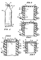
- Fig. 1 is an elevation view of a typical PET bottle on which a cap of the present invention can be employed.
- Fig. 2 is a sectional detail view of a conventional PET bottle having a heat-set finish with a conventional roll-on aluminum cap properly positioned thereon.
- Fig. 3 is a sectional view of the bottle and cap shown in Fig. 2 subsequent to the beer pasteurization treatment.
- Fig. 4 is a sectional view of an aluminum roll-on cap in accordance with the present invention.
- Fig. 5 is a sectional view of a molded plastic cap in accordance with the present invention.
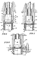
- Fig. 6 is a partial sectional view of a pressure block in accordance with the present invention in touching contact with a cap blank on the top of a bottle.
- Fig. 7 is a sectional view of the pressure block shown in Fig. 6 in full pressure contact forming the cap blank on the top of the bottle.
- Fig. 8 is a sectional view of the pressure block shown in Fig. 6 with the thread forming members engaging the skirt of the cap to roll or swage the closure threads.
- A
bottle 10 is shown in Fig. 1 which has been formed by conventional blow molding techniques of a suitable plastic material, such as polyethylene terephthalate, polypropylene, polyethylene, or polyvinylchloride. Thebottle 10 has anopening 12 at the top which includes atop sealing surface 14 and a screw-threadedfinish 16 terminating in its lower end with a pilfer-proof band 18. Spaced below thepilfer proof band 18 is aneck support ledge 20. Below theneck support ledge 20 is a tubular sidewall orbody portion 22. Thebottle 10 typically terminates at its lower end in a generally convex or dome-shaped pressure bottom 24 which is enclosed in abase cup 26 either cemented or snap fit to the lower end of thebottle 10. Thebottle 10 is generally symmetrical aboutlongitudinal axis 28 although various designs have been adopted particularly for thetubular sidewall portion 22 as a secondary indication of the bottle contents. -
Bottles 10 having the general configuration illustrated in Fig. 1 have been subjected to a crystallization of thefinish 16 in general accordance with the teachings of United States Patent 4,375,442. A sectional detail of such abottle 10 is shown in both Figs. 2 and 3. In Fig. 2, the crystallized section 11 shows some small variation of the linearity of theinternal surface 13 of thebottle 10 due principally to heat shrinkage which occurs during the crystallization process. Theuncrystallized portion 15 ofbottle 10 remains substantially undeformed even through a typical capping procedure. - In a typical capping procedure, an
aluminum cap 30 is applied which includes a deformable plastic liner typically made of a moldable thermoplastic such as polyvinylchloride or ethylenevinylacetate. Thecap 30 includes a flattop wall 32 and askirt portion 34 which has been swaged by rollers against thefinish 16 of thebottle 10 in order to formcooperative threads 36. The process for forming such threads is well known and disclosed, for example, in United States Patent 3,760,561. Thecap 30 also includes a pilfer-proof ring portion 38 which has been swaged under the pilfer-proof band 18 at the time thethreads 36 are formed. - When a
cap 30 is properly applied as shown in Fig. 2 under the usual soft drink bottling process which includes no pasteurization or other elevated temperature scheme, the cap seals satisfactorily and a negligible failure rate is observed. When such a cap is employed in bottling beer or other commodities which are then subjected to a post bottling pasteurization process as previously outlined, it has been observed that the neck portion of thebottle 10 has deformed to the shape shown in Fig. 3. Despite the fact that portion 11 of the bottle has been crystallized or heat set, considerable deformation particularly of the sealingsurface 14 is observed. Tests have shown that a failure rate of more than 5% can be expected even in bottles having crystallized finishes containing beer after having completed the beer pasteurization cycle described above. The deformation observed is characterized by an essentially radial inward collapse of themouth portion 12 which in turn causes the sealingsurface 14 to draw away from therim portion 33 of thecap 30. While in many instances the deformation of the bottle is so small as to not cause a problem, in more that 5% of the bottles, the deformation is sufficient to cause a leak to develop. - This inward deformation of the
bottle mouth 12 can be prevented by use of a cap constructed in accordance with the present invention. Onesuch cap 40 is shown in Fig. 4 to include a closed end and anannular skirt portion 42 havingthreads 44 engaging the external screw threadedfinish 16 of thecontainer 10. The closed end includes arim portion 46 integral with the top 45 of theskirt portion 42 which extends radially inward from the skirt and sealingly engages the sealingsurface 14 of the bottle and aninternal support portion 48. Thissupport portion 48 is integral with theinner edge 47 of therim portion 46 and depends therefrom into themouth 12 of the container. Thesupport portion 48 has the form of a cylinder closed at its lower end and whose cylindrical wall defines asecond skirt 47A extending axially internally of the container neck, and whose closed lower end defines a radially extending end wall 48A. The combination of the lower end of the second skirt and the peripheral region of the end wall 48A produces a circumferential region of sufficient compressive strength to resist any radial collapse of the top edge of the mouth or opening of the bottle so as to maintain the integrity of contact between therim portion 46 of the cap and the sealingsurface 14 of thecontainer 10. The cap will preferably include a pilfer-proof ring 49 which engages the pilfer-proof band 18 of the container in the usual fashion. Thecap 40 will include aconventional liner 41 similar to theliner 32 ofcap 30. - An alternative embodiment of the invention is illustrated as
cap 50 in Figure 5.Cap 50 is shown to be constructed of a suitable moulded plastic resin such as polypropylene, polyethylene, copolymers or mechanical blends of these, or other suitable polymers. Thecap 50 can include one or more sealing rings or ridges such as are variously disclosed in United States Patents 4,276,989, 4,299,328, and 4,398,645. Alternatively, the cap can include a flowed-insealing liner 52 such as that disclosed in United States Patent No. 4,331,249 the material of which may be selected from a vinylchloride type resin and can include any of those disclosed by United States Patent No. 4,392,581. Thecap 50 includes askirt portion 54 havingthreads 55 engaging the external screw-threadedfinish 16 of thecontainer 10. Therim portion 56 including either theliner 52 as illustrated or sealing rings as disclosed in prior art, engages the sealingsurface 14 of thebottle 10. Aninternal support portion 58 depends from therim portion 56 into themouth 12 of thecontainer 10. The material selected for forming the support portion should have sufficient compressive strength to resist any radial inward collapse of thetop edge 12 of thebottle 10 so as to maintain the integrity of contact between therim portion 56 of thecap 50 and the sealingsurface 14 of thecontainer 10. Thecap 50 can include a pilfer-proof ring 59 which engages the pilfer-proof band 18 of thebottle 10. Thecap 50 can be applied with the aid of apparatus such as that disclosed in United States Patent 4,308,707. - The cap shown in Fig. 4 was installed in a manner discussed below on PET bottles containing beer. The bottles did not have a heat treated or crystallized finish but instead were made of conventional amorphous untreated PET. The bottles with the
cap 40 installed in place were subjected to the convention beer pasteurization treatment discussed above and no failures whatsoever were observed. It is believed that thecentral support portion 48 ofcap 40 provided a sufficient resistance to counter any tendency for the radial collapse of the top portion of the bottle during the pasteurization procedure thereby maintaining the integrity of contact between thetop sealing surface 14 of the bottle and therim portion 46 of the cap. - The
closure 40 can be formed from conventional cap blanks during the roll forming capping process by including a modifiedpressure block 60 such as is shown in Figs. 6-8. Thepressure block 60 is used in aconventional capping machine 61 the details of which are not shown but can comprise an apparatus such as that shown in United States Patent 3,760,561 or other conventional machines. Thepressure block 60 includes anannular ring portion 62 for ensuring the sealing engagement of the cap and the top surface of the container. Thepressure block 60 also includes a central land portion 64 having a diameter less than the inner diameter of themouth 12 of the bottle. The land 64 extends in the direction ofaxis 65 axially a distance sufficient to displace a central disk or cylinder of the metal forming the cap blank 43 into themouth 12 of thebottle 10. As illustrated, the central land portion 64 comprises one end of acylinder 67 having three distinct radius portions including the land portion 64 andouter rim portion 66 and abody portion 68. Theouter rim portion 66 andbody portion 68 are snugly received within thesleeve 63 of thepressure block 60 while the central land portion 64 extends axially downward so as to project into thecontainer mouth 12. - The method for simultaneously forming and applying a closure in accordance with the present invention is illustrated in Figs. 6-8. As shown in Fig. 6. a conventional aluminum roll-on cap blank 43 is positioned over the
finish 14 of thebottle 10 and the capping machine with the modifiedpressure block 60 descends to contact the top of thecap blank 43. As in the conventional process, thebottle 10 is retained and supported by theneck support 20 so that a compressive force may be applied to thecap blank 43. - As the
pressure block 60 descends in direction D against the support S of thebottle 10, the central land portion 64 of thepressure block 60 contacts and depresses a central portion in the form of cylinder ordisk 48 into themouth 12 of the bottle as shown in Fig. 7. This causes the contiguousannular portion 47 into conforming relation with the cylindricalinner surface 12 of the rim of thebottle 10. Theannular ring portion 62 on the lower end ofsleeve 63 of thepressure block 60 then contacts theouter rim 45 to pinch theliner 41 in tight sealing relation with the sealingsurface 14 of thebottle 10. - With the modified pressure block thus in place, the
thread rollers 72 and the pilfer-proof band roller 74 radially contact the outer surface of theskirt 42 as shown in Fig. 8 to form thethreads 44 and swage the pilfer-proof ring 49 around thebottle finish 16 in the conventional manner. Therollers cap 40 as shown in Fig. 4 firmly in place on thebottle 10. - Inasmuch as the displacement of the
central disk 48 downward into the mouth of the bottle requires a slightly greater amount of aluminum than would be necessary with a flat topped cap such as is shown in Fig. 2, it is preferred that either the length of theskirt portion 42 of the cap blank be increased or the vertical dimension of the pilfer-proof band 18 on the bottle finish be shortened so as to ensure continued proper operation of the pilfer-proof ring feature in the conventional manner. An increase in skirt length of about 1 mm (.040 inches) is believed to be sufficient to achieve the desired results. Alternatively, the lower margin of the pilfer-proof band may be raised by this same approximate distance to achieve substantially the same results.
Claims (10)
Priority Applications (1)
| Application Number | Priority Date | Filing Date | Title |
|---|---|---|---|
| AT85301317T ATE54895T1 (en) | 1984-03-05 | 1985-02-27 | CLOSURE FOR A PASTEURIZABLE CONTAINER. |
Applications Claiming Priority (2)
| Application Number | Priority Date | Filing Date | Title |
|---|---|---|---|
| US58655684A | 1984-03-05 | 1984-03-05 | |
| US586556 | 1984-03-05 |
Publications (3)
| Publication Number | Publication Date |
|---|---|
| EP0154502A2 EP0154502A2 (en) | 1985-09-11 |
| EP0154502A3 EP0154502A3 (en) | 1986-06-04 |
| EP0154502B1 true EP0154502B1 (en) | 1990-07-25 |
Family
ID=24346227
Family Applications (1)
| Application Number | Title | Priority Date | Filing Date |
|---|---|---|---|
| EP85301317A Expired - Lifetime EP0154502B1 (en) | 1984-03-05 | 1985-02-27 | Pasteurizable container closure |
Country Status (8)
| Country | Link |
|---|---|
| EP (1) | EP0154502B1 (en) |
| JP (1) | JPS60193850A (en) |
| AT (1) | ATE54895T1 (en) |
| AU (1) | AU565746B2 (en) |
| CA (1) | CA1283079C (en) |
| DE (1) | DE3578788D1 (en) |
| IL (1) | IL74020A (en) |
| ZA (1) | ZA85167B (en) |
Families Citing this family (4)
| Publication number | Priority date | Publication date | Assignee | Title |
|---|---|---|---|---|
| JP2514376B2 (en) * | 1987-09-10 | 1996-07-10 | 日本クラウンコルク株式会社 | Sealing method |
| JP4833608B2 (en) * | 2005-08-05 | 2011-12-07 | 麒麟麦酒株式会社 | Sealed container |
| US20090008360A1 (en) * | 2007-05-31 | 2009-01-08 | Graham Packaging Company, L.P. | Finish and closure for plastic pasteurizable container |
| CN114341007B (en) * | 2019-09-12 | 2024-04-30 | Sabic环球技术有限责任公司 | Container assembly, closure cap of container assembly, container of container assembly, method of manufacturing container assembly |
Family Cites Families (10)
| Publication number | Priority date | Publication date | Assignee | Title |
|---|---|---|---|---|
| GB191316645A (en) * | 1913-07-21 | 1914-03-05 | Frederick Thomas Marwood | Improvements in and relating to Stoppering Bottles. |
| FR1050765A (en) * | 1951-01-09 | 1954-01-11 | Pirelli | Perfectly sealed screw cap, for plastic containers |
| GB1061686A (en) * | 1965-05-06 | 1967-03-15 | Metal Box Co Ltd | Improvements in or relating to closing containers |
| DE1946312A1 (en) * | 1969-09-12 | 1971-05-27 | Kuehne Peter Dipl Ing | Cap closure for thin-walled plastic bottles with a sharp-edged mouth rim |
| JPS52110176A (en) * | 1976-03-11 | 1977-09-16 | Crown Cork Japan | Cap and method of sealing same |
| JPS52152060U (en) * | 1976-05-13 | 1977-11-17 | ||
| MX148372A (en) * | 1978-09-04 | 1983-04-15 | Cerveceria Cuauhtemoc S A | TOP IMPROVEMENTS FOR PACKAGING |
| JPS5768353A (en) * | 1980-10-17 | 1982-04-26 | Crown Cork Japan | Vessel cover having vessel explosion preventive characteristic |
| AU560751B2 (en) * | 1981-07-24 | 1987-04-16 | H-C Industries Inc. | Plastic bottle closure |
| JPS59165342U (en) * | 1983-04-22 | 1984-11-06 | 株式会社吉野工業所 | sheet metal cap |
-
1984
- 1984-12-20 AU AU36982/84A patent/AU565746B2/en not_active Ceased
- 1984-12-21 CA CA000470840A patent/CA1283079C/en not_active Expired - Lifetime
-
1985
- 1985-01-08 IL IL74020A patent/IL74020A/en not_active IP Right Cessation
- 1985-01-08 ZA ZA85167A patent/ZA85167B/en unknown
- 1985-02-06 JP JP60020171A patent/JPS60193850A/en active Granted
- 1985-02-27 EP EP85301317A patent/EP0154502B1/en not_active Expired - Lifetime
- 1985-02-27 DE DE8585301317T patent/DE3578788D1/en not_active Expired - Lifetime
- 1985-02-27 AT AT85301317T patent/ATE54895T1/en active
Also Published As
| Publication number | Publication date |
|---|---|
| AU3698284A (en) | 1985-09-12 |
| CA1283079C (en) | 1991-04-16 |
| ZA85167B (en) | 1985-08-28 |
| EP0154502A3 (en) | 1986-06-04 |
| ATE54895T1 (en) | 1990-08-15 |
| JPH0440266B2 (en) | 1992-07-02 |
| EP0154502A2 (en) | 1985-09-11 |
| IL74020A0 (en) | 1985-04-30 |
| DE3578788D1 (en) | 1990-08-30 |
| AU565746B2 (en) | 1987-09-24 |
| IL74020A (en) | 1988-11-30 |
| JPS60193850A (en) | 1985-10-02 |
Similar Documents
| Publication | Publication Date | Title |
|---|---|---|
| US4628669A (en) | Method of applying roll-on closures | |
| US4813557A (en) | Pasteurizable container closure | |
| EP0365592B1 (en) | Closure cap with seal and method for forming such closure seal | |
| EP0248890B1 (en) | Closure cap seal and method for forming seal | |
| US2829790A (en) | Bottle closures | |
| US8071004B2 (en) | Closure having band with internal thread formed by impression | |
| US4856667A (en) | Container and cap | |
| US4907709A (en) | Combination of synthetic resin bottle and closure therefor | |
| US7588155B2 (en) | Beverage container closure | |
| US5100009A (en) | Closure and access systems for containers and methods of manufacture and use | |
| US6102227A (en) | Snap-on cap with twist on/off reclosure lid | |
| US4629083A (en) | Closure with resilient sealing disc | |
| US4811857A (en) | Closure system and method of forming and using same | |
| EP0871585A1 (en) | Plastic lug closure | |
| US3247994A (en) | Plastic caps for use as closure for containers | |
| US2431114A (en) | Device and method for applying thermoplastic caps to containers | |
| US20180370694A1 (en) | Method of forming a metal closure and closure for container | |
| US3169656A (en) | Bottle closure | |
| US3994410A (en) | Plastic bottle cap | |
| JP2011037497A (en) | Metal cap with liner, manufacturing method of the same, container with cap, and manufacturing method of the same | |
| CA1283079C (en) | Pasteurizable container closure | |
| WO1988009720A1 (en) | Closure cap with linerless seal and method of and apparatus for forming such closure and seal | |
| US5158195A (en) | Closure cap with a seal and method of and apparatus for forming such closure and seal | |
| US4925617A (en) | Method of forming a closure cap with a seal | |
| JPS6318594Y2 (en) |
Legal Events
| Date | Code | Title | Description |
|---|---|---|---|
| PUAI | Public reference made under article 153(3) epc to a published international application that has entered the european phase |
Free format text: ORIGINAL CODE: 0009012 |
|
| AK | Designated contracting states |
Designated state(s): AT BE CH DE FR GB IT LI LU NL SE |
|
| PUAL | Search report despatched |
Free format text: ORIGINAL CODE: 0009013 |
|
| AK | Designated contracting states |
Kind code of ref document: A3 Designated state(s): AT BE CH DE FR GB IT LI LU NL SE |
|
| 17P | Request for examination filed |
Effective date: 19861120 |
|
| 17Q | First examination report despatched |
Effective date: 19871208 |
|
| GRAA | (expected) grant |
Free format text: ORIGINAL CODE: 0009210 |
|
| AK | Designated contracting states |
Kind code of ref document: B1 Designated state(s): AT BE CH DE FR GB IT LI LU NL SE |
|
| REF | Corresponds to: |
Ref document number: 54895 Country of ref document: AT Date of ref document: 19900815 Kind code of ref document: T |
|
| REF | Corresponds to: |
Ref document number: 3578788 Country of ref document: DE Date of ref document: 19900830 |
|
| ITF | It: translation for a ep patent filed | ||
| ET | Fr: translation filed | ||
| ITTA | It: last paid annual fee | ||
| PLBE | No opposition filed within time limit |
Free format text: ORIGINAL CODE: 0009261 |
|
| STAA | Information on the status of an ep patent application or granted ep patent |
Free format text: STATUS: NO OPPOSITION FILED WITHIN TIME LIMIT |
|
| 26N | No opposition filed | ||
| EPTA | Lu: last paid annual fee | ||
| REG | Reference to a national code |
Ref country code: CH Ref legal event code: PFA Free format text: CONSTAR PLASTICS INC. |
|
| ITPR | It: changes in ownership of a european patent |
Owner name: CAMBIO RAGIONE SOCIALE;CONSTAR PLASTICS INC. |
|
| REG | Reference to a national code |
Ref country code: FR Ref legal event code: CD |
|
| EAL | Se: european patent in force in sweden |
Ref document number: 85301317.5 |
|
| NLT1 | Nl: modifications of names registered in virtue of documents presented to the patent office pursuant to art. 16 a, paragraph 1 |
Owner name: CONSTAR PLASTICS INC. |
|
| PGFP | Annual fee paid to national office [announced via postgrant information from national office to epo] |
Ref country code: LU Payment date: 19960201 Year of fee payment: 12 |
|
| PGFP | Annual fee paid to national office [announced via postgrant information from national office to epo] |
Ref country code: SE Payment date: 19960220 Year of fee payment: 12 |
|
| PGFP | Annual fee paid to national office [announced via postgrant information from national office to epo] |
Ref country code: GB Payment date: 19960226 Year of fee payment: 12 |
|
| PGFP | Annual fee paid to national office [announced via postgrant information from national office to epo] |
Ref country code: FR Payment date: 19960228 Year of fee payment: 12 Ref country code: AT Payment date: 19960228 Year of fee payment: 12 |
|
| PGFP | Annual fee paid to national office [announced via postgrant information from national office to epo] |
Ref country code: NL Payment date: 19960229 Year of fee payment: 12 |
|
| PGFP | Annual fee paid to national office [announced via postgrant information from national office to epo] |
Ref country code: BE Payment date: 19960313 Year of fee payment: 12 |
|
| PGFP | Annual fee paid to national office [announced via postgrant information from national office to epo] |
Ref country code: DE Payment date: 19960416 Year of fee payment: 12 |
|
| PGFP | Annual fee paid to national office [announced via postgrant information from national office to epo] |
Ref country code: CH Payment date: 19960530 Year of fee payment: 12 |
|
| PG25 | Lapsed in a contracting state [announced via postgrant information from national office to epo] |
Ref country code: LU Free format text: LAPSE BECAUSE OF NON-PAYMENT OF DUE FEES Effective date: 19970227 Ref country code: GB Effective date: 19970227 Ref country code: AT Effective date: 19970227 |
|
| PG25 | Lapsed in a contracting state [announced via postgrant information from national office to epo] |
Ref country code: SE Effective date: 19970228 Ref country code: LI Effective date: 19970228 Ref country code: CH Effective date: 19970228 Ref country code: BE Effective date: 19970228 |
|
| BERE | Be: lapsed |
Owner name: CONSTAR PLASTICS INC. Effective date: 19970228 |
|
| PG25 | Lapsed in a contracting state [announced via postgrant information from national office to epo] |
Ref country code: NL Effective date: 19970901 |
|
| GBPC | Gb: european patent ceased through non-payment of renewal fee |
Effective date: 19970227 |
|
| REG | Reference to a national code |
Ref country code: CH Ref legal event code: PL |
|
| PG25 | Lapsed in a contracting state [announced via postgrant information from national office to epo] |
Ref country code: FR Effective date: 19971030 |
|
| PG25 | Lapsed in a contracting state [announced via postgrant information from national office to epo] |
Ref country code: DE Effective date: 19971101 |
|
| EUG | Se: european patent has lapsed |
Ref document number: 85301317.5 |
|
| NLV4 | Nl: lapsed or anulled due to non-payment of the annual fee |
Effective date: 19970901 |
|
| REG | Reference to a national code |
Ref country code: FR Ref legal event code: ST |