EP0154106A1 - Coupling device, especially for steplessly adjustable displacement - Google Patents
Coupling device, especially for steplessly adjustable displacement Download PDFInfo
- Publication number
- EP0154106A1 EP0154106A1 EP84850399A EP84850399A EP0154106A1 EP 0154106 A1 EP0154106 A1 EP 0154106A1 EP 84850399 A EP84850399 A EP 84850399A EP 84850399 A EP84850399 A EP 84850399A EP 0154106 A1 EP0154106 A1 EP 0154106A1
- Authority
- EP
- European Patent Office
- Prior art keywords
- coupling element
- guide
- gripping
- clutch arrangement
- mutually
- Prior art date
- Legal status (The legal status is an assumption and is not a legal conclusion. Google has not performed a legal analysis and makes no representation as to the accuracy of the status listed.)
- Granted
Links
- 230000008878 coupling Effects 0.000 title claims abstract description 63
- 238000010168 coupling process Methods 0.000 title claims abstract description 63
- 238000005859 coupling reaction Methods 0.000 title claims abstract description 63
- 238000006073 displacement reaction Methods 0.000 title 1
- 230000005540 biological transmission Effects 0.000 claims description 5
- 230000005489 elastic deformation Effects 0.000 description 5
- 230000000694 effects Effects 0.000 description 1
- 229940052609 legend Drugs 0.000 description 1
- 238000004519 manufacturing process Methods 0.000 description 1
Images

Classifications
-
- F—MECHANICAL ENGINEERING; LIGHTING; HEATING; WEAPONS; BLASTING
- F16—ENGINEERING ELEMENTS AND UNITS; GENERAL MEASURES FOR PRODUCING AND MAINTAINING EFFECTIVE FUNCTIONING OF MACHINES OR INSTALLATIONS; THERMAL INSULATION IN GENERAL
- F16B—DEVICES FOR FASTENING OR SECURING CONSTRUCTIONAL ELEMENTS OR MACHINE PARTS TOGETHER, e.g. NAILS, BOLTS, CIRCLIPS, CLAMPS, CLIPS OR WEDGES; JOINTS OR JOINTING
- F16B2/00—Friction-grip releasable fastenings
- F16B2/02—Clamps, i.e. with gripping action effected by positive means other than the inherent resistance to deformation of the material of the fastening
- F16B2/18—Clamps, i.e. with gripping action effected by positive means other than the inherent resistance to deformation of the material of the fastening using cams, levers, eccentrics, or toggles
-
- Y—GENERAL TAGGING OF NEW TECHNOLOGICAL DEVELOPMENTS; GENERAL TAGGING OF CROSS-SECTIONAL TECHNOLOGIES SPANNING OVER SEVERAL SECTIONS OF THE IPC; TECHNICAL SUBJECTS COVERED BY FORMER USPC CROSS-REFERENCE ART COLLECTIONS [XRACs] AND DIGESTS
- Y10—TECHNICAL SUBJECTS COVERED BY FORMER USPC
- Y10T—TECHNICAL SUBJECTS COVERED BY FORMER US CLASSIFICATION
- Y10T74/00—Machine element or mechanism
- Y10T74/15—Intermittent grip type mechanical movement
- Y10T74/1558—Grip units and features
- Y10T74/1587—Grip features
Definitions
- Extending around the cylinder segment 28 is a U-shaped stirrup which forms the other main component of the coupling element.
- the ends of the two leg parts 30 of the stirrup are provided with T-shaped feet 31,32, the undersurfaces of the laterally extending portions of which form the other gripping surface 33 of the coupling element.
- the rail or bar 10 has-arranged therein an elongated rectangular groove 34 for accommodating the lateral parts of the feet 31,32, and a slot 35 for accommodating the legs 30.
- the undersurface 37 of the rail 10 forms a guide surface for guiding the gripping surface 29 of the coupling element facing the gripping surface 33. Clamping will thus take place against opposite sides 36, 37 of the two flange-like edge portions 38,39 forming the defining surfaces of the slit 35.
- Rotation of one main component 28 of the coupling element of this embodiment also takes place about a centre, here referenced 40, lying on the one guide surface, namely the downwardly facing, external guide surface 37.
- the cylinder segment 28 and the inner surface of the central part of the stirrup have the same cylinder radius 41 with the centre at point 40.
- the gripping surface 29 of this embodiment will also press against the guide surface 27 at substantially right-angles thereto under the elastic deformation occurring during clamping of the gripping surfaces.
Abstract
Description
- The present invention relates to a clutch arrangement for,coupling together two members, and in particular members of a variable speed gear or transmission, which are axially movable or rotatable relative to one another and of which members one is provided with a guide means having mutually parallel guide surfaces along which a coupling element is slidably guided with each of two clamping or gripping surfaces abutting a respective guide surface when the other of said members acts in one direction upon a lever-forming and power-transmitting part of the coupling element, while said element is clamped firmly by the guide surfaces when said lever-forming part of the coupling element is acted upon in the opposite direction.
- Such coupling elements forming part of a clutch means are arranged to be clamped and released alternately, to transmit power between the rectilinear movable or rotatable members. Coupling elements of this kind can be used to advantage in different kinds of slip or freewheel clutches and variable speed gears. The most common kind of clutch or coupling element for this purpose has the form of a grip-roller which is carried by a rotatable member in a recess defined by an inclined roller-guide surface and' which can be firmly clamped under a wedging action against a cylindrical surface of a further rotatable member. Another kind of clutch is one which operates through a non-round grip-body arranged for movement, for example, in a groove in which the body is gripped firmly when rotated in one direction and released when rotated in the opposite direction.
- These known coupling members and elements function satisfactorily in the case of slip clutches. In the case of variable speed transmission or gears, however, in which the clutch is engaged and disengaged a large number of times per unit of time and in which each coupling element transmits relatively large forces, these slip- clutch members are encumbered with certain drawbacks. The most serious of these drawbacks is that the coupling element, or the surfaces against which it is clamped, become worn relatively quickly. This wear causes the gears to function unsatisfactorily. Wear on the coupling element is mainly caused by the occurrence of elastic deformation in the guide surfaces and the clamping or gripping surfaces, from the point at which the gripping surfaces of the coupling element lie in sliding contact with the guide surfaces to the point at which the gripping surfaces are firmly clamped against the guide surfaces. Under the influence of this deformation, the freewheel roller will wander some distance along the cylindrical surface and the opposing, inclined wedge surface. A corresponding, although less comprehensive, wandering movement is obtained when clamping the aforesaid rotatable grip-body between the guide surfaces,the gripping surfaces of said body being pressed in towards the guide surfaces, causing rubbing of the gripping surfaces thereagainst. This wandering or rubbing of the grip-body takes place under increasing pressure, until the friction required to effect clamping has been reached. The relative movement between the grip-body and the guide surfaces during the clamping moment gives rise to undesirable wear. In addition hereto, this relative movement also affects the possibility of accurately establishing the moment at which power transmission takes place, which is a further drawback. This wandering movement also prolongs the time taken to reach a fully clamped position, which is a considerable disadvantage in variable speed gears or automatic transmissions.
- A prime object of the invention is to provide a clutch arrangement which is not encumbered with these disadvantages.
- In accordance with the invention this object is achieved with a clutch arrangement in which the two gripping surfaces of the coupling element are located on two mutually separated or mutually movable and separated main components of said coupling element, the common centre of rotation of which components lies in the close proximity of or in a plane passing through one guide surface of the guide, and in which the coupling element and its gripping surfaces are so formed and arranged that from the moment of being in sliding abutment with the guide surfaces to the moment of being fully clamped, the gripping surfaces have a direction of movement at right angles to the guide surfaces.
- Thus, because the gripping surfaces of the coupling element execute a movement substantially at right angles to the guide surfaces during the period of said elastic deformation, there will be no wear as a result of rubbing. In addition, clamping of the coupling element is effected much more rapidly than has been possible hitherto.
- Preferred embodiments of the invention together with characteristic features thereof are set forth in the depending Claims 2-7.
- Suitable embodiments of the clutch arrangement according to the invention are shown by way of example in the accompanying drawings, in which
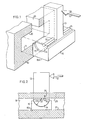
- Figure 1 illustrates schematically in perspective a first embodiment of a clutch arrangement according to the invention, in which the coupling element is shown in connection with the groove in which it is moved and clamped;
- Figure 2 is a side view of the arrangement illustrated in Fig. 1, with the upper and lower walls of the groove shown in section;
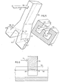
- Figure 3 is a schematic, perspective view of a second embodiment of the invention, illustrated in a similar manner to that in Fig. 1, wherewith this embodiment has gripping surfaces which clamp against mutually opposite sides of a flange;
- Figure 4 is a longitudinal sectional view through the guide and the coupling element illustrated in Fig. 3;
- Figure 5 is a schematic, perspective view of a third embodiment; and
- Figure 6 is a longitudinal sectional view of the third embodiment and the guide thereof.
- In the embodiments illustrated in Figures 1-6 one of the members capable of rectilinear or rotary movement relative to one another has the form of a rail or
bar arrow 12. In the Figures, thearrow 12 also represents, symbolically, the other of the aforesaid two members capable of rectilinear or rotational movement relative to one another. - In the embodiments illustrated in Figures 1-4, the gripping or clamping surfaces of the coupling element are located on two main components which can be rotated relative to one another and the common centre of rotation of which lies in the proximity of or in a plane extending through one guide surface of the aforesaid guide. In the embodiment illustrated in Figs. 5 and 6, the coupling element has the form of a single-piece structure.
- In the embodiment of Figs. 1 and 2 one
main component 14 of the coupling element has the form of an inverted-T, . thevertical leg 13 of which forms the lever-forming part of the coupling element, and the two transverse arms of which have a semi-cylindrical configuration. Arranged on the upper surfaces of the transverse arms of themain component 14 are rods which together form onegripping surface 15 of the coupling element. The other main component of the coupling element comprises a slide means 16 having on the upper surface thereof acylindrical recess 17 in which the semi-cylindrical transverse arms of themain component 14 are journalled, and a planar undersurface which forms the other clamping or grippingsurface 16a of the coupling element. As will be seen from Figs. 1 and 2, the coupling element can be moved in agroove 18 in therail 10, and firmly clamped in said groove. Therail 10 also has provided therein aslot 19 for accommodating theleg 13 of thecomponent 14. The mutually opposingwalls distal gripping surfaces - As will be seen from Fig. 2, the centre of rotation 22 of the semi-cylindrical transverse part of the
component 14 lies in the same plane as theguide surface 20. The radius of the cylinder surfaces is referenced 23. When theleg 13 of thecomponent 14 is acted upon by a force in the direction of thearrow 12, a clamping or grippingforce 24 is generated against theguide surface 20 at thegripping surface 15. Naturally, a corresponding force will be generated at thegripping surface 16a. Since the transverse part of thecomponent 14 rotates about a centre which lies in plane with theguide surface 20, thegripping surface 15 will move about the same centre and around a circle which cuts theguide surface 20 at its point of contact. At this point of contact, movement of thegripping surface 15 is commanded or controlled by the elastic deformation obtained in theguide surface 20 and in thegripping surface 15. Since this movement is extraordinarily slight it can be considered as a rectilinear, tangential movement, i.e. movement in a direction at right angles to theguide surface 20. As a result of this design of the clutch or coupling element, there will be no rubbing of the gripping surfaces against the guide surfaces during periods of increased load, right up to the moment when clamping is achieved. Minor deviations from the exact position of the centre 22 in the plane of theguide surface 20 are unavoidable, due to the varying accuracies in manufacture, and hence small deviations from the precise perpendicular location at which the gripping surface presses against the guide surface are considered to lie within the scope of the invention. - In the second embodiment, illustrated in Figs. 3 and 4, the one main component of the coupling element has the form of a double-plate component having a vertical portion comprising two mutually parallel, plate-
like legs shaft 27, by means of which force exerted thereon is transmitted to the coupling element, as indicated by thearrow 12. The inner ends of the legs are connected through acylinder segment 28, the planar upper side of which lies in the plane of the leg-end surfaces therelocated. Let into these end surfaces of the legs are two rods which form the one grippingsurface 29 of the coupling element. - Extending around the
cylinder segment 28 is a U-shaped stirrup which forms the other main component of the coupling element. The ends of the twoleg parts 30 of the stirrup are provided with T-shaped feet gripping surface 33 of the coupling element. - In the embodiment illustrated in Fig. 3 the rail or
bar 10 has-arranged therein an elongatedrectangular groove 34 for accommodating the lateral parts of thefeet slot 35 for accommodating thelegs 30. In the embodiment of Figs. 3 and 4, theundersurface 37 of therail 10 forms a guide surface for guiding thegripping surface 29 of the coupling element facing thegripping surface 33. Clamping will thus take place againstopposite sides 36, 37 of the two flange-like edge portions slit 35. - Rotation of one
main component 28 of the coupling element of this embodiment also takes place about a centre, here referenced 40, lying on the one guide surface, namely the downwardly facing,external guide surface 37. Thecylinder segment 28 and the inner surface of the central part of the stirrup have the same cylinder radius 41 with the centre atpoint 40. Thus thegripping surface 29 of this embodiment will also press against theguide surface 27 at substantially right-angles thereto under the elastic deformation occurring during clamping of the gripping surfaces. - In the embodiment illustrated in Figs. 5 and 6, the groove located in the rail or
bar 11 has arranged centrally thereof awall 42 which is located within the confines of a relativelywide slot 43, the width of which is greater than that of thecentral wall 42 so that the bifurcate coupling element, here in the form of a single-piece structure, can straddle the wall and ride thereon. Thus, thelegs 44,45 of the bifurcate coupling element extend into the groove in said rail, on either side of thecentral wall 42. The ends of thelegs 44,45 are provided withfeet 46,47 whose upper surfaces form grippingsurfaces 48, which lie against theundersurfaces 49 of theflanges 50 on therail 11. In addition, the coupling element has athird gripping surface 51, which is located at the end edge of therecess 52 located between thelegs 44,45, said end edge lying furthest away from the twogripping surfaces 48. In Fig. 5, the three gripping or clampingsurfaces surface 51 lies against theupper surface 53 of thecentral wall 42. - The three
guide surfaces rail 11 are spaced laterally, one from the other, and lie parallel with one another with said surfaces in substantially the same mutual plane, the two outer guide surfaces 49 facing in a direction opposite to that of theintermediate guide surface 53. - When a force is applied to the lever-forming
leg 54 of the coupling element in the direction of thearrow 12, the rocking movement caused by the elastic deformation created by clamping the coupling element will be minimal. In this respect, the coupling element is rocked around the grippingsurface 51, with said surface as the centre of rotation, while the grippingsurface 48 is pressed against theguide surface 49 at right angles thereto. Thus, the aforementioned disadvantages encountered with the coupling elements of known clutch arrangements are also avoided with this embodiment.
Claims (7)
Priority Applications (1)
| Application Number | Priority Date | Filing Date | Title |
|---|---|---|---|
| AT84850399T ATE43411T1 (en) | 1983-12-22 | 1984-12-21 | LOCKING DEVICE, ESPECIALLY FOR STEPLESS ADJUSTMENT. |
Applications Claiming Priority (2)
| Application Number | Priority Date | Filing Date | Title |
|---|---|---|---|
| SE8307120A SE440542B (en) | 1983-12-22 | 1983-12-22 | CLUTCH DEVICE, SPECIFICALLY FOR STEELLESS ADJUSTABLE SWITCH |
| SE8307120 | 1983-12-22 |
Publications (2)
| Publication Number | Publication Date |
|---|---|
| EP0154106A1 true EP0154106A1 (en) | 1985-09-11 |
| EP0154106B1 EP0154106B1 (en) | 1989-05-24 |
Family
ID=20353862
Family Applications (1)
| Application Number | Title | Priority Date | Filing Date |
|---|---|---|---|
| EP84850399A Expired EP0154106B1 (en) | 1983-12-22 | 1984-12-21 | Coupling device, especially for steplessly adjustable displacement |
Country Status (6)
| Country | Link |
|---|---|
| US (1) | US4635772A (en) |
| EP (1) | EP0154106B1 (en) |
| JP (1) | JPS60172730A (en) |
| AT (1) | ATE43411T1 (en) |
| DE (1) | DE3478333D1 (en) |
| SE (1) | SE440542B (en) |
Cited By (2)
| Publication number | Priority date | Publication date | Assignee | Title |
|---|---|---|---|---|
| DE8803070U1 (en) * | 1988-03-08 | 1988-04-21 | Farmont Produktion Gmbh & Co Kg, 4000 Duesseldorf, De | |
| WO2004076884A1 (en) * | 2003-02-28 | 2004-09-10 | Gadloc Ab | A frictional engagement device |
Families Citing this family (2)
| Publication number | Priority date | Publication date | Assignee | Title |
|---|---|---|---|---|
| US9982722B2 (en) | 2013-07-09 | 2018-05-29 | Solarcity Corporation | Torque transfer in laterally engaging drive couplers exhibiting axial misalignment with driven couplers |
| US9222523B2 (en) | 2013-07-09 | 2015-12-29 | Solarcity, Inc. | Dual-mode torque transfer in laterally engaging drive couplers exhibiting axial misalignment with driven couplers |
Citations (8)
| Publication number | Priority date | Publication date | Assignee | Title |
|---|---|---|---|---|
| DE817981C (en) * | 1947-06-20 | 1951-10-22 | Allg Kunstzijde Unie N V | Lock |
| GB671161A (en) * | 1949-06-07 | 1952-04-30 | Andre Felix | Improvements in or relating to supports for shelving |
| DE1008535B (en) * | 1955-08-24 | 1957-05-16 | Walter Fischer | Arrangement for guiding and clamping a component on a column |
| FR1385006A (en) * | 1964-02-10 | 1965-01-08 | Stem instantly adjustable on column | |
| CH422259A (en) * | 1964-10-05 | 1966-10-15 | Ferrotechnik Ag | Storage rack |
| US3429540A (en) * | 1966-05-30 | 1969-02-25 | Worrallo A C | Self-locking bracket and the like |
| GB1560724A (en) * | 1977-04-06 | 1980-02-06 | Swish Prod | Adjustable bracket assembly |
| US4413819A (en) * | 1981-04-09 | 1983-11-08 | Kurt Manufacturing Company, Inc. | Vise clamp and swivel base vise using such clamp |
Family Cites Families (2)
| Publication number | Priority date | Publication date | Assignee | Title |
|---|---|---|---|---|
| US768929A (en) * | 1904-02-02 | 1904-08-30 | Alfred Breese | Adjustable bracket. |
| IL50351A (en) * | 1976-08-24 | 1979-01-31 | Mochly J | Wall bracket and its support |
-
1983
- 1983-12-22 SE SE8307120A patent/SE440542B/en not_active IP Right Cessation
-
1984
- 1984-12-19 US US06/683,620 patent/US4635772A/en not_active Expired - Fee Related
- 1984-12-20 JP JP59267640A patent/JPS60172730A/en active Pending
- 1984-12-21 AT AT84850399T patent/ATE43411T1/en not_active IP Right Cessation
- 1984-12-21 DE DE8484850399T patent/DE3478333D1/en not_active Expired
- 1984-12-21 EP EP84850399A patent/EP0154106B1/en not_active Expired
Patent Citations (8)
| Publication number | Priority date | Publication date | Assignee | Title |
|---|---|---|---|---|
| DE817981C (en) * | 1947-06-20 | 1951-10-22 | Allg Kunstzijde Unie N V | Lock |
| GB671161A (en) * | 1949-06-07 | 1952-04-30 | Andre Felix | Improvements in or relating to supports for shelving |
| DE1008535B (en) * | 1955-08-24 | 1957-05-16 | Walter Fischer | Arrangement for guiding and clamping a component on a column |
| FR1385006A (en) * | 1964-02-10 | 1965-01-08 | Stem instantly adjustable on column | |
| CH422259A (en) * | 1964-10-05 | 1966-10-15 | Ferrotechnik Ag | Storage rack |
| US3429540A (en) * | 1966-05-30 | 1969-02-25 | Worrallo A C | Self-locking bracket and the like |
| GB1560724A (en) * | 1977-04-06 | 1980-02-06 | Swish Prod | Adjustable bracket assembly |
| US4413819A (en) * | 1981-04-09 | 1983-11-08 | Kurt Manufacturing Company, Inc. | Vise clamp and swivel base vise using such clamp |
Cited By (3)
| Publication number | Priority date | Publication date | Assignee | Title |
|---|---|---|---|---|
| DE8803070U1 (en) * | 1988-03-08 | 1988-04-21 | Farmont Produktion Gmbh & Co Kg, 4000 Duesseldorf, De | |
| WO2004076884A1 (en) * | 2003-02-28 | 2004-09-10 | Gadloc Ab | A frictional engagement device |
| US7360634B2 (en) | 2003-02-28 | 2008-04-22 | Gadloc Ab | Frictional engagement device |
Also Published As
| Publication number | Publication date |
|---|---|
| SE8307120L (en) | 1985-06-23 |
| DE3478333D1 (en) | 1989-06-29 |
| SE440542B (en) | 1985-08-05 |
| JPS60172730A (en) | 1985-09-06 |
| EP0154106B1 (en) | 1989-05-24 |
| US4635772A (en) | 1987-01-13 |
| ATE43411T1 (en) | 1989-06-15 |
| SE8307120D0 (en) | 1983-12-22 |
Similar Documents
| Publication | Publication Date | Title |
|---|---|---|
| US6148708A (en) | Cutting apparatus with motor | |
| EP0626526B1 (en) | Drive belt | |
| JP3284444B2 (en) | Energy guide chains with guide stops | |
| NL7900923A (en) | COMPOSITE DRIVE BELT PROVIDED WITH CROSS-ELEMENTS WITH COUPLERS, AND CROSS-ELEMENT FOR A BELT. | |
| SE8103600L (en) | CHAIN CHAIN FOR STEPLESS ADJUSTABLE DRIVE DEVICES WITH CONIC DISC | |
| EP0154106A1 (en) | Coupling device, especially for steplessly adjustable displacement | |
| DE3167953D1 (en) | Device for gradually adjusting the distance between two chair-parts | |
| DE3438786A1 (en) | CHAIN CONVEYOR FOR WORKPIECES AND WORKPIECE CARRIERS | |
| SE8204028D0 (en) | LASCHENKETTE FOR STUFENLOS ADJUSTABLE TAPE | |
| GB2165025A (en) | An arrangement for transmitting torque between conical pulleys in a transmission mechanism | |
| US3688595A (en) | Infinitely variable chain-engaged gearing | |
| SE463501B (en) | ENGINE DRIVING CASE | |
| DE2412576A1 (en) | VEHICLE DISC BRAKE | |
| EP0448208B1 (en) | Chain-belt | |
| US5439422A (en) | Drive belt | |
| US3939721A (en) | Master link assembly | |
| DE2517910A1 (en) | Overload safety clutch with slipping rollers - reduces roller wear by relieving spring load during torque overload | |
| US4473366A (en) | Flexible drive belt | |
| EP0448199A3 (en) | Chain-belt | |
| NL8400795A (en) | V-BELT TRANSMISSION GEAR. | |
| JP3283560B2 (en) | Chain belt | |
| US4180110A (en) | Handsaw with specialized cutting teeth | |
| EP0212719A2 (en) | Driving device for a domestic vibration apparatus | |
| US4088034A (en) | Chain drive for a workpiece transfer mechanism | |
| US4986799A (en) | Transmission chain with pivot pins and intermediate pieces with rolling contact action |
Legal Events
| Date | Code | Title | Description |
|---|---|---|---|
| PUAI | Public reference made under article 153(3) epc to a published international application that has entered the european phase |
Free format text: ORIGINAL CODE: 0009012 |
|
| AK | Designated contracting states |
Designated state(s): AT BE CH DE FR GB IT LI LU NL SE |
|
| 17P | Request for examination filed |
Effective date: 19860218 |
|
| 17Q | First examination report despatched |
Effective date: 19870521 |
|
| GRAA | (expected) grant |
Free format text: ORIGINAL CODE: 0009210 |
|
| AK | Designated contracting states |
Kind code of ref document: B1 Designated state(s): AT BE CH DE FR GB IT LI LU NL SE |
|
| PG25 | Lapsed in a contracting state [announced via postgrant information from national office to epo] |
Ref country code: SE Effective date: 19890524 |
|
| REF | Corresponds to: |
Ref document number: 43411 Country of ref document: AT Date of ref document: 19890615 Kind code of ref document: T |
|
| REF | Corresponds to: |
Ref document number: 3478333 Country of ref document: DE Date of ref document: 19890629 |
|
| ITF | It: translation for a ep patent filed |
Owner name: BARZANO' E ZANARDO ROMA S.P.A. |
|
| ET | Fr: translation filed | ||
| PGFP | Annual fee paid to national office [announced via postgrant information from national office to epo] |
Ref country code: LU Payment date: 19891206 Year of fee payment: 6 |
|
| PGFP | Annual fee paid to national office [announced via postgrant information from national office to epo] |
Ref country code: CH Payment date: 19891213 Year of fee payment: 6 |
|
| PGFP | Annual fee paid to national office [announced via postgrant information from national office to epo] |
Ref country code: BE Payment date: 19891218 Year of fee payment: 6 |
|
| PGFP | Annual fee paid to national office [announced via postgrant information from national office to epo] |
Ref country code: AT Payment date: 19891222 Year of fee payment: 6 |
|
| PGFP | Annual fee paid to national office [announced via postgrant information from national office to epo] |
Ref country code: FR Payment date: 19891226 Year of fee payment: 6 |
|
| ITTA | It: last paid annual fee | ||
| PG25 | Lapsed in a contracting state [announced via postgrant information from national office to epo] |
Ref country code: LU Free format text: LAPSE BECAUSE OF NON-PAYMENT OF DUE FEES Effective date: 19891231 |
|
| PGFP | Annual fee paid to national office [announced via postgrant information from national office to epo] |
Ref country code: NL Payment date: 19891231 Year of fee payment: 6 Ref country code: GB Payment date: 19891231 Year of fee payment: 6 |
|
| PGFP | Annual fee paid to national office [announced via postgrant information from national office to epo] |
Ref country code: DE Payment date: 19900125 Year of fee payment: 6 |
|
| PLBE | No opposition filed within time limit |
Free format text: ORIGINAL CODE: 0009261 |
|
| STAA | Information on the status of an ep patent application or granted ep patent |
Free format text: STATUS: NO OPPOSITION FILED WITHIN TIME LIMIT |
|
| 26N | No opposition filed | ||
| PG25 | Lapsed in a contracting state [announced via postgrant information from national office to epo] |
Ref country code: GB Effective date: 19901221 Ref country code: AT Effective date: 19901221 |
|
| PG25 | Lapsed in a contracting state [announced via postgrant information from national office to epo] |
Ref country code: LI Effective date: 19901231 Ref country code: CH Effective date: 19901231 Ref country code: BE Effective date: 19901231 |
|
| BERE | Be: lapsed |
Owner name: GADELIUS GUSTAF Effective date: 19901231 |
|
| PG25 | Lapsed in a contracting state [announced via postgrant information from national office to epo] |
Ref country code: NL Effective date: 19910701 |
|
| NLV4 | Nl: lapsed or anulled due to non-payment of the annual fee | ||
| GBPC | Gb: european patent ceased through non-payment of renewal fee | ||
| PG25 | Lapsed in a contracting state [announced via postgrant information from national office to epo] |
Ref country code: FR Effective date: 19910830 |
|
| REG | Reference to a national code |
Ref country code: CH Ref legal event code: PL |
|
| PG25 | Lapsed in a contracting state [announced via postgrant information from national office to epo] |
Ref country code: DE Effective date: 19910903 |
|
| REG | Reference to a national code |
Ref country code: FR Ref legal event code: ST |