EP0153662A1 - Rotary support device - Google Patents
Rotary support device Download PDFInfo
- Publication number
- EP0153662A1 EP0153662A1 EP85101580A EP85101580A EP0153662A1 EP 0153662 A1 EP0153662 A1 EP 0153662A1 EP 85101580 A EP85101580 A EP 85101580A EP 85101580 A EP85101580 A EP 85101580A EP 0153662 A1 EP0153662 A1 EP 0153662A1
- Authority
- EP
- European Patent Office
- Prior art keywords
- retainer
- support device
- rotary support
- ring
- portions
- Prior art date
- Legal status (The legal status is an assumption and is not a legal conclusion. Google has not performed a legal analysis and makes no representation as to the accuracy of the status listed.)
- Granted
Links
- 230000002093 peripheral effect Effects 0.000 claims abstract description 34
- 229910000831 Steel Inorganic materials 0.000 claims abstract description 24
- 239000010959 steel Substances 0.000 claims abstract description 24
- 238000003825 pressing Methods 0.000 claims description 8
- 229920003002 synthetic resin Polymers 0.000 claims description 4
- 239000000057 synthetic resin Substances 0.000 claims description 4
- 238000004519 manufacturing process Methods 0.000 claims description 3
- 238000000034 method Methods 0.000 description 4
- 238000005096 rolling process Methods 0.000 description 3
- 238000005520 cutting process Methods 0.000 description 2
- VYZAMTAEIAYCRO-UHFFFAOYSA-N Chromium Chemical compound [Cr] VYZAMTAEIAYCRO-UHFFFAOYSA-N 0.000 description 1
- 238000005299 abrasion Methods 0.000 description 1
- 239000000853 adhesive Substances 0.000 description 1
- 230000001070 adhesive effect Effects 0.000 description 1
- 229910052804 chromium Inorganic materials 0.000 description 1
- 239000011651 chromium Substances 0.000 description 1
- 239000010960 cold rolled steel Substances 0.000 description 1
- 238000010586 diagram Methods 0.000 description 1
- 238000006073 displacement reaction Methods 0.000 description 1
- 238000001746 injection moulding Methods 0.000 description 1
- 238000005304 joining Methods 0.000 description 1
- 238000012986 modification Methods 0.000 description 1
- 230000004048 modification Effects 0.000 description 1
- 238000007747 plating Methods 0.000 description 1
- 238000000926 separation method Methods 0.000 description 1
- 239000002699 waste material Substances 0.000 description 1
- 238000003466 welding Methods 0.000 description 1
Images


Classifications
-
- B—PERFORMING OPERATIONS; TRANSPORTING
- B65—CONVEYING; PACKING; STORING; HANDLING THIN OR FILAMENTARY MATERIAL
- B65G—TRANSPORT OR STORAGE DEVICES, e.g. CONVEYORS FOR LOADING OR TIPPING, SHOP CONVEYOR SYSTEMS OR PNEUMATIC TUBE CONVEYORS
- B65G29/00—Rotary conveyors, e.g. rotating discs, arms, star-wheels or cones
-
- F—MECHANICAL ENGINEERING; LIGHTING; HEATING; WEAPONS; BLASTING
- F16—ENGINEERING ELEMENTS AND UNITS; GENERAL MEASURES FOR PRODUCING AND MAINTAINING EFFECTIVE FUNCTIONING OF MACHINES OR INSTALLATIONS; THERMAL INSULATION IN GENERAL
- F16M—FRAMES, CASINGS OR BEDS OF ENGINES, MACHINES OR APPARATUS, NOT SPECIFIC TO ENGINES, MACHINES OR APPARATUS PROVIDED FOR ELSEWHERE; STANDS; SUPPORTS
- F16M11/00—Stands or trestles as supports for apparatus or articles placed thereon ; Stands for scientific apparatus such as gravitational force meters
- F16M11/02—Heads
- F16M11/04—Means for attachment of apparatus; Means allowing adjustment of the apparatus relatively to the stand
- F16M11/06—Means for attachment of apparatus; Means allowing adjustment of the apparatus relatively to the stand allowing pivoting
- F16M11/08—Means for attachment of apparatus; Means allowing adjustment of the apparatus relatively to the stand allowing pivoting around a vertical axis, e.g. panoramic heads
-
- A—HUMAN NECESSITIES
- A47—FURNITURE; DOMESTIC ARTICLES OR APPLIANCES; COFFEE MILLS; SPICE MILLS; SUCTION CLEANERS IN GENERAL
- A47B—TABLES; DESKS; OFFICE FURNITURE; CABINETS; DRAWERS; GENERAL DETAILS OF FURNITURE
- A47B49/00—Revolving cabinets or racks; Cabinets or racks with revolving parts
-
- F—MECHANICAL ENGINEERING; LIGHTING; HEATING; WEAPONS; BLASTING
- F16—ENGINEERING ELEMENTS AND UNITS; GENERAL MEASURES FOR PRODUCING AND MAINTAINING EFFECTIVE FUNCTIONING OF MACHINES OR INSTALLATIONS; THERMAL INSULATION IN GENERAL
- F16C—SHAFTS; FLEXIBLE SHAFTS; ELEMENTS OR CRANKSHAFT MECHANISMS; ROTARY BODIES OTHER THAN GEARING ELEMENTS; BEARINGS
- F16C19/00—Bearings with rolling contact, for exclusively rotary movement
- F16C19/02—Bearings with rolling contact, for exclusively rotary movement with bearing balls essentially of the same size in one or more circular rows
- F16C19/10—Bearings with rolling contact, for exclusively rotary movement with bearing balls essentially of the same size in one or more circular rows for axial load mainly
-
- F—MECHANICAL ENGINEERING; LIGHTING; HEATING; WEAPONS; BLASTING
- F16—ENGINEERING ELEMENTS AND UNITS; GENERAL MEASURES FOR PRODUCING AND MAINTAINING EFFECTIVE FUNCTIONING OF MACHINES OR INSTALLATIONS; THERMAL INSULATION IN GENERAL
- F16C—SHAFTS; FLEXIBLE SHAFTS; ELEMENTS OR CRANKSHAFT MECHANISMS; ROTARY BODIES OTHER THAN GEARING ELEMENTS; BEARINGS
- F16C33/00—Parts of bearings; Special methods for making bearings or parts thereof
- F16C33/30—Parts of ball or roller bearings
- F16C33/38—Ball cages
- F16C33/3812—Ball cages formed of interconnected segments, e.g. chains
-
- F—MECHANICAL ENGINEERING; LIGHTING; HEATING; WEAPONS; BLASTING
- F16—ENGINEERING ELEMENTS AND UNITS; GENERAL MEASURES FOR PRODUCING AND MAINTAINING EFFECTIVE FUNCTIONING OF MACHINES OR INSTALLATIONS; THERMAL INSULATION IN GENERAL
- F16C—SHAFTS; FLEXIBLE SHAFTS; ELEMENTS OR CRANKSHAFT MECHANISMS; ROTARY BODIES OTHER THAN GEARING ELEMENTS; BEARINGS
- F16C33/00—Parts of bearings; Special methods for making bearings or parts thereof
- F16C33/30—Parts of ball or roller bearings
- F16C33/58—Raceways; Race rings
- F16C33/588—Races of sheet metal
-
- F—MECHANICAL ENGINEERING; LIGHTING; HEATING; WEAPONS; BLASTING
- F16—ENGINEERING ELEMENTS AND UNITS; GENERAL MEASURES FOR PRODUCING AND MAINTAINING EFFECTIVE FUNCTIONING OF MACHINES OR INSTALLATIONS; THERMAL INSULATION IN GENERAL
- F16C—SHAFTS; FLEXIBLE SHAFTS; ELEMENTS OR CRANKSHAFT MECHANISMS; ROTARY BODIES OTHER THAN GEARING ELEMENTS; BEARINGS
- F16C33/00—Parts of bearings; Special methods for making bearings or parts thereof
- F16C33/72—Sealings
- F16C33/76—Sealings of ball or roller bearings
- F16C33/761—Sealings of ball or roller bearings specifically for bearings with purely axial load
-
- F—MECHANICAL ENGINEERING; LIGHTING; HEATING; WEAPONS; BLASTING
- F16—ENGINEERING ELEMENTS AND UNITS; GENERAL MEASURES FOR PRODUCING AND MAINTAINING EFFECTIVE FUNCTIONING OF MACHINES OR INSTALLATIONS; THERMAL INSULATION IN GENERAL
- F16C—SHAFTS; FLEXIBLE SHAFTS; ELEMENTS OR CRANKSHAFT MECHANISMS; ROTARY BODIES OTHER THAN GEARING ELEMENTS; BEARINGS
- F16C33/00—Parts of bearings; Special methods for making bearings or parts thereof
- F16C33/72—Sealings
- F16C33/76—Sealings of ball or roller bearings
- F16C33/80—Labyrinth sealings
-
- F—MECHANICAL ENGINEERING; LIGHTING; HEATING; WEAPONS; BLASTING
- F16—ENGINEERING ELEMENTS AND UNITS; GENERAL MEASURES FOR PRODUCING AND MAINTAINING EFFECTIVE FUNCTIONING OF MACHINES OR INSTALLATIONS; THERMAL INSULATION IN GENERAL
- F16M—FRAMES, CASINGS OR BEDS OF ENGINES, MACHINES OR APPARATUS, NOT SPECIFIC TO ENGINES, MACHINES OR APPARATUS PROVIDED FOR ELSEWHERE; STANDS; SUPPORTS
- F16M2200/00—Details of stands or supports
- F16M2200/08—Foot or support base
Definitions
- Devices for rotatably supporting articles which comprise a base plate formed with an annular recessed portion and steel balls arranged on the recessed portion at a specified pitch so that the article can be rotatably supported by the steel balls, as disclosed in British Patent No. 1,231,388 and Swiss Patent No. 159,371.
- these devices in which the article and the base plate are united, have the problem of being unsuited to universal use.
- the rotating apparatus comprises an under ring 81 serving as an under member, a plurality of roller bearings 8 mounted on the under ring 81 in vertical and horizontal positions, an upper ring 80 supported by the bearings and serving as an upper member, and a retaining member 82 for holding the two rings together.
- the apparatus is annular in its entirety and can be transported by rolling. Moreover, when a pallet is placed on the upper ring 80, a heavy article such as a drum can be rotatably supported by the apparatus.
- the apparatus which includes the plurality of roller bearings, has a problem in respect of cost because the bearings and the retaining member 82 must be fixed to the rings by an expensive manual procedure.
- a reduction of production costs is achieved by a rotary support device according to the present invention as defined in claims 1 and 2 and by a manufacturing method diclosed in claim 8.
- the inner peripheries or outer peripheries of an annular upper member and an annular under member are bent toward each other to form a lap, and the lapping peripheral edges are bent toward each other to thereby form a pair of retaining portions which are rotatable relative to each other.
- a plurality of steel balls held equidistantly spaced apart by a retainer are rollably arranged between the two members.
- Fig. 1 shows a rotary support device of the present invention supporting a table 7 for placing an article thereon.
- a plurality of steel balls 3 are arranged at a definite spacing between an upper ring 1 and an under ring 2 which serve as an annular upper member and an annular under member, respectively.
- a retainer 5 for rollably holding these steel balls 3 at a definite position relative to the retainer.
- the two rings 1, 2 comprise annular horizontal walls 15, 25 formed with annular recessed portions 12, 22 for guiding the rolling movement of the steel balls 3, and vertical inner peripheral walls 11, 21 and vertical outer peripheral walls 10, 20 respectively bent.at the inner and outer peripheries of the horizontal walls and each extending toward the opposed ring.
- the inner peripheral walls 11, 21, as well as the outer peripheral walls 10, 20, of the two rings 1, 2 lap over each other with a small clearance formed therebetween.
- Each of the inner peripheral walls 11, 21 and/or the outer peripheral walls 10, 20 is bent at its edge portion toward the other opposed lapping peripheral wall in a direction to engage therewith to thereby form a pair of annular retaining portions 13, 23 each positioned inwardly of the opposed peripheral wall beyond the extremity thereof by a small dimension t.
- each of the upper ring 1 and the under ring 2 is formed by blanking out a ring from a cold-rolled steel sheet having a thickness of 2.3 mm and pressing the blank.
- the device as assembled is 499 mm in outside diameter, 359 mm in inside diameter and about 20 mm in thickness.
- Fourty-five steel balls 3, about 15.9 mm in diameter, are arranged at a pitch of about 28.2 mm and held by the retainer 5 in position relative to the retainer.
- the vertical inner peripheral walls 11, 21 of the rings 1, 2 overlap each other as spaced apart by a clearance u of about 0.9 to 1.3 mm radially of the rings.
- the vertical outer peripheral walls 10, 20 are bent toward each other at a position 5 mm away from their extremities to overlap each other by the dimension t of about 1.4 to 2.0 mm radially of the rings.
- the under ring 2 is prepared from a steel plate 90 blanked out in an annular form, by a single pressing process.
- a steel plate 9 blanked out in an annular form is subjected to a first pressing process to obtain a semi-finished ring 91 in which the horizontal wall 15 and the vertical outer peripheral wall 10 form an angle a of about 92 to 95 degrees as seen in Fig. 4.
- the retainer 5 and steel balls 3 are arranged on the under ring 2, and the semi-finished upper ring 91 is placed over the resulting assembly as shown in Fig. 4.
- the semi-finished upper ring 91 is fittable over the under ring 2.
- the vertical outer peripheral wall 10 of the semi-finished ring 91 is then subjected over the entire circumference thereof to a second pressing process for plastic working to engage the retaining portions 13, 23 of the two rings with each other by reducing the angle a between the outer peripheral wall 10 and the horizontal wall 15 to about 90 as shown in Fig. 5, whereby the finished product of Fig. 2 is obtained.
- the upper ring 1 and the under ring 2 are freely rotatable relative to each other as.supported by the steel balls, with a clearance u formed between their inner peripheral walls.
- the retaining portions 13, 23 overlap each other radially of the rings over the entire circumference thereof, the two rings are prevented from separation by the retaining portions coming into contact with each other even when a separating force acts on the rings.
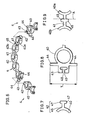
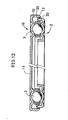
- the retainer 5 comprises a plurality of retainer segments 4 connected to one another into a ring as seen in Fig. 6.
- the retainer segment 4 is integrally molded of a synthetic resin and comprises a plurality of hollow cylindrical holding portions 40 arranged on a plane and interconnected in a row by flexible thin connecting portions 41.
- An engaging piece 42 and a socket piece 43 engageable with each other are provided at opposite ends of the segment 4.as shown in Fig. 6.
- the engaging piece 42 includes a thin plate-like stem 46 having the same thickness as the connecting portion 41 and protrusions 47 which are circular arc in section and provided on opposite sides of the forward end of the stem 46.
- Fig. 8 shows that the socket piece 43 has a first socket 48 for the stem 46 of the engaging piece 42 to fit in and an enlarged second socket 49 for the protrusions 47 to fit in.
- the connecting portion 41 between a first holding portion 40a provided with the engaging piece 42 and a second holding portion 40b subsequent to the portion 40a is formed with protrusions 45 on its opposite sides.
- the connecting portion 41 is cut along the broken line A shown, the remaining portion on the second holding portion 40b can be made to have the same shape as the engaging piece 42.
- a pair of projections 44, 44 in the form of a thin plate extends from the base end of the socket piece 43 at right angles with the direction of arrangement of the holding portions 40.
- the end-to-end overall length T of the projections 44, 44 is slightly smaller than the distance between the inner surfaces of the under ring 2 shown in Fig. 2.
- the retainer segment 4 is arcuate in its entirety. Moreover, since the connecting portions 41 are made of a synthetic resin, the retainer segment 4 is further deformable. Accordingly the.retainer 5 is formed by connecting a plurality of retainer segments 4 into a single elongated assembly by the engagement of engaging pieces 42 with socket pieces 43 and engaging the ends of the assembly with each other into a ring. The retainer 5 is interposed between the under ring 2 and the upper ring 1 and rollably holds the steel balls 3 at an equal spacing.
- the diameter of the retainer 5 is adjustable in accordance with the sizes of the under ring 2 and the upper ring 1 by cutting the connecting portion 41 having the protrusions 45 and included in the retainer segment 4 and using the protrusions for engagement.
- each retainer segment 4 When the retainer 5 is provided between the under ring 2 and the upper ring 1, the projections 44, 44 formed at one end of each retainer segment 4 are opposed to the vertical inner peripheral wall 21 and the outer peripheral wall 20 of the under ring 2 in contact therewith or as spaced apart therefrom by a small clearance as shown in Fig. 2, whereby the retainer 5 interposed between the rings is prevented from displacement. Accordingly even when impact acts on the rotary support device radially of the rings for example when the device is carried around, the retainer .5 reliably holds the steel balls 3 arranged concentrically with the rings without permitting them to deviate from the circular raceways formed on the rings.
- a table 7 is placed on the rotary support device as shown in Fig. 1.
- the upper ring 1 rotates smoothly relative to the under ring 2 owing to the rolling movement of the steel balls 3. Even if the load is applied to the upper ring 1 in a somewhat inclined direction relative to the center of rotation of the ring, the rings will not be displaced since the steel balls 3 are restrained by the annular recessed portions 12, 22 of the rings.
- the retaining portions can be easily formed by press work at the edges of the upper ring and the under ring. This reduces the number of components and renders the device easy and inexpensive to make. Moreover, the device is annular in its entirety and is therefore convenient to carry around.
- the retainer 5 can be formed from a synthetic resin easily, for example, by injection molding and is accordingly inexpensive to make.
- the diameter of the retainer 5 as an assembly is easily adjustable by changing the number of retainer segments 4 or by cutting the connecting portion 41 having the protrusions 45.
- the retainer 5 is well suited to the present device.
- outward or inward flanges 6 are attached to the upper ring 1 or the under ring 2 as seen in Figs. 1 and 10.
- the flange attaching portion of the ring is recessed by an amount corresponding to the thickness of the flange as shown in Fig. 10, so that the lower surface of the device has no stepped portion.
- the retaining portions 13, 23, which are formed on the outer peripheral walls 10, 20 in the foregoing embodiment, may alternatively be formed on the inner peripheral walls 11, 21 as seen in Fig. 11.
- rings are blanked out from a steel sheet to obtain workpieces for press work, so that the disks blanked out for forming the central openings are unusable.
- the waste of steel sheet due to blanking can be reduced by blanking out sectors from a steel sheet, pressing the blanks and joining the pressed blanks into a ring by welding.
- the raceways for the steel balls can be given improved resistance to abrasion and fatigue by subjecting the upper ring and the under ring to tufftriding treatment or plating the rings with hard chromium.
- the engaging piece 42 and the socket piece 43 of the retainer segment 4 have the first protrusions 47 and the socket 49, respectively, for preventing slipping off
- the engaging portions may be made separable in the direction of connecting retainer segments and bonded together with an adhesive when required for assembly, instead of forming the protrusions and socket.
- the second protrusions 45 need not be provided on the connecting portion 41.
- the projections 44 of the retainer segment 4 need not always be formed on the socket piece 43 but can of course be provided on the holding portion 40 or the connecting portion 41.
- the projections 44 are not always necessary, it is desirable to provide these projections to assure more reliable operation of the device.
- the second protrusions 45 need not be formed on the retainer segment 4, while the retainer can be molded as an integral piece in its entirety.
- the under ring 2 and the upper ring 1 are not always in a fixed upper-lower relationship; the upper ring 1 of the rotary support device is of course usable as the under ring.
- One or both of the upper and under member can be of a shape other than a ring having a central opening.
- Fig. 12 shows a disk-like member 16 having a top wall 17 at its central . portion and serving as the upper member.
- the member 16 can be formed from a steel sheet by press work. An article can be placed directly at the center of the upper member thus formed without using any table.
Landscapes
- Engineering & Computer Science (AREA)
- General Engineering & Computer Science (AREA)
- Mechanical Engineering (AREA)
- Rolling Contact Bearings (AREA)
Abstract
Description
- Devices for rotatably supporting articles have heretofore been proposed which comprise a base plate formed with an annular recessed portion and steel balls arranged on the recessed portion at a specified pitch so that the article can be rotatably supported by the steel balls, as disclosed in British Patent No. 1,231,388 and Swiss Patent No. 159,371. However, these devices, in which the article and the base plate are united, have the problem of being unsuited to universal use.
- Accordingly the present applicant has already proposed a rotating apparatus which is universally usable and shown in Fig. 13. The apparatus is disclosed in detail in the specification of U.S. Patent No. 4,433,954.
- With reference to Fig. 13, the rotating apparatus comprises an under
ring 81 serving as an under member, a plurality of roller bearings 8 mounted on the underring 81 in vertical and horizontal positions, anupper ring 80 supported by the bearings and serving as an upper member, and a retainingmember 82 for holding the two rings together. The apparatus is annular in its entirety and can be transported by rolling. Moreover, when a pallet is placed on theupper ring 80, a heavy article such as a drum can be rotatably supported by the apparatus. However, the apparatus, which includes the plurality of roller bearings, has a problem in respect of cost because the bearings and the retainingmember 82 must be fixed to the rings by an expensive manual procedure. - A reduction of production costs is achieved by a rotary support device according to the present invention as defined in
claims 1 and 2 and by a manufacturing method diclosed in claim 8. - According to the present invention, the inner peripheries or outer peripheries of an annular upper member and an annular under member are bent toward each other to form a lap, and the lapping peripheral edges are bent toward each other to thereby form a pair of retaining portions which are rotatable relative to each other. A plurality of steel balls held equidistantly spaced apart by a retainer are rollably arranged between the two members.
-
- Fig. 1 is a perspective view partly broken away and showing a rotary support device;
- Fig. 2 is an enlarged sectional view of Fig. 1;
- Fig. 3 is a perspective view showing steel plates before press work;
- Fig. 4 is an enlarged sectional view showing an upper ring and an under ring before fitting;
- Fig. 5 is a diagram illustrating how to form retaining portions;
- Fig. 6 is a perspective view showing a retainer;
- Fig. 7 is a plan view showing an engaging piece of the retainer;
- Fig. 8 is a plan view showing a socket piece of the retainer;
- Fig. 9 is a plan view showing a retainer connecting portion having protrusions;
- Fig. 10 is a sectional view showing a rotary support device having a flange on an under ring;
- Fig. 11 is an enlarged sectional view showing another embodiment;
- Fig. 12 is an enlarged sectional view showing an embodiment wherein an upper member is formed with a top wall; and
- Fig. 13 is a sectional view showing a known rotating apparatus already proposed by the present inventor.
- Fig. 1 shows a rotary support device of the present invention supporting a table 7 for placing an article thereon.
- A plurality of
steel balls 3 are arranged at a definite spacing between an upper ring 1 and an underring 2 which serve as an annular upper member and an annular under member, respectively. Interposed between the two rings is aretainer 5 for rollably holding thesesteel balls 3 at a definite position relative to the retainer. The tworings 1, 2 comprise annularhorizontal walls portions steel balls 3, and vertical innerperipheral walls peripheral walls peripheral walls peripheral walls rings 1, 2 lap over each other with a small clearance formed therebetween. Each of the innerperipheral walls peripheral walls retaining portions - According to the present embodiment, each of the upper ring 1 and the under
ring 2 is formed by blanking out a ring from a cold-rolled steel sheet having a thickness of 2.3 mm and pressing the blank. The device as assembled is 499 mm in outside diameter, 359 mm in inside diameter and about 20 mm in thickness. Fourty-fivesteel balls 3, about 15.9 mm in diameter, are arranged at a pitch of about 28.2 mm and held by theretainer 5 in position relative to the retainer. - The vertical inner
peripheral walls rings 1, 2 overlap each other as spaced apart by a clearance u of about 0.9 to 1.3 mm radially of the rings. The vertical outerperipheral walls position 5 mm away from their extremities to overlap each other by the dimension t of about 1.4 to 2.0 mm radially of the rings. - As seen in Fig. 3, the under
ring 2 is prepared from asteel plate 90 blanked out in an annular form, by a single pressing process. To prepare the upper ring 1, on the other hand, a steel plate 9 blanked out in an annular form is subjected to a first pressing process to obtain asemi-finished ring 91 in which thehorizontal wall 15 and the vertical outerperipheral wall 10 form an angle a of about 92 to 95 degrees as seen in Fig. 4. Subsequently theretainer 5 andsteel balls 3 are arranged on the underring 2, and the semi-finishedupper ring 91 is placed over the resulting assembly as shown in Fig. 4. Since the retainingportion 13 of thesemi-finished ring 91 has a larger diameter than theretaining portion 23 of the underring 2, the semi-finishedupper ring 91 is fittable over the underring 2. The vertical outerperipheral wall 10 of thesemi-finished ring 91 is then subjected over the entire circumference thereof to a second pressing process for plastic working to engage the retainingportions peripheral wall 10 and thehorizontal wall 15 to about 90 as shown in Fig. 5, whereby the finished product of Fig. 2 is obtained. - Accordingly the upper ring 1 and the under
ring 2 are freely rotatable relative to each other as.supported by the steel balls, with a clearance u formed between their inner peripheral walls. However, since the retainingportions - The
retainer 5 comprises a plurality ofretainer segments 4 connected to one another into a ring as seen in Fig. 6. - The
retainer segment 4 is integrally molded of a synthetic resin and comprises a plurality of hollowcylindrical holding portions 40 arranged on a plane and interconnected in a row by flexible thin connectingportions 41. Anengaging piece 42 and asocket piece 43 engageable with each other are provided at opposite ends of the segment 4.as shown in Fig. 6. - With reference to Fig. 7, the
engaging piece 42 includes a thin plate-like stem 46 having the same thickness as the connectingportion 41 andprotrusions 47 which are circular arc in section and provided on opposite sides of the forward end of the stem 46. - Fig. 8 shows that the
socket piece 43 has afirst socket 48 for the stem 46 of theengaging piece 42 to fit in and an enlargedsecond socket 49 for theprotrusions 47 to fit in. - As seen in Fig. 9, the connecting
portion 41 between afirst holding portion 40a provided with theengaging piece 42 and asecond holding portion 40b subsequent to theportion 40a is formed withprotrusions 45 on its opposite sides. When the connectingportion 41 is cut along the broken line A shown, the remaining portion on thesecond holding portion 40b can be made to have the same shape as theengaging piece 42. - With reference to Figs. 6 and 8, a pair of
projections socket piece 43 at right angles with the direction of arrangement of theholding portions 40. The end-to-end overall length T of theprojections ring 2 shown in Fig. 2. - As shown in Fig. 6, the
retainer segment 4 is arcuate in its entirety. Moreover, since the connectingportions 41 are made of a synthetic resin, theretainer segment 4 is further deformable. Accordingly the.retainer 5 is formed by connecting a plurality ofretainer segments 4 into a single elongated assembly by the engagement ofengaging pieces 42 withsocket pieces 43 and engaging the ends of the assembly with each other into a ring. Theretainer 5 is interposed between the underring 2 and the upper ring 1 and rollably holds thesteel balls 3 at an equal spacing. - The diameter of the
retainer 5 is adjustable in accordance with the sizes of the underring 2 and the upper ring 1 by cutting the connectingportion 41 having theprotrusions 45 and included in theretainer segment 4 and using the protrusions for engagement. - When the
retainer 5 is provided between the underring 2 and the upper ring 1, theprojections retainer segment 4 are opposed to the vertical innerperipheral wall 21 and the outerperipheral wall 20 of the underring 2 in contact therewith or as spaced apart therefrom by a small clearance as shown in Fig. 2, whereby theretainer 5 interposed between the rings is prevented from displacement. Accordingly even when impact acts on the rotary support device radially of the rings for example when the device is carried around, the retainer .5 reliably holds thesteel balls 3 arranged concentrically with the rings without permitting them to deviate from the circular raceways formed on the rings. - A table 7 is placed on the rotary support device as shown in Fig. 1. When a torque acts on the table 7, the upper ring 1 rotates smoothly relative to the under
ring 2 owing to the rolling movement of thesteel balls 3. Even if the load is applied to the upper ring 1 in a somewhat inclined direction relative to the center of rotation of the ring, the rings will not be displaced since thesteel balls 3 are restrained by the annular recessedportions - With the rotary support device, the retaining portions can be easily formed by press work at the edges of the upper ring and the under ring. This reduces the number of components and renders the device easy and inexpensive to make. Moreover, the device is annular in its entirety and is therefore convenient to carry around.
- The
retainer 5 can be formed from a synthetic resin easily, for example, by injection molding and is accordingly inexpensive to make. The diameter of theretainer 5 as an assembly is easily adjustable by changing the number ofretainer segments 4 or by cutting the connectingportion 41 having theprotrusions 45. Thus, theretainer 5 is well suited to the present device. - When required, outward or
inward flanges 6 are attached to the upper ring 1 or the underring 2 as seen in Figs. 1 and 10. In this case, the flange attaching portion of the ring is recessed by an amount corresponding to the thickness of the flange as shown in Fig. 10, so that the lower surface of the device has no stepped portion. - The retaining
portions peripheral walls peripheral walls - According to the above embodiment, rings are blanked out from a steel sheet to obtain workpieces for press work, so that the disks blanked out for forming the central openings are unusable. However, the waste of steel sheet due to blanking can be reduced by blanking out sectors from a steel sheet, pressing the blanks and joining the pressed blanks into a ring by welding.
- The raceways for the steel balls can be given improved resistance to abrasion and fatigue by subjecting the upper ring and the under ring to tufftriding treatment or plating the rings with hard chromium.
- Although the engaging
piece 42 and thesocket piece 43 of theretainer segment 4 have thefirst protrusions 47 and thesocket 49, respectively, for preventing slipping off, the engaging portions may be made separable in the direction of connecting retainer segments and bonded together with an adhesive when required for assembly, instead of forming the protrusions and socket. In this case, thesecond protrusions 45 need not be provided on the connectingportion 41. - The
projections 44 of theretainer segment 4 need not always be formed on thesocket piece 43 but can of course be provided on the holdingportion 40 or the connectingportion 41. - Although the
projections 44 are not always necessary, it is desirable to provide these projections to assure more reliable operation of the device. - Furthermore, when there is no need to adjust the diameter of the retainer, the
second protrusions 45 need not be formed on theretainer segment 4, while the retainer can be molded as an integral piece in its entirety. - Because the
retainer segment 4 is deformable at the connectingportions 41, it is not always necessary to form the segment in an arcuate shape in its entirety. - The under
ring 2 and the upper ring 1 are not always in a fixed upper-lower relationship; the upper ring 1 of the rotary support device is of course usable as the under ring. - One or both of the upper and under member can be of a shape other than a ring having a central opening. Fig. 12, for example, shows a disk-
like member 16 having atop wall 17 at its central . portion and serving as the upper member. Like the annular upper member already described, themember 16 can be formed from a steel sheet by press work. An article can be placed directly at the center of the upper member thus formed without using any table.
Claims (8)
Applications Claiming Priority (4)
| Application Number | Priority Date | Filing Date | Title |
|---|---|---|---|
| JP2613884U JPS60137830U (en) | 1984-02-23 | 1984-02-23 | Turntable support device |
| JP26138/84U | 1984-02-23 | ||
| JP99184/84U | 1984-06-29 | ||
| JP9918484U JPS6114216U (en) | 1984-06-29 | 1984-06-29 | Split type retainer |
Publications (2)
| Publication Number | Publication Date |
|---|---|
| EP0153662A1 true EP0153662A1 (en) | 1985-09-04 |
| EP0153662B1 EP0153662B1 (en) | 1988-05-25 |
Family
ID=26363882
Family Applications (1)
| Application Number | Title | Priority Date | Filing Date |
|---|---|---|---|
| EP85101580A Expired EP0153662B1 (en) | 1984-02-23 | 1985-02-13 | Rotary support device |
Country Status (6)
| Country | Link |
|---|---|
| EP (1) | EP0153662B1 (en) |
| KR (1) | KR870002076Y1 (en) |
| AU (1) | AU554418B2 (en) |
| CA (1) | CA1228106A (en) |
| DE (1) | DE3562943D1 (en) |
| PH (1) | PH22036A (en) |
Cited By (10)
| Publication number | Priority date | Publication date | Assignee | Title |
|---|---|---|---|---|
| EP0349722A2 (en) * | 1988-07-06 | 1990-01-10 | Ford-Werke Aktiengesellschaft | Axial needle bearing |
| DE9011029U1 (en) * | 1990-07-26 | 1990-09-27 | Erwin Kunz AG Stanz- und Werkzeugfabrik, Lengnau | Axial bearing |
| DE9201121U1 (en) * | 1992-01-31 | 1992-04-09 | Ina Waelzlager Schaeffler Kg, 8522 Herzogenaurach | Axial bearing unit |
| WO2003070057A1 (en) * | 2002-02-19 | 2003-08-28 | Rubbermaid Incorporated | Turntable |
| US6827498B2 (en) | 2002-03-21 | 2004-12-07 | Ina-Schaeffler Kg | Axial bearing |
| FR2873009A1 (en) * | 2004-07-15 | 2006-01-20 | Pascal Bedjai | Adapter for fixed table support to allow it to be rotated comprises inverted U-section metal or wooden ring with inner plastic rollers |
| EP2509350A1 (en) * | 2010-06-07 | 2012-10-10 | ZTE Corporation | Implementing method and system for terminal communications, and implementing method for terminal location update |
| DE102016109847A1 (en) * | 2016-05-30 | 2017-11-30 | Robert Bosch Automotive Steering Gmbh | Steering system, bearing arrangement and bearing ring |
| CN110319115A (en) * | 2018-03-30 | 2019-10-11 | 日本东晟株式会社 | Floating bearing |
| CN111970941A (en) * | 2018-04-16 | 2020-11-20 | 保罗海蒂诗有限及两合公司 | Storage rack for furniture or household appliances, furniture and household appliances |
Families Citing this family (1)
| Publication number | Priority date | Publication date | Assignee | Title |
|---|---|---|---|---|
| DE102004053194A1 (en) * | 2004-11-04 | 2006-05-11 | Ina-Schaeffler Kg | Self holding axial ball bearing has washer disks which are box-like and fitted into one another like plug whereby both washer disks have flanges in axially opposite direction |
Citations (4)
| Publication number | Priority date | Publication date | Assignee | Title |
|---|---|---|---|---|
| GB467624A (en) * | 1936-05-25 | 1937-06-21 | Arthur William Chapman | Improvements relating to turntables for dumb waiters, wireless sets or other objects |
| FR1316280A (en) * | 1962-02-27 | 1963-01-25 | Ball bearing and its manufacturing process | |
| FR1502893A (en) * | 1965-10-07 | 1967-11-24 | G O Lacroix Ets | Turntable, especially for storing objects in cupboards |
| FR2494359A1 (en) * | 1980-11-06 | 1982-05-21 | Schaeffler Ohg Industriewerk | PLASTIC CAGE FOR ROLLING BEARING |
-
1984
- 1984-12-20 CA CA000470677A patent/CA1228106A/en not_active Expired
- 1984-12-31 KR KR2019840014765U patent/KR870002076Y1/en not_active IP Right Cessation
-
1985
- 1985-02-13 DE DE8585101580T patent/DE3562943D1/en not_active Expired
- 1985-02-13 EP EP85101580A patent/EP0153662B1/en not_active Expired
- 1985-02-14 AU AU38729/85A patent/AU554418B2/en not_active Ceased
- 1985-02-22 PH PH31899A patent/PH22036A/en unknown
Patent Citations (4)
| Publication number | Priority date | Publication date | Assignee | Title |
|---|---|---|---|---|
| GB467624A (en) * | 1936-05-25 | 1937-06-21 | Arthur William Chapman | Improvements relating to turntables for dumb waiters, wireless sets or other objects |
| FR1316280A (en) * | 1962-02-27 | 1963-01-25 | Ball bearing and its manufacturing process | |
| FR1502893A (en) * | 1965-10-07 | 1967-11-24 | G O Lacroix Ets | Turntable, especially for storing objects in cupboards |
| FR2494359A1 (en) * | 1980-11-06 | 1982-05-21 | Schaeffler Ohg Industriewerk | PLASTIC CAGE FOR ROLLING BEARING |
Cited By (14)
| Publication number | Priority date | Publication date | Assignee | Title |
|---|---|---|---|---|
| EP0349722A2 (en) * | 1988-07-06 | 1990-01-10 | Ford-Werke Aktiengesellschaft | Axial needle bearing |
| EP0349722A3 (en) * | 1988-07-06 | 1992-07-22 | Ford-Werke Aktiengesellschaft | Axial needle bearing |
| DE9011029U1 (en) * | 1990-07-26 | 1990-09-27 | Erwin Kunz AG Stanz- und Werkzeugfabrik, Lengnau | Axial bearing |
| DE9201121U1 (en) * | 1992-01-31 | 1992-04-09 | Ina Waelzlager Schaeffler Kg, 8522 Herzogenaurach | Axial bearing unit |
| US6854608B2 (en) | 2002-02-19 | 2005-02-15 | Rubbermaid Incorporated | Turntable |
| WO2003070057A1 (en) * | 2002-02-19 | 2003-08-28 | Rubbermaid Incorporated | Turntable |
| US6827498B2 (en) | 2002-03-21 | 2004-12-07 | Ina-Schaeffler Kg | Axial bearing |
| FR2873009A1 (en) * | 2004-07-15 | 2006-01-20 | Pascal Bedjai | Adapter for fixed table support to allow it to be rotated comprises inverted U-section metal or wooden ring with inner plastic rollers |
| EP2509350A1 (en) * | 2010-06-07 | 2012-10-10 | ZTE Corporation | Implementing method and system for terminal communications, and implementing method for terminal location update |
| US8761763B2 (en) | 2010-06-07 | 2014-06-24 | Zte Corporation | Implementing method and system for terminal communications, and implementing method for terminal location update |
| DE102016109847A1 (en) * | 2016-05-30 | 2017-11-30 | Robert Bosch Automotive Steering Gmbh | Steering system, bearing arrangement and bearing ring |
| CN110319115A (en) * | 2018-03-30 | 2019-10-11 | 日本东晟株式会社 | Floating bearing |
| CN110319115B (en) * | 2018-03-30 | 2022-07-22 | 日本东晟株式会社 | Slewing bearing |
| CN111970941A (en) * | 2018-04-16 | 2020-11-20 | 保罗海蒂诗有限及两合公司 | Storage rack for furniture or household appliances, furniture and household appliances |
Also Published As
| Publication number | Publication date |
|---|---|
| KR870002076Y1 (en) | 1987-06-13 |
| PH22036A (en) | 1988-05-13 |
| EP0153662B1 (en) | 1988-05-25 |
| AU3872985A (en) | 1985-08-29 |
| DE3562943D1 (en) | 1988-06-30 |
| KR860000733U (en) | 1986-02-15 |
| AU554418B2 (en) | 1986-08-21 |
| CA1228106A (en) | 1987-10-13 |
Similar Documents
| Publication | Publication Date | Title |
|---|---|---|
| US4659050A (en) | Rotary support device | |
| EP0153662A1 (en) | Rotary support device | |
| JP4275664B2 (en) | Fastening device for split type cage of rolling bearing | |
| EP0433018A1 (en) | Turntable | |
| CN106415033A (en) | Thrust foil air bearing | |
| JPH07237076A (en) | Chucking device for disc | |
| US20080219611A1 (en) | Cage for Radial Needle Bearing, Method for Manufacturing the Same and Radial Needle Bearing | |
| US10245631B2 (en) | Roller set and pipe elements | |
| JP2019178735A (en) | Slewing bearing | |
| JPS6211213B2 (en) | ||
| CA1152020A (en) | Article feeding apparatus | |
| US5174538A (en) | Rotary support device | |
| US5685514A (en) | Swivel base apparatus and method of making a swivel base | |
| GB2097869A (en) | Method of making race rings by pairs for rolling bearings | |
| WO2005015038A1 (en) | Method of manufacturing cage for roller bearing and cage for roller bearing | |
| JPH0780530B2 (en) | Rotating ball deck equipment | |
| JP4483365B2 (en) | Thrust cylindrical roller bearing cage and manufacturing method thereof | |
| US6505490B2 (en) | Method of forming a sheet metal cup without a mandrel | |
| EP0339630B1 (en) | Rotary support device and method of producing same | |
| EP1013356A3 (en) | Method of thickening peripheral portion of circular plate blank by holding blank in pressing contact with bottom surface of forming groove formed in roller die | |
| US3225614A (en) | Sheave | |
| US2038095A (en) | Retainer for antifriction bearings | |
| US5001919A (en) | Apparatus for stripping workpieces | |
| US3623596A (en) | Accumulating table | |
| JPS645130Y2 (en) |
Legal Events
| Date | Code | Title | Description |
|---|---|---|---|
| PUAI | Public reference made under article 153(3) epc to a published international application that has entered the european phase |
Free format text: ORIGINAL CODE: 0009012 |
|
| AK | Designated contracting states |
Designated state(s): DE FR GB SE |
|
| 17P | Request for examination filed |
Effective date: 19860115 |
|
| 17Q | First examination report despatched |
Effective date: 19870212 |
|
| GRAA | (expected) grant |
Free format text: ORIGINAL CODE: 0009210 |
|
| AK | Designated contracting states |
Kind code of ref document: B1 Designated state(s): DE FR GB SE |
|
| REF | Corresponds to: |
Ref document number: 3562943 Country of ref document: DE Date of ref document: 19880630 |
|
| ET | Fr: translation filed | ||
| PLBE | No opposition filed within time limit |
Free format text: ORIGINAL CODE: 0009261 |
|
| STAA | Information on the status of an ep patent application or granted ep patent |
Free format text: STATUS: NO OPPOSITION FILED WITHIN TIME LIMIT |
|
| 26N | No opposition filed | ||
| PGFP | Annual fee paid to national office [announced via postgrant information from national office to epo] |
Ref country code: SE Payment date: 19920217 Year of fee payment: 8 |
|
| PG25 | Lapsed in a contracting state [announced via postgrant information from national office to epo] |
Ref country code: SE Effective date: 19930214 |
|
| EUG | Se: european patent has lapsed |
Ref document number: 85101580.0 Effective date: 19930912 |
|
| PGFP | Annual fee paid to national office [announced via postgrant information from national office to epo] |
Ref country code: FR Payment date: 19960130 Year of fee payment: 12 |
|
| PGFP | Annual fee paid to national office [announced via postgrant information from national office to epo] |
Ref country code: GB Payment date: 19960206 Year of fee payment: 12 |
|
| PGFP | Annual fee paid to national office [announced via postgrant information from national office to epo] |
Ref country code: DE Payment date: 19960227 Year of fee payment: 12 |
|
| PG25 | Lapsed in a contracting state [announced via postgrant information from national office to epo] |
Ref country code: GB Effective date: 19970213 |
|
| GBPC | Gb: european patent ceased through non-payment of renewal fee |
Effective date: 19970213 |
|
| PG25 | Lapsed in a contracting state [announced via postgrant information from national office to epo] |
Ref country code: FR Effective date: 19971030 |
|
| PG25 | Lapsed in a contracting state [announced via postgrant information from national office to epo] |
Ref country code: DE Effective date: 19971101 |
|
| REG | Reference to a national code |
Ref country code: FR Ref legal event code: ST |