EP0153071A2 - Spritzmaschine - Google Patents
Spritzmaschine Download PDFInfo
- Publication number
- EP0153071A2 EP0153071A2 EP85300731A EP85300731A EP0153071A2 EP 0153071 A2 EP0153071 A2 EP 0153071A2 EP 85300731 A EP85300731 A EP 85300731A EP 85300731 A EP85300731 A EP 85300731A EP 0153071 A2 EP0153071 A2 EP 0153071A2
- Authority
- EP
- European Patent Office
- Prior art keywords
- hopper
- frame
- mixing
- motor
- pump
- Prior art date
- Legal status (The legal status is an assumption and is not a legal conclusion. Google has not performed a legal analysis and makes no representation as to the accuracy of the status listed.)
- Withdrawn
Links
Images
Classifications
-
- B—PERFORMING OPERATIONS; TRANSPORTING
- B05—SPRAYING OR ATOMISING IN GENERAL; APPLYING FLUENT MATERIALS TO SURFACES, IN GENERAL
- B05B—SPRAYING APPARATUS; ATOMISING APPARATUS; NOZZLES
- B05B7/00—Spraying apparatus for discharge of liquids or other fluent materials from two or more sources, e.g. of liquid and air, of powder and gas
- B05B7/14—Spraying apparatus for discharge of liquids or other fluent materials from two or more sources, e.g. of liquid and air, of powder and gas designed for spraying particulate materials
- B05B7/1404—Arrangements for supplying particulate material
- B05B7/1431—Arrangements for supplying particulate material comprising means for supplying an additional liquid
- B05B7/1436—Arrangements for supplying particulate material comprising means for supplying an additional liquid to a container where the particulate material and the additional liquid are brought together
-
- B—PERFORMING OPERATIONS; TRANSPORTING
- B28—WORKING CEMENT, CLAY, OR STONE
- B28C—PREPARING CLAY; PRODUCING MIXTURES CONTAINING CLAY OR CEMENTITIOUS MATERIAL, e.g. PLASTER
- B28C5/00—Apparatus or methods for producing mixtures of cement with other substances, e.g. slurries, mortars, porous or fibrous compositions
- B28C5/08—Apparatus or methods for producing mixtures of cement with other substances, e.g. slurries, mortars, porous or fibrous compositions using driven mechanical means affecting the mixing
- B28C5/10—Mixing in containers not actuated to effect the mixing
- B28C5/12—Mixing in containers not actuated to effect the mixing with stirrers sweeping through the materials, e.g. with incorporated feeding or discharging means or with oscillating stirrers
- B28C5/1238—Mixing in containers not actuated to effect the mixing with stirrers sweeping through the materials, e.g. with incorporated feeding or discharging means or with oscillating stirrers for materials flowing continuously through the mixing device and with incorporated feeding or discharging devices
- B28C5/1253—Mixing in containers not actuated to effect the mixing with stirrers sweeping through the materials, e.g. with incorporated feeding or discharging means or with oscillating stirrers for materials flowing continuously through the mixing device and with incorporated feeding or discharging devices with discharging devices
-
- E—FIXED CONSTRUCTIONS
- E04—BUILDING
- E04F—FINISHING WORK ON BUILDINGS, e.g. STAIRS, FLOORS
- E04F21/00—Implements for finishing work on buildings
- E04F21/02—Implements for finishing work on buildings for applying plasticised masses to surfaces, e.g. plastering walls
- E04F21/06—Implements for applying plaster, insulating material, or the like
- E04F21/08—Mechanical implements
Definitions
- the present invention relates to spraying machinery, and more specifically to machinery for spraying building materials such as cement or plastic based materials, e.g. for application to walls as fire protective layers.
- Spraying machinery of this type is well known.
- a hopper for containing the material to be sprayed, with a paddle stirrer built into the hopper for mixing the constituents (e.g. cement and water) to the required consistency, driven by a mixer motor.
- the hopper is funnel-shaped so that it narrows to a small area at the bottom, and there is a pump attached at the base of the hopper so that the material can be pumped out when desired.
- the pump has a coupling to which a flexible pipe can be attached, so that the material can be sprayed where desired.
- the pump is driven by a pump motor.
- the flexible pipe has, at its far end, control means for turning the flow of material on and off, and an air pipe attachment so that the material can be sprayed in the form of an aerosol.
- This known machine has been used for at least two decades. However, it has two major disadvantages. First, it is large and heavy and therefore has to be transported on a large lorry or by being towed; and second, it is so constructed that the failure of any one component renders it very difficult to use the machine, and it is difficult and time consuming to effect repairs to failed components.
- the object of the present invention is to provide a spraying machine which is relatively easy to use and in which the failure of some components, e.g. the failure of the mixing means, can be dealt with relatively quickly while leaving the rest of the machine capable of continuing to be used.
- the present invention provides a spraying machine comprising a hopper, a pump motor, and a mixing means characterized in that the hopper and pump motor are mounted together on a first frame, and the mixing means comprise a mixing chamber mounted on a second frame together with a mixing motor, the upper edge of the hopper being-formed to receive and have bolted thereto a mating portion of the second frame.
- the machine as a whole comprises a hopper with a separate mixing chamber mounted above it, such that in the event of a failure of the mixing motor or other failure relating to the mixing, the second frame, with the mixing chamber and mixing motor mounted thereon, may be rapidly and easily unbolted from the hopper and removed.
- the mixing motor or chamber may then be repaired, while the hopper and pump motor continue to operate. If need be, mixing can temporarily be carried out by means of a second mixer, e.g. an ordinary cement mixer, while the mixing chamber and motor are being repaired.
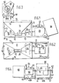
- the hopper portion of the machine comprises a frame 10 with a hopper 11 mounted thereon.
- the frame 10 is rectangular, and carries uprights 13 which support the top edge 14 of the hopper.
- the hopper 11 is formed of four major sloping plates which form a funnel shape, with three further small plates forming a well 12 at its base.
- the top edge 14 of the hopper is in the form of a band forming an upright rim to the hopper.
- the pump motor 20 is mounted on the frame 10 .
- This may be a diesel motor or an electric motor, but it is preferably an air motor, driven from a compressed air supply which is coupled to it via a coupling 23. This is convenient because a compressed air supply is required anyway for the spraying.
- the air supply is fed to the motor 20 through a control valve 21, which is controlled by a control line 22.
- the motor output is coupled through reduction gearing 24 to a shaft 25, which passes through the well 12 at the base of the hopper 11.
- This shaft 25 passes longitudinally through the well (with a coupling which is accessible in the well) to a pump 26 fixed to the well 12 and having a coupling 27 at its outer end.
- the pump 26 may be of any convenient type; preferably it is a worm and stator type, in which the shaft 25 drives a metal worm (somewhat resembling a spiral carved leg of a certain style of furniture) which passes through a rubber stator having helical grooves, of the same sense but of tighter pitch, formed on its inside.
- the coupling 27 has a flexible pipe (not shown) fixed to it in use, with the other end of the pipe ending in a nozzle at which an air supply is injected so that the operator can spray a mixture of air and the material being pumped from the hopper 11.
- the nozzle also has a control handle which is coupled to the other end of the control line 22 to the control valve 21, so that the operator can turn the pump motor 20 on and off.
- the control line 22 may be either pneumatic or a flexible mechanical cable.
- the well 12 to which the hopper 11 narrows at its base has a large area, and that the pump 26 is fed from a point slightly above the bottom of the well. This results in a good uninterrupted flow of the material through the pump, resulting in fast and relatively uniform spraying. In some previous machines, a narrow throat has been used, resulting in slow and interrupted feeding of the material to be sprayed.
- the motor 20 with the control valve 21 is normally covered by a hinged cover 30, shown in the open position in Figure 1.
- the frame 10 has feet 31 at one end and wheels 32 at the other so that it can easily be moved about.
- FIGs 3 and 4 show the second frame with the mixing motor and hopper.
- the second frame 40 comprises a rectangular portion 40A with an extension 40B to the left as seen in Figure 4.
- the portion 40A fits- inside the rim 14 of the hopper 11, and isprovided with holes 41 which match with holes 15 in the rim 14.
- the frame 40 is shown in Figure 3 vertically above the position which it occupies when bolted to the hopper as shown in Figure 1.
- the frame 40 carries a pair of supports 43 and 44 through which a shaft 51 passes, the shaft 51 being driven by a mixer motor 50 fixed to the frame 40.
- the motor 50 may be a diesel or electric motor, but is preferably an air motor (line motor 20) with a control valve 52, a coupling 53, and a control line 54. It is not usually necessary to control the motor 50 from the spray nozzle (not shown), because mixing is a batch operation which is carried out separately from the spraying.
- the shaft 51 passes through a mixer chamber 60, into which the materials to be sprayed (e.g. cement and water) are put for mixing.
- the shaft 51 carries mixing paddles 55.
- the mixing chamber 60 at the right-hand end of the mixing chamber 60, as seen in Figure 4, there is a shaft 61 fixed to the chamber 60 and having a tipping wheel 62 fixed to its other end.
- the chamber 60 is obviously normally held at or near the upright position, as shown, for mixing, and when mixing is complete, it is tipped over by means of the wheel 62 to tip the mixed material into the hopper 11.
- the frame 40 also carries wheels 65 at the motor end, so that it can be moved easily when it is dismounted from the hopper 11, and a cover 66 (shown in the open position) for the motor 50.
Landscapes
- Engineering & Computer Science (AREA)
- Architecture (AREA)
- Structural Engineering (AREA)
- Mechanical Engineering (AREA)
- Civil Engineering (AREA)
- Nozzles (AREA)
Applications Claiming Priority (2)
| Application Number | Priority Date | Filing Date | Title |
|---|---|---|---|
| GB08402867A GB2153797B (en) | 1984-02-03 | 1984-02-03 | Spraying machinery |
| GB8402867 | 1984-02-03 |
Publications (2)
| Publication Number | Publication Date |
|---|---|
| EP0153071A2 true EP0153071A2 (de) | 1985-08-28 |
| EP0153071A3 EP0153071A3 (de) | 1986-05-14 |
Family
ID=10556015
Family Applications (1)
| Application Number | Title | Priority Date | Filing Date |
|---|---|---|---|
| EP85300731A Withdrawn EP0153071A3 (de) | 1984-02-03 | 1985-02-04 | Spritzmaschine |
Country Status (2)
| Country | Link |
|---|---|
| EP (1) | EP0153071A3 (de) |
| GB (1) | GB2153797B (de) |
Cited By (2)
| Publication number | Priority date | Publication date | Assignee | Title |
|---|---|---|---|---|
| EP0300342A3 (en) * | 1987-07-24 | 1990-11-07 | P.F.T. Putz- Und Fordertechnik Gmbh | Device for continuously mixing mortar with water and for transporting this mixture by pumping |
| CN114046019A (zh) * | 2021-10-21 | 2022-02-15 | 海腾创建(深圳)集团有限公司 | 一种室内装修工程泥水施工的智能机器人 |
Families Citing this family (2)
| Publication number | Priority date | Publication date | Assignee | Title |
|---|---|---|---|---|
| GB8503370D0 (en) * | 1985-02-09 | 1985-03-13 | Doherty P D | Supply of building materials |
| GB8701227D0 (en) * | 1987-01-21 | 1987-02-25 | Jones A L | Spraying machinery |
Family Cites Families (9)
| Publication number | Priority date | Publication date | Assignee | Title |
|---|---|---|---|---|
| US951754A (en) * | 1909-01-25 | 1910-03-08 | Josiah William Buzzell | Method of handling plastic material. |
| GB587118A (en) * | 1944-01-11 | 1947-04-15 | Westberg Company | A machine for mixing and applying comminuted materials such as cementitious material or sand |
| GB969697A (en) * | 1962-07-18 | 1964-09-16 | Press W & Son Ltd | Pipe lining machine |
| US3173663A (en) * | 1963-06-03 | 1965-03-16 | Monolith Portland Cement Compa | Material movement |
| US3464676A (en) * | 1967-10-09 | 1969-09-02 | Lewis Cox | Mixer-distributor for dry cementitous material |
| US3907170A (en) * | 1970-08-20 | 1975-09-23 | Ivan Vasilievich Schedrin | Machine for application of powderlike material onto lining or surface of structure |
| IT1079502B (it) * | 1975-05-27 | 1985-05-13 | Mathis Fertigputz | Dispositivo per la fabbricazione continua di matla impasata |
| GB1603636A (en) * | 1978-05-30 | 1981-11-25 | Pyrok Surface Treatments Ltd | Spraying apparatus |
| DE3100443A1 (de) * | 1981-01-09 | 1982-08-12 | Dietrich Dipl.-Ing. 6240 Königstein Maurer | Verfahren und vorrichtung zur herstellung und gegebenenfalls foerderung von aufgeschaeumten gemischen aus bindemitteln oder bindemitteln mit zuschlagstoffen |
-
1984
- 1984-02-03 GB GB08402867A patent/GB2153797B/en not_active Expired
-
1985
- 1985-02-04 EP EP85300731A patent/EP0153071A3/de not_active Withdrawn
Cited By (2)
| Publication number | Priority date | Publication date | Assignee | Title |
|---|---|---|---|---|
| EP0300342A3 (en) * | 1987-07-24 | 1990-11-07 | P.F.T. Putz- Und Fordertechnik Gmbh | Device for continuously mixing mortar with water and for transporting this mixture by pumping |
| CN114046019A (zh) * | 2021-10-21 | 2022-02-15 | 海腾创建(深圳)集团有限公司 | 一种室内装修工程泥水施工的智能机器人 |
Also Published As
| Publication number | Publication date |
|---|---|
| GB8402867D0 (en) | 1984-03-07 |
| GB2153797A (en) | 1985-08-29 |
| EP0153071A3 (de) | 1986-05-14 |
| GB2153797B (en) | 1987-05-28 |
Similar Documents
| Publication | Publication Date | Title |
|---|---|---|
| US3885774A (en) | Apparatus for preparing and dispensing mixtures of concrete and fibres | |
| CA1182446A (en) | Vertical and horizontal auger circulating sets operating portable feed grinder mixers | |
| US5647696A (en) | Loose material combining and depositing apparatus | |
| US5314100A (en) | Grout delivery system | |
| CN111001350A (zh) | 防粉尘搅拌均匀的全自动类岩石试样搅拌机及搅拌方法 | |
| EP0153071A2 (de) | Spritzmaschine | |
| JPS61111561U (de) | ||
| GB926690A (en) | Improvements in or relating to concrete mixers | |
| US4367064A (en) | Machine for the production of home-made pasta and dough | |
| ES8201671A1 (es) | Perfeccionamientos en los dispositivos para la elaboracion einyeccion de mortero de enlucido | |
| WO2020161589A1 (en) | A mobile cement processing machine | |
| CN213221710U (zh) | 一种用于中药加工的混合设备 | |
| US3268214A (en) | Combined mixer and conveyor units | |
| CN113317179A (zh) | 一种用于园林绿化的喷灌装置 | |
| US2858116A (en) | Mixing and dispersing apparatus | |
| US3684188A (en) | Insulation applicator and method | |
| US3669418A (en) | Method of spraying concrete | |
| US2608393A (en) | Apparatus for mixing or agitating coating and granular materials | |
| US2806678A (en) | Blender | |
| CN211755683U (zh) | 一种农产品颗粒破碎装置 | |
| GB2202163A (en) | Spraying machine | |
| CN215139404U (zh) | 一种粉碎混合机 | |
| CN209093338U (zh) | 一种全自动配料装置 | |
| CN220807934U (zh) | 一种混凝士配料机 | |
| DE2349950A1 (de) | Verfahren und vorrichtung zum herstellen und verspritzen einer gebrauchsfertigen moertelmasse |
Legal Events
| Date | Code | Title | Description |
|---|---|---|---|
| PUAI | Public reference made under article 153(3) epc to a published international application that has entered the european phase |
Free format text: ORIGINAL CODE: 0009012 |
|
| AK | Designated contracting states |
Designated state(s): AT BE CH DE FR GB IT LI LU NL SE |
|
| PUAL | Search report despatched |
Free format text: ORIGINAL CODE: 0009013 |
|
| AK | Designated contracting states |
Kind code of ref document: A3 Designated state(s): AT BE CH DE FR GB IT LI LU NL SE |
|
| STAA | Information on the status of an ep patent application or granted ep patent |
Free format text: STATUS: THE APPLICATION IS DEEMED TO BE WITHDRAWN |
|
| 18D | Application deemed to be withdrawn |
Effective date: 19861117 |