EP0152679A1 - Rinneninduktionsöfen - Google Patents
Rinneninduktionsöfen Download PDFInfo
- Publication number
- EP0152679A1 EP0152679A1 EP84307617A EP84307617A EP0152679A1 EP 0152679 A1 EP0152679 A1 EP 0152679A1 EP 84307617 A EP84307617 A EP 84307617A EP 84307617 A EP84307617 A EP 84307617A EP 0152679 A1 EP0152679 A1 EP 0152679A1
- Authority
- EP
- European Patent Office
- Prior art keywords
- channel
- wall
- metal
- coil
- induction furnace
- Prior art date
- Legal status (The legal status is an assumption and is not a legal conclusion. Google has not performed a legal analysis and makes no representation as to the accuracy of the status listed.)
- Granted
Links
- 230000006698 induction Effects 0.000 title claims abstract description 29
- 229910052751 metal Inorganic materials 0.000 claims abstract description 54
- 239000002184 metal Substances 0.000 claims abstract description 54
- 230000003068 static effect Effects 0.000 claims abstract description 30
- 238000002844 melting Methods 0.000 claims abstract description 13
- 230000008018 melting Effects 0.000 claims abstract description 13
- 230000005291 magnetic effect Effects 0.000 claims abstract description 6
- 230000035515 penetration Effects 0.000 claims description 14
- 239000004411 aluminium Substances 0.000 claims description 11
- 229910052782 aluminium Inorganic materials 0.000 claims description 11
- XAGFODPZIPBFFR-UHFFFAOYSA-N aluminium Chemical compound [Al] XAGFODPZIPBFFR-UHFFFAOYSA-N 0.000 claims description 11
- 239000000470 constituent Substances 0.000 claims description 4
- 229910052739 hydrogen Inorganic materials 0.000 claims description 4
- 239000001257 hydrogen Substances 0.000 claims description 4
- RYGMFSIKBFXOCR-UHFFFAOYSA-N Copper Chemical compound [Cu] RYGMFSIKBFXOCR-UHFFFAOYSA-N 0.000 claims description 3
- UFHFLCQGNIYNRP-UHFFFAOYSA-N Hydrogen Chemical compound [H][H] UFHFLCQGNIYNRP-UHFFFAOYSA-N 0.000 claims description 3
- 229910052802 copper Inorganic materials 0.000 claims description 3
- 239000010949 copper Substances 0.000 claims description 3
- 238000007493 shaping process Methods 0.000 claims description 3
- 238000005275 alloying Methods 0.000 claims description 2
- 230000005294 ferromagnetic effect Effects 0.000 claims description 2
- 150000002739 metals Chemical class 0.000 abstract description 6
- XEEYBQQBJWHFJM-UHFFFAOYSA-N Iron Chemical group [Fe] XEEYBQQBJWHFJM-UHFFFAOYSA-N 0.000 abstract description 3
- 230000000694 effects Effects 0.000 description 7
- 230000007423 decrease Effects 0.000 description 3
- 229910001338 liquidmetal Inorganic materials 0.000 description 2
- 238000004364 calculation method Methods 0.000 description 1
- 239000003990 capacitor Substances 0.000 description 1
- 239000004020 conductor Substances 0.000 description 1
- 230000008602 contraction Effects 0.000 description 1
- 230000003628 erosive effect Effects 0.000 description 1
- 230000005484 gravity Effects 0.000 description 1
- 150000002431 hydrogen Chemical class 0.000 description 1
- 230000003993 interaction Effects 0.000 description 1
- 238000013178 mathematical model Methods 0.000 description 1
- 238000005259 measurement Methods 0.000 description 1
- 238000000034 method Methods 0.000 description 1
- 230000003134 recirculating effect Effects 0.000 description 1
- 230000003252 repetitive effect Effects 0.000 description 1
- 239000007787 solid Substances 0.000 description 1
Images


Classifications
-
- H—ELECTRICITY
- H05—ELECTRIC TECHNIQUES NOT OTHERWISE PROVIDED FOR
- H05B—ELECTRIC HEATING; ELECTRIC LIGHT SOURCES NOT OTHERWISE PROVIDED FOR; CIRCUIT ARRANGEMENTS FOR ELECTRIC LIGHT SOURCES, IN GENERAL
- H05B6/00—Heating by electric, magnetic or electromagnetic fields
- H05B6/02—Induction heating
- H05B6/16—Furnaces having endless cores
- H05B6/20—Furnaces having endless cores having melting channel only
Definitions
- This invention relates to channel induction furnaces such as are used for melting metals.
- the invention applies to furnaces for melting all types of metals but is particularly applicable to metals having high electrical conductivity such as aluminium and copper.
- high current densities are required to produce a high power input. If the channel cross sectional dimensions are comparable with the depth of penetration of the induced current then the interaction of this current with the net magnetic induction produces electromagnetic forces directed away from the walls of the channel. This squeezing action on the metal, which is referred to as an electromagnetic pinch, produces an increase in static pressure towards the centre of the channel relative to that at the wall. If the current density is not too high, this increase in static pressure is balanced by the static head of the molten metal above the channel.
- the pinch effect and the limitations it imposes on power input are well known to those familiar with channel induction furnaces. It is also known that the pinching effect can be avoided by making the radial width, W, of the channel considerably greater than the depth 9 of penetration of the induced current.
- the radial width, W is measured radially outward from the axis of the induction coil in the plane at right angles to the coil axis and in a direction normal to the axis of the channel at the point of measurement.
- cavitation phenomena (described in more detail below) will occur for sufficiently high current densities.
- the present invention is directed more particularly to improvements in the design of channels having large radial widths so as to maximise the power input per unit length that can be obtained without cavitation occurring.
- FIG. 1 shows a diagrammatic sectional view through the axis of a coil 1, around which there is a channel 2. For clarity, other parts of the furnace, such as the iron core passing through the coil, are not shown. Electromagnetic forces acting on the metal are represented by arrows the length and direction of which represent the magnitude and direction respectively of the time average forces.
- the distribution shown is that for a radial channel width, W, of several penetration depths. The forces are greatest at the inner wall nearest the coil and decay to low values over a radial distance of 2 or 3 penetration depths from this wall.
- a force distribution such as this produces a recirculating flow in the plane of Figure 1 and reduces the static pressure at the inner wall 10 (that is the wall nearest the coil) below that at the outer wall 11 of the channel 2.
- the electromagnetic forces responsible for this pressure distribution are always directed radially outwards from the coil but fluctuate from zero to a maximum value at twice the frequency of the induced current.
- the pressure at the inner wall 10 therefore fluctuates from that corresponding to the static head of liquid metal above the channel to a lower value depending on the magnitude of the electromagnetic forces. For some value of these forces, the minimum wall pressure will be less than the vapour pressure of the most volatile species in the molten metal.
- a vapour filled cavity grows on the inner wall as the electromagnetic forces increase. The cavity will immediately collapse when the electromagnetic forces decrease half a cycle later.
- the present invention shows how to obtain the maximum power per unit length without cavitation occurring.
- the electromagnetic force is equal to the vector product of the current density and the magnetic induction.
- the obvious way to reduce these forces is to reduce the current density by increasing the cross sectional area of the current carrying part of the channel.
- Electromagnetic theory shows that practically all the current flows through the region within two penetration depths of the inner wall. Consequently, increasing the already large radial width W will have only a minor effect on the current density distribution. In these circumstances the current density is controlled primarily by the axial width, L, of the channel, that is the width measured parallel to the coil axis (see Figure 1).
- this axial width is less than about two penetration depths, then for a given total channel current, the current density varies almost inversely as the channel axial width. For axial widths, greater than about two penetration depths, there are large variations in current density with axial position in the channel.
- the current tensity is a minimum on the mid plane (A-A in Figure 1) and increases to a maximum at each side wall 12 of the channel.
- Maximum current densities therefore occur in the two corners B nearest to the induction coil 1.
- the wall is shaped to follow a contour of constant current density or constant static pressure. This effectively eliminates the corner regions where the current density would have been too high. Shaping the inner wall causes some adjustment of the current density on the mid plane but successive approximations rapidly converge to a satisfactory choice of axial width L and cross section shape. The current density distribution then obtained produces the maximum power per unit length for the specified total channel current, while avoiding cavitation at the inner wall.
- the channel wall nearest the induction coil is shaped to follow a contour of constant current density or to follow a contour of constant static pressure.
- the current density distribution in the channel may be controlled by the combination of selecting the axial width of the channel and shaping the wall of the channel nearest the induction coil, such that at the maximum power rating for the channel, the minimum static pressure at the shaped wall is greater than the vapour pressure of the most volatile species in the molten metal.
- the present invention enables the channel section to be optimised for maximum power input per unit length of channel and with a selected static pressure which can be chosen to prevent the cavitation problems discussed above.
- said shaped wall may be so shaped that the static pressure on said shaped wall is greater than the vapour pressure of the most volatile constituent.
- the static pressure on said wall is the result of all the forces acting on the metal, the most important of which are electromagnetic and gravitational forces and, to a lesser extent, inertial forces arising from the motion of the metal.
- said shaped wall may be so shaped that the static pressure on said shaped wall is greater than the vapour pressure of hydrogen in solution in the aluminium.
- said shaped wall may be so shaped that the static pressure on said shaped wall is greater than the vapour pressure of any volatile alloying metal species.
- Optimisation of the axial width and cross sectional shape of the channel may be carried out using a mathematicalmodel of the furnace. Computations may be made on a computer to obtain the current density distribution, electromagnetic forces and power density distribution. Using the calculated electromagnetic forces, an estimate may then be made of the static pressure at the inner wall on the mid plane of the channel. The minimum value of this pressure may be chosen to be always at least 0.1 bar and preferably 0.2 bar greater than the vapour pressure of the most volatile species present in the molten metal. If the minimum static pressure at the wall is too low or significantly higher than this critical value, the axial width of the channel is adjusted and the calculation repeated. Strictly the inner wall of the channel should be shaped to make the static pressure constant along the wall in the axial direction of the channel.
- the axial width and the shape of the wall nearest the coil are preferably selected such that the minimum static pressure along the shaped wall is at least 0.1 bar greater than the vapour pressure of the most volatile species present in the molten metal.
- the axial width of the channel is preferably in the range of 4 to 6 penetration depths for the current in the molten metal at the energising frequency.
- the radial width of the channel is preferably in the range of 3 to 5 penetration depths for the current in the molten metal at the energising frequency.
- the channel induction furnace has an induction coil 1 around which is maintained a loop of molten metal.
- the channel 2 constituting this loop of molten metal is connected to a bath 3 of molten metal, located above the loop.
- the molten metal is contained in a refractory lined vessel 4.
- a laminated iron core 5 passes through the coil 1 and forms a closed magnetic circuit linked with the coil 1 and channel 2.
- This heat is conveyed to the metal in the bath 3 above by conduction and by mixing of metal between the loop and bath.
- Solid metal is melted by adding it to the molten bath which is maintained significantly above the melting temperature. Periodically molten metal is removed from the bath typically by tilting the furnace so that the metal can be poured out.
- This particular furnace is for melting aluminium and the primary cause of cavitation is the presence of dissolved hydrogen in the molten aluminium.
- the vapour pressure of this hydrogen which is considered in designing the shape of the channel to maximise power input whilst preventing cavitation.
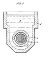
- Figure 3 shows the cross sectional shape of a channel designed for a maximum power input of 150 kW per metre length in pure aluminium for an energising frequency of 50 Hz.
- the penetration depth, ⁇ , at this frequency is 32 mm and the axial width in this particular embodiment is 5.78 while the radial width is 3.8 ⁇ .
- the inner wall 10 is shaped to follow a contour of constant current density. These dimensions lie within a preferred range of 4 ⁇ to 6 ⁇ for the axial width and 3; to 5 ⁇ for the radial width.
- the power factor of the furnace decreases with increasing axial width and the preferred range 4 ⁇ to 6 ⁇ represents a balance between the need to maximise power per unit length and to minimise the cost of compensating capacitors.
- the circumferential length of the channel must be sufficient to generate the required power input for the furnace.
- the technique described above enables this power input to be achieved in the smallest diameter loop for which cavitation can be avoided, and hence represents a compact and cost effective design.
- multi-loop designs can be more cost effective than a single large diameter loop and the invention also encompasses such designs in which each loop has an optimum cross sectional shape and size.
Landscapes
- Physics & Mathematics (AREA)
- Electromagnetism (AREA)
- Furnace Details (AREA)
- Crucibles And Fluidized-Bed Furnaces (AREA)
- General Induction Heating (AREA)
Applications Claiming Priority (2)
| Application Number | Priority Date | Filing Date | Title |
|---|---|---|---|
| GB08404568A GB2154840B (en) | 1984-02-21 | 1984-02-21 | Channel induction furnaces |
| GB8404568 | 1984-02-21 |
Publications (2)
| Publication Number | Publication Date |
|---|---|
| EP0152679A1 true EP0152679A1 (de) | 1985-08-28 |
| EP0152679B1 EP0152679B1 (de) | 1989-04-19 |
Family
ID=10556974
Family Applications (1)
| Application Number | Title | Priority Date | Filing Date |
|---|---|---|---|
| EP84307617A Expired EP0152679B1 (de) | 1984-02-21 | 1984-11-05 | Rinneninduktionsöfen |
Country Status (4)
| Country | Link |
|---|---|
| US (1) | US4611338A (de) |
| EP (1) | EP0152679B1 (de) |
| DE (1) | DE3477867D1 (de) |
| GB (1) | GB2154840B (de) |
Cited By (1)
| Publication number | Priority date | Publication date | Assignee | Title |
|---|---|---|---|---|
| WO2014134679A1 (en) * | 2013-03-07 | 2014-09-12 | Bluescope Steel Limited | Channel inductor |
Families Citing this family (2)
| Publication number | Priority date | Publication date | Assignee | Title |
|---|---|---|---|---|
| SE511892C2 (sv) * | 1997-06-18 | 1999-12-13 | Abb Ab | Ränninduktor och smältugn innefattande sådan ränninduktor |
| KR101213559B1 (ko) * | 2004-12-22 | 2012-12-18 | 겐조 다카하시 | 교반장치 및 방법과, 그 교반장치를 이용한 교반장치 부착용해로 |
Citations (2)
| Publication number | Priority date | Publication date | Assignee | Title |
|---|---|---|---|---|
| FR1359528A (fr) * | 1963-05-31 | 1964-04-24 | Ingenior Gunnar Schjelderup In | Four électrique à induction à canal |
| EP0077750A1 (de) * | 1981-10-20 | 1983-04-27 | Asea Ab | Rinnenofen |
-
1984
- 1984-02-21 GB GB08404568A patent/GB2154840B/en not_active Expired
- 1984-09-11 US US06/649,335 patent/US4611338A/en not_active Expired - Fee Related
- 1984-11-05 DE DE8484307617T patent/DE3477867D1/de not_active Expired
- 1984-11-05 EP EP84307617A patent/EP0152679B1/de not_active Expired
Patent Citations (2)
| Publication number | Priority date | Publication date | Assignee | Title |
|---|---|---|---|---|
| FR1359528A (fr) * | 1963-05-31 | 1964-04-24 | Ingenior Gunnar Schjelderup In | Four électrique à induction à canal |
| EP0077750A1 (de) * | 1981-10-20 | 1983-04-27 | Asea Ab | Rinnenofen |
Cited By (4)
| Publication number | Priority date | Publication date | Assignee | Title |
|---|---|---|---|---|
| WO2014134679A1 (en) * | 2013-03-07 | 2014-09-12 | Bluescope Steel Limited | Channel inductor |
| CN105143803A (zh) * | 2013-03-07 | 2015-12-09 | 蓝野钢铁有限公司 | 槽式感应器 |
| US9989312B2 (en) | 2013-03-07 | 2018-06-05 | Bluescope Steel Limited | Channel inductor |
| CN105143803B (zh) * | 2013-03-07 | 2019-04-26 | 蓝野钢铁有限公司 | 槽式感应器 |
Also Published As
| Publication number | Publication date |
|---|---|
| GB8404568D0 (en) | 1984-03-28 |
| US4611338A (en) | 1986-09-09 |
| EP0152679B1 (de) | 1989-04-19 |
| DE3477867D1 (en) | 1989-05-24 |
| GB2154840B (en) | 1986-11-12 |
| GB2154840A (en) | 1985-09-11 |
Similar Documents
| Publication | Publication Date | Title |
|---|---|---|
| US7848383B2 (en) | Cold crucible induction furnace with eddy current damping | |
| US5109389A (en) | Apparatus for generating an inductive heating field which interacts with metallic stock in a crucible | |
| EP1233244B1 (de) | Induktionsofen und Bodenabstichmechanismus | |
| CA1074854A (en) | Electromagnetic apparatus for constriction of liquid metals | |
| US4821284A (en) | Scrap-melting process and electric furnace for carrying out the process | |
| JPS6254579B2 (de) | ||
| US3223519A (en) | Induction furnace | |
| KR100536174B1 (ko) | 전자기장을 이용한 금속의 수직 연속 주조 방법 및 이를 위한 주조 장치 | |
| EP0152679B1 (de) | Rinneninduktionsöfen | |
| EP0248242B1 (de) | Stranggiessanlage | |
| KR19990076501A (ko) | 강철스트립의 용융도금코팅 시스템 | |
| Sagardia et al. | Electromagnetic levitation melting of large conduction loads | |
| US2970830A (en) | Varying the falling speed of a stream of molten metal | |
| JPS608899B2 (ja) | 電磁連続鋳造鋳型 | |
| US4143997A (en) | Electromagnetic induction pump for molten metal including impurities | |
| US3210811A (en) | Apparatus for controlling the rate of feed of the melt of continuous casting plant | |
| EP0048629B1 (de) | Rinneninduktionsöfen | |
| US3751572A (en) | Plant for the electroslag remelting of metal | |
| US4458353A (en) | Channel-type induction furnace | |
| GB2041803A (en) | Electromagnetic casting apparatus and process | |
| US4570699A (en) | Multi-turn coils of controlled pitch for electromagnetic casting | |
| US4518030A (en) | Multi-turn coils of controlled pitch for electromagnetic casting | |
| EP0916434A1 (de) | Elektromagnetische Kontrolle des Meniskus beim Stranggiessen | |
| GB2312861A (en) | Valves in continuous casting | |
| US4516627A (en) | Multi-turn coils of controlled pitch for electromagnetic casting |
Legal Events
| Date | Code | Title | Description |
|---|---|---|---|
| PUAI | Public reference made under article 153(3) epc to a published international application that has entered the european phase |
Free format text: ORIGINAL CODE: 0009012 |
|
| AK | Designated contracting states |
Designated state(s): BE DE FR IT SE |
|
| 17P | Request for examination filed |
Effective date: 19851010 |
|
| 17Q | First examination report despatched |
Effective date: 19870224 |
|
| ITF | It: translation for a ep patent filed | ||
| GRAA | (expected) grant |
Free format text: ORIGINAL CODE: 0009210 |
|
| AK | Designated contracting states |
Kind code of ref document: B1 Designated state(s): BE DE FR IT SE |
|
| REF | Corresponds to: |
Ref document number: 3477867 Country of ref document: DE Date of ref document: 19890524 |
|
| ET | Fr: translation filed | ||
| PLBE | No opposition filed within time limit |
Free format text: ORIGINAL CODE: 0009261 |
|
| STAA | Information on the status of an ep patent application or granted ep patent |
Free format text: STATUS: NO OPPOSITION FILED WITHIN TIME LIMIT |
|
| 26N | No opposition filed | ||
| ITTA | It: last paid annual fee | ||
| PGFP | Annual fee paid to national office [announced via postgrant information from national office to epo] |
Ref country code: FR Payment date: 19911025 Year of fee payment: 8 |
|
| PGFP | Annual fee paid to national office [announced via postgrant information from national office to epo] |
Ref country code: SE Payment date: 19911112 Year of fee payment: 8 |
|
| PGFP | Annual fee paid to national office [announced via postgrant information from national office to epo] |
Ref country code: BE Payment date: 19911113 Year of fee payment: 8 |
|
| PGFP | Annual fee paid to national office [announced via postgrant information from national office to epo] |
Ref country code: DE Payment date: 19911210 Year of fee payment: 8 |
|
| PG25 | Lapsed in a contracting state [announced via postgrant information from national office to epo] |
Ref country code: SE Effective date: 19921106 |
|
| PG25 | Lapsed in a contracting state [announced via postgrant information from national office to epo] |
Ref country code: BE Effective date: 19921130 |
|
| BERE | Be: lapsed |
Owner name: THE ELECTRICITY COUNCIL Effective date: 19921130 |
|
| PG25 | Lapsed in a contracting state [announced via postgrant information from national office to epo] |
Ref country code: FR Effective date: 19930730 |
|
| PG25 | Lapsed in a contracting state [announced via postgrant information from national office to epo] |
Ref country code: DE Effective date: 19930803 |
|
| REG | Reference to a national code |
Ref country code: FR Ref legal event code: ST |
|
| EUG | Se: european patent has lapsed |
Ref document number: 84307617.5 Effective date: 19930610 |