EP0152640A2 - Membrandistanzplatte und alternierend bewegender Dialysator - Google Patents
Membrandistanzplatte und alternierend bewegender Dialysator Download PDFInfo
- Publication number
- EP0152640A2 EP0152640A2 EP84201368A EP84201368A EP0152640A2 EP 0152640 A2 EP0152640 A2 EP 0152640A2 EP 84201368 A EP84201368 A EP 84201368A EP 84201368 A EP84201368 A EP 84201368A EP 0152640 A2 EP0152640 A2 EP 0152640A2
- Authority
- EP
- European Patent Office
- Prior art keywords
- blood
- dialyzer
- membrane
- membranes
- flow
- Prior art date
- Legal status (The legal status is an assumption and is not a legal conclusion. Google has not performed a legal analysis and makes no representation as to the accuracy of the status listed.)
- Withdrawn
Links
Images


Classifications
-
- B—PERFORMING OPERATIONS; TRANSPORTING
- B01—PHYSICAL OR CHEMICAL PROCESSES OR APPARATUS IN GENERAL
- B01D—SEPARATION
- B01D61/00—Processes of separation using semi-permeable membranes, e.g. dialysis, osmosis or ultrafiltration; Apparatus, accessories or auxiliary operations specially adapted therefor
- B01D61/24—Dialysis ; Membrane extraction
- B01D61/28—Apparatus therefor
-
- A—HUMAN NECESSITIES
- A61—MEDICAL OR VETERINARY SCIENCE; HYGIENE
- A61M—DEVICES FOR INTRODUCING MEDIA INTO, OR ONTO, THE BODY; DEVICES FOR TRANSDUCING BODY MEDIA OR FOR TAKING MEDIA FROM THE BODY; DEVICES FOR PRODUCING OR ENDING SLEEP OR STUPOR
- A61M1/00—Suction or pumping devices for medical purposes; Devices for carrying-off, for treatment of, or for carrying-over, body-liquids; Drainage systems
- A61M1/14—Dialysis systems; Artificial kidneys; Blood oxygenators ; Reciprocating systems for treatment of body fluids, e.g. single needle systems for hemofiltration or pheresis
- A61M1/16—Dialysis systems; Artificial kidneys; Blood oxygenators ; Reciprocating systems for treatment of body fluids, e.g. single needle systems for hemofiltration or pheresis with membranes
- A61M1/26—Dialysis systems; Artificial kidneys; Blood oxygenators ; Reciprocating systems for treatment of body fluids, e.g. single needle systems for hemofiltration or pheresis with membranes and internal elements which are moving
- A61M1/267—Dialysis systems; Artificial kidneys; Blood oxygenators ; Reciprocating systems for treatment of body fluids, e.g. single needle systems for hemofiltration or pheresis with membranes and internal elements which are moving used for pumping
-
- B—PERFORMING OPERATIONS; TRANSPORTING
- B01—PHYSICAL OR CHEMICAL PROCESSES OR APPARATUS IN GENERAL
- B01D—SEPARATION
- B01D63/00—Apparatus in general for separation processes using semi-permeable membranes
- B01D63/08—Flat membrane modules
- B01D63/082—Flat membrane modules comprising a stack of flat membranes
- B01D63/084—Flat membrane modules comprising a stack of flat membranes at least one flow duct intersecting the membranes
-
- A—HUMAN NECESSITIES
- A61—MEDICAL OR VETERINARY SCIENCE; HYGIENE
- A61M—DEVICES FOR INTRODUCING MEDIA INTO, OR ONTO, THE BODY; DEVICES FOR TRANSDUCING BODY MEDIA OR FOR TAKING MEDIA FROM THE BODY; DEVICES FOR PRODUCING OR ENDING SLEEP OR STUPOR
- A61M1/00—Suction or pumping devices for medical purposes; Devices for carrying-off, for treatment of, or for carrying-over, body-liquids; Drainage systems
- A61M1/14—Dialysis systems; Artificial kidneys; Blood oxygenators ; Reciprocating systems for treatment of body fluids, e.g. single needle systems for hemofiltration or pheresis
- A61M1/16—Dialysis systems; Artificial kidneys; Blood oxygenators ; Reciprocating systems for treatment of body fluids, e.g. single needle systems for hemofiltration or pheresis with membranes
- A61M1/26—Dialysis systems; Artificial kidneys; Blood oxygenators ; Reciprocating systems for treatment of body fluids, e.g. single needle systems for hemofiltration or pheresis with membranes and internal elements which are moving
Definitions
- This invention concerns dialyzer apparatus for use as an extracorporeal mass transfer device or artificial kidney, and more particularly, is directed to a membrane spacer element for a reciprocating dialyzer apparatus and to dialyzer apparatus incorporating such spacing elements to enhance operation of the unit.
- the invention concerns improvements in spacer elements for membrane means of a blood treatment unit that receives blood at one side of said membrane means and treating solution at the other side of said membrane means, and having a substantially flat peripheral portion.
- Dialysis apparati are well known, and it is likewise well known that an essential feature of such an apparatus is the dialyzer unit in.which the blood to be treated is brought into contact with one face of a semi-permeable membrane while the other face is brought into contact with a dialysate.
- dialyzers now known or utilized are of the so-called "flow-through” type wherein blood is introduced into the treatment area through one conduit and, after treatment, discharged from the unit through a separate conduit.
- the blood is commonly withdrawn from the patient through an artery or arterialized vein with the treated blood being then pumped back into the patient through a vein.
- a reciprocating dialyzer wherein the blood is introduced into the blood treatment area and then discharged, after treatment, through the same conduit as utilized for introduction of the blood into the blood treatment area.
- a dialyzer is shown in U.S. Patent No. 4,071,444, wherein the blood is introduced into the blood treatment area, formed by a pair of thin semi-permeable membranes, through a central opening with dialysate being introduced into the unit for membrane contact at the periphery of the unit.
- the reciprocating dialyzer may be used with a suspension of sorbent in the dialysate.
- the sorbent keeps the concentration of toxic substances low in the dialysate, and thereby facilitates mass transfer across the membranes.
- a disadvantage of the suspension is that, as a thick slurry, it is difficult to maintain in a unidirectional flow pattern through small orifices. Therefore, special attention must be made to the orifices and flow channels of any spacers or membrane limiters in the reciprocating dialyzer.
- This invention provides an improved membrane spacer element for use in a dialyzer unit for extracorporeal treatment of biologic fluid, and also a reciprocating dialyzer incorporating such spacer elements, which limit membrane displacement and cause formation of a thin column of fluid to be treated while not unduly masking the membrane surfaces and allowing flow of treatment material (which may be a sorbent suspension) next to the membranes, including those times when the chamber is filled with blood as the fluid to be treated.
- treatment material which may be a sorbent suspension
- Dialyzer units incorporating membrane spacers are described in US-A-4154792 and US-A-3396849.
- US-A-3413095 describes a circular plate-type dialyzer having a central aperture.
- a reciprocating dialyzer apparatus comprising a pair of spacer elements as defined in the immediately-preceding paragraph, and membrane means comprising a pair of membranes defining a blood chamber, each membrane having a central opening and parallel stress lines, the stress lines of the two membranes being perpendicular,
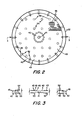
- dialyzer unit 20 is shown in figure 1 to include a membrane package 21 with spacing elements 22 at the bpposite sides thereof.
- Membrane package 21 includes a pair of thin, semi-permeable, disc-shaped membranes 24 and 25 that are coaxially positioned with respect to one another. and each has a central aperture 26 therein with the apertures being aligned with one another. Each mem- . brane has stress lines 27 therein and the stress lines of membrane 24 are oriented at an angle of 90° with respect to the stress lines of membrane 25 when in the operating position.
- Central apertures 26 are also aligned with the central aperture 28 of a gasket 29 positioned between the membranes at the central portion thereof.
- gasket 29 has a plurality of notches, or slots, 30 which open the central aperture to the treatment area, or blood chamber (where blood is the fluid to be treated), 32 (as shown in FIGURE 5) formed between the interior faces 33 of each of the membranes 24 and 25 when the membranes are sealed at the central, or hub, area 36 and at the periphery, or rim area, 37 as brought out more fully hereinafter.
- Spacing elements, or spacers, 22 are formed, as shown in FIGURES 1 through 5, by a flexible disc having a central portion 40 with a central aperture 41 therein, a rim portion 42, and a spacing, or membrane supporting, portion 43 extending between the central and rim portions.
- spacers 22 are positioned coaxially with respect to membranes 24 and 25 and the central apertures 41 of the spacers are aligned with the central apertures of gasket 29 and membranes 24 and 25 so that a single central conduit is formed therethrough to chamber 32 formed between the membranes.
- Central portion 40 and rim portion 42 of each spacer 22 is flat so as to provide central and rim sealing surfaces for the membranes.
- the rim portion 42 of each spacer 22 has a plurality of notches, or slots, 45.extending radially thereacross to provide a slurry inlet into the dialysis chamber 47 (as shown in FIGURE .5) formed between the exterior face 48 of upper membrane 24 or lower membrane 25 (depending upon which is adjacent to the spacer) and the adjacent face of spacer 22 (i.e., the upper face 49 of the lower spacer 22 as shown in FIGURE 1 and the lower face 50 of the upper spacer 22 as shown in FIGURE 1).
- a ring 51 is preferably provided at the rim of each spacer 22 so that the notches are, in essence, ports leading from the outside of the unit into the dialysate chamber. While not shown, it is to be realized that the ring could be integrally formed with the rim portion with a passage therethrough forming the ports 45 through which the slurry can flow to and from the dialysate chamber. As also shown in FIGURES 1 and 2, an aperture 52 is provided adjacent to each slot 45 in rim portion 42 to allow slurry flow (i.e., flow of the treating solution which can be a suspension of sorbents for treatment of blood as brought out hereinafter between faces 49 and 50 of spacer 22.
- slurry flow i.e., flow of the treating solution which can be a suspension of sorbents for treatment of blood as brought out hereinafter between faces 49 and 50 of spacer 22.
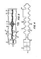
- each spacing element 22 includes, as shown in FIGURES 1 through 5, a continuous series of protuberances 53 extending upwardly from a base pad (only a few of such protuberances being shown in FIGURE 1 for illustrative purposes), it being realized that such protuberances are preferably closely spaced, uniform, and continuous as indicated by the broken area of FIGURE 2 and in the cross-sectional views of FIGURES 3 through 5 so that the tops of the protuberances provide minimal membrane contact.
- protuberances 53 may be a continuous series of protuberances having a pyramidal shape.
- the series of protuberances 53' may be a variety of tapered or pointed shapes, including a conical shape, and the conical shape is now preferred.
- a plurality of spaced columns 54 are fixed to the top face, or surface, 49 of each spacer 22, and a second plurality of columns 55, spaced from each other and spaced from lines extended normally through the spacer from columns 54 (as best shown in FIGURE 2) are fixed to the bottom face, or surface, 50 of each spacer 22.
- columns 54 and 55 are in a square array to thus provide separate spaced column supports for stacking a plurality of membrane packages and spacers in the dialyzer apparatus, aligned as indicated in FIGURE 1.
- the protuberances act as limiters to limit the displacement of the membranes, and therefore limit the maximum volume of blood that can be introduced into the blood chamber.
- Each dialyzer unit 20 is-assembled for use in a positioning, or clamping, unit 56 consisting of a base plate 57 and top plate 58 having a plurality of rods, or bolts, 59 extending therethrough as shown best in FIGURE 1.
- a plurality of units 20 are normally stacked on base plate 57 (a removable center post (not shown) can be utilized for alignment of the central apertures during stacking if desired).
- the plates are then compressed (as by tightening nuts 61 at the lower ends) to form and maintain the central and rim seals for each membrane package 21 (the seals being provided by the spacer elements 22 at each side of each membrane package as brought out hereinabove).
- Plates 57 and 58 each have a central aperture 63 therein which aperatures are aligned with the apertures on the membrane package and spacers.
- a fitting 64 with a gasket 65 thereon is provided in aperture 63 of base plate 57, and blood (or other fluid to be treated such as peritoneal dialysis fluid) is introduced through this aperture and the central conduit into the blood chamber and then withdrawn through this same conduit and blood fitting from the chamber.
- a plug 66 is provided at the top plate 58 provided at the aperture 63 in top plate 58, and washer 68 with central aperture 69 therein are provided adjacent to the base and top plates to aid in sealing.
- membranes 24 and 25 were cuprophan membranes (150 pm) having a five inch(12-7 cm) diameter with a 0.25 inch (0.64 cm) central aperture; blood gasket 29 was a 0.75 inch (1.92 cm) diameter disc of polyethylene material of 0.04 inch (0.10 cm) thickness with a 0.25 inch (0.64 cm) central aperture; spacing elements 22 were of polyethylene material having a five inch (12.7 cm) diameter with a central portion of one inch (2.54 cm) diameter and 0.02 inch (0.05 cm) thickness with a 0.25 inch (0.84 cm) diameter central aperture and a rim portion having a 0.25 inch (0.65 cm) diameter and 0.02 inch (0.05 cm) thickness; ring 51 was of polyethylene material having a 4.75 inch (12.07 cm) interior diameter and 5 inch (12.7 cm) outside diameter and a thickness of 0.02 inches (0.05 cm); gaskets 68 were 0.75 inch (1.92 cm) diameter discs of silicone rubber of 0.02 inch (
- the foregoing is meant to be illustrative of a working embodiment of the unit and the invention is not meant to be limited thereto.
- the elements of the unit could, for example, be square or rectangular, rather than round, could be of different dimensions or characteristics, as, for example, being of seven inch (17.78 cm) diameter or the membranes being more permeable (100 pm, for example), of different materials, having a different configuration of protruberances and/or columns, and/or have a different number of notches 45, such as, for example, 32 notches, all of which would be obvious to one skilled in the art.
- a plurality of membrane packages are normally stacked in a clamping unit 56 having base and top plates 57 and 58 (which are shown to be of hexagonal shape but can be circular if desired), as brought out hereinabove.
- This assemblage is then placed,for use in a reciprocal dialyzer apparatus, in a case assembly 72 as shown in Figure 6.
- case 72 includes a bottom plate 74 (which can be combined with base plate 57), a top plate 57 and cylindrical sidewalls 76, with the unit held to form a sealed enclosure by means of a plurality (six as shown) of rods, or bolts, 77 having nuts 78 thereon (with sealing gaskets being used as needed).
- This configuration can also be varied as desired for a particular use.
- Bottom plate 74 has blood fitting 64 extending therethrough and slurry port 80 is formed in sidewall 76.
- Top wall 75 also has a threaded fill hole 81 and a vent 82 (which is used to expel air from case assembly 72 and then is closed).
- the slurry is inserted into, and sealed within, the air-tight case 72 with slurry preferably entirely filling the case so that no air remains.
- the slurry is then used to pump the membrane packages (by use of a slurry pump (not shown) so that the blood moves passively as a result cf increased and decreased slurry pressures (to cause slurry compression and decompression).
- spacer element 85 is similar to spacer element 22 in providing a solid and flat outer rim portion 87 having a 0.25 inch (0.64 cm) diameter and a solid central portioh 90 except that the solid central portion is of diminished size-and terminates in a one inch diameter aperture 91.
- the central and rim portions are preferably melted by application of heat to form the solid and substantially flat portions thereat.
- the membrane-engaging portion 93 between the central . and rim portions of spacer 85 is of mesh or woven construction and preferably is a screen.
- FIG 8. An exploded side-sectional view of the dialyzer unit when utilizing spacer elements 85 is shown in figure 8. As shown, a pair of rings 95 and 96 are positioned at opposite sides of the rim portions 87 of the spacer element 85 (notches 88, as shown in figure 7, provide an input for slurry) and membranes 24 and 25 are positioned adjacent to the spacer element 85 (only one set is shown in figure 8) with blood gasket 29 therebetween in the same manner as described hereinabove with respect to blood treatment unit 20, except that an added central washer 98 is preferably utilized.
- a second spacer element 85 (not shown in figure 8) is positioned at the other side of each membrane package to thus seal the membrane between the spacer elements and thus to establish the blood chamber between the membranes and the dialysischambers outside the membrane package in the same manner as described hereinabove with respect to blood treatment unit 20.
- screen 85 includes strands 100 and 101 oriented at 60° angles with respect-to one another with strands 100 of screen 85 (of the top spacer element) contacting the top membrane 24 at an angle of 90° with respect to the stress lines of membrane 24, and with strands 101 of screen 85 (of the lower spacer element) contacting the lower membrane 25 also at an angle of 90° with respect to the stress lines of membrane 25 (the stress lines 27 of membranes 24 and 25 are.oriented with stress lines at an angle of 90° with respect to one another).
- the screen spacer element 85 allows the dialyzer unit to exert negative pressure on the dialysate side throughout the pumping cycle.
- the blood volume in the blood chamber is nearly zero until a vacuum is pulled on the slurry to open the membranes into the screen voids.
- the elastic recoil of the membrane creates enough pressure to force all or most of the blood out of the blood chamber formed by the membrane package.
- a uniform, thin blood column is also provided by use of screen spacer element 85 and this element also allows a denser slurry suspension to be utilized (up to 500 grams of solids per litre of liquid which constitutes nearly a 100% reduction in water mass and slurry volume), allows the overall flow requirements of the dialyzer apparatus to be reduced, and can reduce an ammonia problem by better mixing of the slurry.
- spacer element 85 of polyethylene having a thickness of 0.05 inches (.012 cm) at the screen portion 92 and 0.02 inches (0.05 cm) at the first rim portion 87 was utilized in lieu of spacer element 22, a 0.75 inch diameter washer 98 of cellulose acetate with a 0.01 inch (0.025 cm) thickness and a 0.25 inch (0.64 cm) diameter central aperture was utilized, and rings 95 and 96 of polyethylene with a thickness of 0.015 inches (0.031 cm) were utilized in lieu of ring 51 as used in spacer element 22.
- this is meant to be illustrative of a particular embodiment and the invention is not meant to be limited thereto.
- the blood treatment unit of this invention thus provides a free-sorbent dialyzer which utilizes spacer elements providing membrane supports that create thin packages for blood flow in the blood chamber.
- spacer elements providing membrane supports that create thin packages for blood flow in the blood chamber.
- the dialyzer apparatus uses a sorbent suspension having free access from a reservoir to the spaces between the membrane packages.
- the in vitro creatinine clearance has been found to be 75 ml/min-M 2 .
- the creatinine clearance, flow resistance, and compliance of the dialyzer have also been found to be constant during four to six hours of test.
- In vivo tests have shown that during urea and creatinine infusion in a normal dog and in a dog with 3/4 nephrectomy, the in vivo creatinine clearance agrees (within +10%) with the in vitro clearance.
- Sodium, potassium, calcium, and bicarbonate fluxes have been found to be within limits acceptable for patients in renal failure.
- the blood treatment unit of this invention allows higher clearance for urea and creatinine, and larger amounts of sorbent to be used, with construction and sterilization being simplified so that this invention allows the dialyzer apparatus to be a portable, single-needle, self-contained, solo-operated artificial kidney.
- the dialyzer unit of this invention is preferably used with a slurry that includes absorbent chemicals, to regenerate dtalysate.
- a high sorbent suspension concentration is provided, such as a suspension of about 27 wt. % of sorbent such as activated charcoal, calcium-sodium , loaded zeolites, and/or urease,. which is introduced into the dialysate chambers as the treating solution.
- sorbent such as activated charcoal, calcium-sodium , loaded zeolites, and/or urease
- the sorbents were minimally saturated, and thus relatively well mixed, during use. Dialysis of up to nine hours could be achieved with little decrease in -mass transfer coefficient.
- the sorbent suspension is allowed free access between the case assembly enclosing the blocd treatment units and the dialysate spaces, cr chambers, between the membrane packages.
- the entire apparatus can be assembled and sterilized in the absence of a sorbent suspension, and can be utilized with as large a suspension volume as needed.to prevent saturation.
- Each dialyzer unit of this invention was thus designed with an expected fill volume of three to four ml per membrane package with unimpeded flow of the sorbent suspension between the membrane and the support (during membrane package expansion and collapse), a thin, uniform blood column thickness, at full expansion of the membrane package, and minimal masking of the membrane (i.e., contact with the membrane supports) to provide continued transfer of solutes from the blood side to sorbent suspension at full membrane expansion.
- a dialyzer apparatus having dialyzer units 20 (as shown in FIGURES 1 through 5) encased in case assembly 72 (as shown in FIGURE 6) was subjected to hydraulic tests. After air testing of the apparatus and filling the dialyzer with saline, a three-way stop cock was attached to the blood inlet port of the dialyzer and a mercury manometer was then attached to one port of the stop cock. With a 60milliliter syringe, saline was injected into the dialyzer and pressure recorded up to 300 mmHG. A typical volume versus pressure (compliance) curve is shown in FIGURE 7. In repeated trials, 3.5 + 0.7 ml per membrane package could be injected before the pressure reached 300 mmHG. The compliance curve for outflow was similar to inflow, if small corrections for ultra-filtration and trapped volume are taken into account. This indicated that work performed in filling could be partially recovered in emptying of the packages.
- Alterations in pressure of the sorbent suspension was used to promote movement of blood into and out of the dialyzer apparatus, without need for a blood pump.
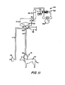
- a pressure-vacuum system 104 was used to change dialysate pressure during in vivo tests, as illustrated in FIGURE 11.
- a 250 ml graduated reservoir 106 was provided with the lower end in communication with port 80 of case assembly 72 having membrane packages 20 therein.
- the air-fluid level of reservoir 106 was approximately 40 cm al ove the blood inlet point provided at blood fitting 64.
- a pressure pump (0.5 H.P.) 108 generated positive and negative pressures ranging from -200 to +100 mm mercury in reservoir 106.
- An electric valve 109 actuated by a timer 110 controlled the cycling of positive and negative pressure with cycle times of 60 to 120 seconds being produced, with inflow-outflow ratios of approximately 3:1.
- the blood inlet 64 was attached to a silicone tube (1/8 inch I.D.) 112 and the tube was attached to an arterio-venous shunt 113 of the test animal 114.
- pressure gauge 116 was connected in communication with tube 112 through tube 117, and samples were injected into tube 112 by means of sample syringe 118 and needle 119 at three-way connector 120.
- Total volume of fluid within the case and reservoir was determined by following the location of the air-fluid interface in the 250 ml reservoir 106. Volume changes in case 72 were assumed to be due to 1) blood flow into or out of the dialyzer, 2) ultrafiltration of fluid into the dialyzer, and 3) case compliance, a 20-30 cc volume change occurring rapidly after pressure change, in the absence of blood flow into the dialyzer.
- Equation 1 is difficult to solve exactly, due to the complex relationship of P to V.
- Equation 1 it is possible to obtain a numerical approximation: The n data points obtained during blood flow tests can thus be analyzed utilizing data from the compliance tests, and graphically represented as: The resistance of the dialyzer may then be determined from the slope of this graph.
- The.fluid was injected in the following two flow modes into the membrane package through the blood inlet'port: 1) the "trapezoid” mode, in which the fluid was injected as rapidly as possible (within 5 seconds), maintained at a constant volume, and withdrawn as rapidly as possible (about 10 seconds), and 2) the "saw-tooth” mode, in which the dialyzer was filled and emptied at constant volumetric low rate and with equal inflow and outflow time segments.
- the entire effluent was collected from each cycle, mixed, and the creatinine and urea concentration measured.
- a Beckman automatic creatinine analyzer (Jafee method) was used for creatinine and urea assays. Cycle times of 30, 60, 120, and 240 seconds were tested.
- the overall-mass-transfer coefficient (K O ) for a cer- tain cycle time was calculated according to the following formula: where C and C i are the average effluent and influent concentrations, respectively, A is membrane area, and T is cycle time.
- a healthy mongrel dog 114 weighing 26 kilograms was anesthetized using sodium phenobarbital. The dog was maintained under anesthesia with nitrous oxide and fluothane. The neck area was thoroughly prepped and shaved. A two inch long vertical incision was then made over the carotid sheath area.
- An arterio-venous shunt 113 was fabricated from 1/8 inch I.D. siliccne rubber tubing (Silastic R , Dow Corning, Midland, Michigan) and straight teflon connectors (Quinton Instrument Company, Seattle, Wash.).
- a cuff made of Dacron velour (Vicra Company) was glued to the tubing with Silastic adhesive type B. Fibrous ingrowth into this Dacron velour served a 4ual purpose of immobilization of the catheter and prevention of bacterial growth along the catheter tract. Teflon connectors were placed in the arterial and venous portions of the shunt, inserted into the carotid artery and jugular vein, and tied in place. The tubing was tunneled to the back of the neck, and a skin exit site made just . distal to the Dacron cuff.
- the arterial and venous cannulae were brought through the skin and connected with a Teflon straight connector. Blood flow was observed. The catheter was then bandaged to the neck and protected with a neck collar made of 0.040 inch. (0.10 cm) polyethylene.
- the dog After construction of the arterio-venous shunt, the dog was placed with spine downward, and the abdomen thoroughly prepped and shaved. A midline incision was made about five inches long. The right and left kidney were then isolated. A previous arterio- gram indicated that two renal artery branches were present to the right kidney, and this was confirmed during surgery. The arterial branch was ligated. A left nephrectomy was then performed after pedicle ligation. The abdomen was then closed by layers, and the animal allowed to recover. Following surgery the animal was placed on 250 mg ampicillin orally, twice daily. Keflin 250 milligrams was given IV at the end of each dialysis.
- Anticoagulation was achieved with Ascriptin (each tablet containing 325 milligrams of acetylsalicylic acid plus magnesium and aluminum oxide). Heparin, 2,000 to 3,000 units, was administered intravenously every eight hours, if there was evidence of clotting of shunt.
- the blood urea nitrogen (BUN) and creatinine were measured daily for one week, and then approximately three times weekly after that.
- the BUN rose to 60 mg% and creatinine to approximately 3.5 mg%, at which point they both stabilized.
- BUN and creatinine slowly return towards normal following this "3/4" nephrectomy. If the BUN is less than 30 and the creatinine is less than three, a urea creatinine infusion is utilized to produce a more realistic model of uremic chemistries. This infusion was performed through the intestinal route, to avoid need for sterilizing the solution, and to simplify infusion. A nasogastric tube was placed into the animal's stomach and one liter of water injected containing 35 gm urea, four gm creatinine solution. Following this, BUN was found to rise to at least 50 and creatinine to rise to at least six, in the 3/4 nephrectomized animal. Urea level stayed above 40 even during the dialysis procedure. No signs of toxicity were seen following infusion.
- the blood compartment was sterilized with Betadine (PVP-iodine).
- the membrane package was filled with Betadine, left for 10 minutes, then removed by syringe. After this, several syringes of saline (sterile irrigation fluid) were injected and withdrawn from the dialyzer apparatus. The process was continued until the iodine color (light yellow).nearly disappeared. After placing the sorbent suspension in the case, several cycles of the fluid resulted in complete removal of the light yellow color.
- the dialyzer apparatus was then attached to the shunt of the dog, using 1/8 inch I.D. silicone tubing 112 and a three-way connector 122. Blood flow into and out of the dialyzer apparatus was promoted by changes in pressure in the sorbent suspension.
- the cycle time of pressure-vacuum was controlled by timer 110 and air valve 109.
- the air-fluid level in the reservoir was 40 cm higher than the heart of the animal.
- Four-way connector 120 was placed within the 1/8 inch I.D. silicone tube, connecting the shunt with the dialyzer.
- a rubber cap was attached to one of the ports of this four-way connector for drawing inflow and outflow blood samples with a penetrating needle and syringe.
- a tube was connected to a pressure transducer. This pressure transducer was placed at the level of the animal's heart. Pressure was recorded versus time on a Physiograph 4 channel recorder.
- volume changes of fluid in the case were recorded by visual observation of the air-fluid interface in the reservoir. The volume changes were confirmed during sampling of the total outflow of the dialyzer, as described below. Fluid accumulation'caused by ultra- filtration was removed from the reservoir using a syringe and catheter.
- Activated clotting time (Vacutainer, Becton Dickson) was used to indicate the animal's need for heparin during dialysis. Measurement of activated clotting time was repeated every-half hour. The initial activated clotting time of the dog was approximately two minutes. Experience'in dialysis both with the reciprocating dialyzer and standard hollow fiber dialyzers indicated that 3.5 to four minutes activated clotting time was necessary to insure tack of coagulation. Either 1,000 or 2,000 units of heparin was injected into the animal depending on whether the activated clotting time was one or two minutes away from this goal.
- inflow and outflow blood samples drawn for chemical analysis.
- the timer was stopped at the end of inflow and a clamp placed between the four-way connector and the dialyzer case.
- a sample of blood was removed using a needle and syringe at four-way connector 120. This sample was mixed, and the serum immediately separated.
- Outflow samples were obtained by clamping the tube between the four-way connector and the shunt.
- the dialyzer was then placed on a pressurized (outflow) cycle and all outflowing blood was removed using a syringe or sterile, vinyl bag. This blood sample was measured, mixed well, and a portion removed for immediate preparation of serum.' The remainder of the sample was then re-injected into the shunt.
- Plasma ammonium for inflow and outflow samples was determined by the a-ketoglutarate method (Sigma). Creatinine and urea were determined by Beckman automatic analyzers (Jafee and Berthelot methods). Base excess was calculated from pH and pC0 2 , using the Henderson-Hasselbalch equation and blood titration curves.
- FIGURE 9 shows the dialysate volume in the reservoir (representing blood volume) during in vivo testing of a 15 package modified pyramidal support dialyzer. Case pressures were -200 mm Hg for inflow (42 seconds) and +100 mm Hg positive pressure for outflow (18 seconds). Flow rate is initially rapid and slows down asymptotically, as flow is limited by compliance of the dialyzer. During outflow, flow is initially rapid, but gradually diminishes. Ultrafiltration is negligible within any one cycle. Chances of dialysate volume in the reservoir are, thus, due to blood flow into and out of the dialyzer and case compliance.
- Case compliance a 20-30 cc, occurs immediately on pressure change and is subtracted from all subsequent reservoir- dialysate readings to yield changes of blood volume in the dialyzer.
- a constant hydrostatic pressure head, PH is present during inflow and durinc outflow. This pressure head is calculated using the mean shunt pressure, air pressure of the reservoir, and height of the air-fluid interface above the dog. PH is positive for blood-access pressure greater than dialysate case pressure.
- FIGURE 9 (b) is a graph of During inflow to dialyzer, two different slopes of this graph are found,. indicating that different flow phenomena are occurring. Overall resistance is 0.18 mmHg/ (ml/min) in the early phase and 1.1 in the later phase.
- the proportion of the overall resistance of the dialyzer which is due to the sorbent suspension flow may be estimated.
- the resistance was 0.07 - 0.21 mmHg/(ml/min), for one membrane package.
- the resistance would be, presumably 1/15 as much.
- the resistance to suspension flow is only approximately one percent of 1.1 mmHg/(ml/min) occurring during most of the inflow cycle for the entire device (above).
- the fill volumes decreased at most, 20%. Ultrafiltration could be determined by observation of the peak reservoir volume during each cycle. Ultrafiltration was generally found to be consistent with published ultrafiltration coefficient of Cuprophan PM150 (i.e., about one ml/(hr-mmHg-M 2 ). Residual volume (volume which could be removed from package at end of outflow period) was also constant, at about ten percent of fill volume.
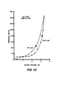
- Inflow-outflow concentration changes for creatinine were determined during in vitro tests at various flow modes, cycle times and volumes of fluid. Fluid volumes of 2.5 and 4.2 mls per package are shown in FIGURE.10(a) for the dialyzer apparatus, operated at trapezoid mode. Fractional removal is relatively independent of fill volume, as evidenced by similar values of K. The saw-tooth mode had a slightly lower fractional removal, because the average residence time of fluid in the dialyzer was shorter. For either mode, the slope for In(C/C i ) versus time varies with cycle time. As cycle time increases, the slope decreases. The mass transfer coefficient for the dialyzer is, therefore, dependent upon cycle time.
- An overall mass transfer coefficient can be determined for a cycle time yielding 50% efficiency (see above).
- the value of K O,0.5 is 13.3 x 10 -3 cm/min for the trapezoid flow at a fill volume of 4.2 mls per membrane package, and 14.6 x 10 -3 for 2.5 mls/pkg.
- the K O,0.5 for the saw-tooth flow is 8 x 10 -3 .
- a cycle time of 60 seconds would be necessary for 50% creatinine removal with trapezoid flow at 4.2 fill volume per package. Clearance for such a dialyzer would thus be 50% of the blood treatment rate, or approximately 2.1 ml/min/membrane package. Since each membrane package has a total area of about 200 cm , this represents a creatinine clearance of 105 ml/min M 2 .
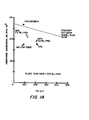
- FIGURE 10 (b) shows the mass transfer coefficient for dialyzer apparatus for models with no membrane spacer and with a pyramid type spacer as shown in FIGURES 1 through 3, operated at saw-tooth mode. Results for a given dialyzer are shown for several volumes connected by a solid line.
- the maximum value of V f/ A represents a "full" dialyzer, i.e., filled by syringe to about 300 mmHg.
- K O apparently increases with fill volume against theoretical prediction. This may be accounted for by a point-to-point variation in A, which could be a function of V f instead of constant as assumed in Equation 3.
- FIGURE 13(b) shows that dialyzers with no spacers are not as good as those with pyramidal spacers as shown in this invention, which resulted in much more uniform blood column thickness.
- the dialyzer apparatus of this invention (using a modified pyramidal spacer) had the optional mass transfer coefficient (10.3 x 10- 3 , at saw-tooth operation), the best obtained of any dialyzer apparatus.
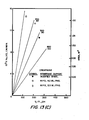
- FIGURE 10 contrasts different dialyzer apparatus designs, operating at trapezoid flow.
- Para- metric lines are included representing K O,0.5 , versus V v /A for 200 ml/min blood flow at various V f to achieve 50% creatinine removal.
- Scaled-up dialyzer membrane area is shown on the right-hand ordinate, calculated using flow rate (200 ml/min), cycle time (to give 50% efficiency), and blood column thickness.
- the "best" dialyzer can be found by comparing the parametric lines. Most desirable is a combination of small A and small V f . These criteria correspond to the higher- sloped lines, where the apparatus had a modified pyramidal spacer (MPS).
- MPS modified pyramidal spacer
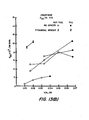
- FIGURE 11 depicts the theoretical predictions of clearance per M 2 surface area, for dialyzers of various blood film thickness, (2V f /A), at a blood treatment (or blood flow) rate of 200 ml/min. Included in FIGURE 11 are representative in vitro clearances for hollow fiber, coil, and plate dialyzers currently in use. Clearance per surface area for stretched nylon and MPS dialyzers are obtained from the data of in vitro fractional removal tests at trapezoid modes. The clearances of standard flow-through dialyzers are, in general, slightly less than the clearances predicted by the stagnant diffusion model.
- the clearances of stretched nylon and MPS dialyzers at a trapezoid mode are also slightly less than predicted.
- the clearances of reciprocating dialyzers at trapezoid modes are comparable to flow-through dialyzers of similar blood film thickness.
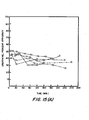
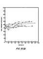
- FIGURE 12(a) indicates that these efficiencies were achieved (approximately) for creatinine removal, for all dialyzers tested. Efficiency of creatinine removal decreased slightly with time during the first hour, but it remained relatively constant afterwards, indicating a lack of significant saturation of sorbents near the membranes.
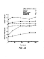
- FIGURE 13 shows the change in concentration of calcium, base excess, potassium, ammonium, and sodium, for the duration of one dialyzer test (7/2/80, 60 membrane packages).
- the sorbent suspension reciprocating dialyzer cannot function without some return of ammonium ions to the patient.
- inflow concentrations of ammonium to the dialyzer never goes above normal range.
- the animal's liver is able to metabolize the ammonia successfully during the dialysis procedure.
- the final outflow ammonium concentration is predictable from an equilibrium model, in which the ammonium flux into the dialyzer sorbent suspension is assumed to be equally mixed with all sorbent particles.
- this spacer has been shown to be able to handle denser slurry, over 500 ' g/L, have low resistance, high mass transfer, and provide a thin, uniform blood space.
- Caking was observed with 400 g/L of sorbents during a fractional test and a half hour pumping test with pressure/vacuum. No loss of "blood” movement was observed, however, during the pumping test.
- Mass transfer 8 x 10 -3 cm/min was along with producing a thin blood column with the apparatus having moderate resistance.
- the dialyzer apparatus may be operated for up to 240 minutes without significant loss in fill volume. During this time, two to three ml of sorbent suspension flows into and out of each membrane package suspension compartment. A small portion of overall resistance is related to sorbent suspension flow. In unidirectional flow, only about 50 ml of the same sorbent suspension will flow before marked increase in resistance occurs (time of flow proportional to V (1.26 - 1.53) ). The success of the sorbent suspension reciprocating dialyzer apparatus in maintaining the fluidity of the sorbents is felt to be due to:
- the resistance of the dialyzer is somewhat difficult to determine, due to the overlying importance of compliance in limiting flow. However, it does appear that the outflow resistance of the dialyzer is higher than inflow resistance. Long term operation of the dialyzer does not seem to alter its mechanical properties, and the dialyzer apparatus can be operated with a single blood access, at modest transmembrane pressures.
- the chemical efficiency of the reciprocating sorbent suspension dialyzer is markedly improved by the spacers of this invention on the dialysate side which produces a thin, flat blood column and yields a mass transfer coefficient of ten to 13 (depending on whether it was operated at "saw-tooth” or "trapezoid” flow pattern).
- This mass transfer coefficient is comparable to that of flow-through dialyzers with similar average blood column thckness.
- a creatinine clearance of 100 ml/min, with a blood flow rate of 200 ml/min, can be obtained with the apparatus of this invention with a dialyzer having about 1.4 M 2 surface area, operated at a 60 cycle with a 200 ml maximum fill volume.
- the sorbent suspension utilized in the animal tests yielded ion balance appropriate for patients in renal failure, and the calcium-sodium zeolite, in combination with urease, allowed urea nitrogen, Na, and K removal, and modest calcium return to the blood.
Landscapes
- Health & Medical Sciences (AREA)
- Urology & Nephrology (AREA)
- Chemical Kinetics & Catalysis (AREA)
- Heart & Thoracic Surgery (AREA)
- Chemical & Material Sciences (AREA)
- Engineering & Computer Science (AREA)
- Hematology (AREA)
- Biomedical Technology (AREA)
- Anesthesiology (AREA)
- Life Sciences & Earth Sciences (AREA)
- Animal Behavior & Ethology (AREA)
- General Health & Medical Sciences (AREA)
- Public Health (AREA)
- Veterinary Medicine (AREA)
- Water Supply & Treatment (AREA)
- Vascular Medicine (AREA)
- Emergency Medicine (AREA)
- External Artificial Organs (AREA)
- Separation Using Semi-Permeable Membranes (AREA)
Applications Claiming Priority (2)
| Application Number | Priority Date | Filing Date | Title |
|---|---|---|---|
| US204342 | 1980-11-05 | ||
| US06/204,342 US4348283A (en) | 1980-11-05 | 1980-11-05 | Reciprocating dialyzer having spacers |
Related Parent Applications (2)
| Application Number | Title | Priority Date | Filing Date |
|---|---|---|---|
| EP81305141A Division EP0051458B1 (de) | 1980-11-05 | 1981-10-29 | Alternierender Dialysator mit Trennplatten |
| EP81305141.4 Division | 1981-10-29 |
Publications (2)
| Publication Number | Publication Date |
|---|---|
| EP0152640A2 true EP0152640A2 (de) | 1985-08-28 |
| EP0152640A3 EP0152640A3 (de) | 1986-09-03 |
Family
ID=22757532
Family Applications (2)
| Application Number | Title | Priority Date | Filing Date |
|---|---|---|---|
| EP84201368A Withdrawn EP0152640A3 (de) | 1980-11-05 | 1981-10-29 | Membrandistanzplatte und alternierend bewegender Dialysator |
| EP81305141A Expired EP0051458B1 (de) | 1980-11-05 | 1981-10-29 | Alternierender Dialysator mit Trennplatten |
Family Applications After (1)
| Application Number | Title | Priority Date | Filing Date |
|---|---|---|---|
| EP81305141A Expired EP0051458B1 (de) | 1980-11-05 | 1981-10-29 | Alternierender Dialysator mit Trennplatten |
Country Status (8)
| Country | Link |
|---|---|
| US (1) | US4348283A (de) |
| EP (2) | EP0152640A3 (de) |
| JP (1) | JPS57107164A (de) |
| AT (1) | ATE22012T1 (de) |
| AU (1) | AU7708081A (de) |
| CA (1) | CA1173760A (de) |
| DE (1) | DE3175311D1 (de) |
| ES (1) | ES8304440A1 (de) |
Families Citing this family (31)
| Publication number | Priority date | Publication date | Assignee | Title |
|---|---|---|---|---|
| US4661246A (en) * | 1984-10-01 | 1987-04-28 | Ash Medical Systems, Inc. | Dialysis instrument with dialysate side pump for moving body fluids |
| JP2843634B2 (ja) * | 1989-03-06 | 1999-01-06 | 協和醗酵工業株式会社 | キサンチン誘導体 |
| US5277820A (en) * | 1992-02-06 | 1994-01-11 | Hemocleanse, Inc. | Device and method for extracorporeal blood treatment |
| US5919369A (en) * | 1992-02-06 | 1999-07-06 | Hemocleanse, Inc. | Hemofiltration and plasmafiltration devices and methods |
| US5670057A (en) * | 1995-04-28 | 1997-09-23 | Baxter International Inc. | Apparatus and method for automatically performing peritoneal equilibration tests |
| JP2001524839A (ja) * | 1996-03-08 | 2001-12-04 | ジョストラ ベントレイ インコーポレイテッド | 選択的膜/吸着手法による自己血液の回収 |
| US6235463B1 (en) | 1998-05-12 | 2001-05-22 | General Biotechnology, Llc | Sorbent method for removal of cryoprotectants from cryopreserved animal cells |
| US6113546A (en) | 1998-07-31 | 2000-09-05 | Scimed Life Systems, Inc. | Off-aperture electrical connection for ultrasonic transducer |
| US6406433B1 (en) | 1999-07-21 | 2002-06-18 | Scimed Life Systems, Inc. | Off-aperture electrical connect transducer and methods of making |
| US20090101577A1 (en) * | 2007-09-28 | 2009-04-23 | Fulkerson Barry N | Methods and Systems for Controlling Ultrafiltration Using Central Venous Pressure Measurements |
| US8597505B2 (en) | 2007-09-13 | 2013-12-03 | Fresenius Medical Care Holdings, Inc. | Portable dialysis machine |
| US9358331B2 (en) | 2007-09-13 | 2016-06-07 | Fresenius Medical Care Holdings, Inc. | Portable dialysis machine with improved reservoir heating system |
| US20090076434A1 (en) * | 2007-09-13 | 2009-03-19 | Mischelevich David J | Method and System for Achieving Volumetric Accuracy in Hemodialysis Systems |
| US9308307B2 (en) | 2007-09-13 | 2016-04-12 | Fresenius Medical Care Holdings, Inc. | Manifold diaphragms |
| US8240636B2 (en) | 2009-01-12 | 2012-08-14 | Fresenius Medical Care Holdings, Inc. | Valve system |
| US8105487B2 (en) | 2007-09-25 | 2012-01-31 | Fresenius Medical Care Holdings, Inc. | Manifolds for use in conducting dialysis |
| US8040493B2 (en) | 2007-10-11 | 2011-10-18 | Fresenius Medical Care Holdings, Inc. | Thermal flow meter |
| US8535522B2 (en) | 2009-02-12 | 2013-09-17 | Fresenius Medical Care Holdings, Inc. | System and method for detection of disconnection in an extracorporeal blood circuit |
| US8475399B2 (en) | 2009-02-26 | 2013-07-02 | Fresenius Medical Care Holdings, Inc. | Methods and systems for measuring and verifying additives for use in a dialysis machine |
| CA3057807C (en) | 2007-11-29 | 2021-04-20 | Thomas P. Robinson | System and method for conducting hemodialysis and hemofiltration |
| US20100184198A1 (en) * | 2009-01-16 | 2010-07-22 | Joseph Russell T | Systems and Methods of Urea Processing to Reduce Sorbent Load |
| CN105148344B (zh) | 2008-10-07 | 2019-06-11 | 弗雷塞尼斯医疗保健控股公司 | 用于透析系统的充灌系统和方法 |
| AU2009320007B2 (en) | 2008-10-30 | 2014-12-04 | Fresenius Medical Care Holdings, Inc. | Modular, portable dialysis system |
| US8182673B2 (en) * | 2009-01-29 | 2012-05-22 | Baxter International Inc. | Drain and fill logic for automated peritoneal dialysis |
| WO2010114932A1 (en) | 2009-03-31 | 2010-10-07 | Xcorporeal, Inc. | Modular reservoir assembly for a hemodialysis and hemofiltration system |
| US9201036B2 (en) | 2012-12-21 | 2015-12-01 | Fresenius Medical Care Holdings, Inc. | Method and system of monitoring electrolyte levels and composition using capacitance or induction |
| US9157786B2 (en) | 2012-12-24 | 2015-10-13 | Fresenius Medical Care Holdings, Inc. | Load suspension and weighing system for a dialysis machine reservoir |
| US20140263062A1 (en) | 2013-03-14 | 2014-09-18 | Fresenius Medical Care Holdings, Inc. | Universal portable machine for online hemodiafiltration using regenerated dialysate |
| US9433720B2 (en) | 2013-03-14 | 2016-09-06 | Fresenius Medical Care Holdings, Inc. | Universal portable artificial kidney for hemodialysis and peritoneal dialysis |
| US9354640B2 (en) | 2013-11-11 | 2016-05-31 | Fresenius Medical Care Holdings, Inc. | Smart actuator for valve |
| EP3046598A4 (de) | 2013-11-25 | 2017-06-14 | Bayer Healthcare, LLC | Präzise verabreichung von teildosierungen eines arzneimittels nach der verdünnung anhand eines injektors |
Family Cites Families (15)
| Publication number | Priority date | Publication date | Assignee | Title |
|---|---|---|---|---|
| US3412865A (en) * | 1964-11-16 | 1968-11-26 | John F. Lontz | Artificial kidney |
| US3540595A (en) * | 1965-05-18 | 1970-11-17 | Miles Lowell Edwards | Membrane fluid diffusion exchange device |
| US3413095A (en) * | 1965-06-14 | 1968-11-26 | Mogens L. Bramson | Membrane oxygenator |
| SE218441C1 (sv) * | 1965-07-21 | 1968-01-23 | Dialysanordning för rening av blod eller andra vätskor | |
| US3396849A (en) * | 1966-05-10 | 1968-08-13 | Univ Minnesota | Membrane oxygenator-dialyzer |
| US3362540A (en) * | 1966-08-24 | 1968-01-09 | Research Corp | Disc-shaped, multiple cone type dialyzer having a tapered flow path |
| US3907687A (en) * | 1968-12-07 | 1975-09-23 | Baxter Laboratories Inc | Plate dialyzer |
| US3564819A (en) * | 1970-02-24 | 1971-02-23 | Gen Electric | Membrane package construction |
| US4071444A (en) * | 1976-10-12 | 1978-01-31 | Purdue Research Foundation | Portable chemical reactor for use as an artificial kidney |
| JPS5828553B2 (ja) * | 1976-10-13 | 1983-06-16 | 三菱電機株式会社 | 気象エコ−の強度測定装置 |
| GB1591117A (en) * | 1976-10-14 | 1981-06-17 | Baxter Travenol Lab | Distribution system of blood treatment apparatus |
| SE442169B (sv) * | 1976-11-26 | 1985-12-09 | Sartorius Membranfilter Gmbh | Anordning for ultrafiltrering |
| US4132649A (en) * | 1977-03-28 | 1979-01-02 | Dresser Industries, Inc | Gasket arrangement for purification apparatus |
| JPS54141386A (en) * | 1978-04-26 | 1979-11-02 | Kuraray Co Ltd | Flat membrane type fluid treating apparatus |
| US4340475A (en) * | 1980-01-22 | 1982-07-20 | A.T. Ramot Plastics Ltd. | Membrane separation cell |
-
1980
- 1980-11-05 US US06/204,342 patent/US4348283A/en not_active Expired - Lifetime
-
1981
- 1981-10-29 AT AT81305141T patent/ATE22012T1/de not_active IP Right Cessation
- 1981-10-29 EP EP84201368A patent/EP0152640A3/de not_active Withdrawn
- 1981-10-29 DE DE8181305141T patent/DE3175311D1/de not_active Expired
- 1981-10-29 EP EP81305141A patent/EP0051458B1/de not_active Expired
- 1981-11-02 JP JP56176288A patent/JPS57107164A/ja active Pending
- 1981-11-04 ES ES506855A patent/ES8304440A1/es not_active Expired
- 1981-11-04 AU AU77080/81A patent/AU7708081A/en not_active Abandoned
- 1981-11-04 CA CA000389439A patent/CA1173760A/en not_active Expired
Also Published As
| Publication number | Publication date |
|---|---|
| EP0051458A2 (de) | 1982-05-12 |
| CA1173760A (en) | 1984-09-04 |
| EP0152640A3 (de) | 1986-09-03 |
| ES506855A0 (es) | 1983-03-01 |
| ES8304440A1 (es) | 1983-03-01 |
| ATE22012T1 (de) | 1986-09-15 |
| US4348283A (en) | 1982-09-07 |
| AU7708081A (en) | 1982-05-13 |
| JPS57107164A (en) | 1982-07-03 |
| EP0051458B1 (de) | 1986-09-10 |
| EP0051458A3 (en) | 1982-09-22 |
| DE3175311D1 (en) | 1986-10-16 |
Similar Documents
| Publication | Publication Date | Title |
|---|---|---|
| EP0051458B1 (de) | Alternierender Dialysator mit Trennplatten | |
| US3608729A (en) | Disposable dialyser pack with adsorbent | |
| US3884808A (en) | Wearable, self-regenerating dialysis appliance | |
| US4013564A (en) | Multipurpose metabolic assist system | |
| US4071444A (en) | Portable chemical reactor for use as an artificial kidney | |
| US6497675B1 (en) | Device for extracorporeal treatment of physiological fluids of organism | |
| US3483867A (en) | Artificial glomerulus and a method for treating blood | |
| JP6629197B2 (ja) | クロスフローろ過装置 | |
| US4518497A (en) | Blood treating system | |
| US5330420A (en) | Hemolysis detector | |
| US3522885A (en) | Parallel flow hemodialyzer | |
| CA1086235A (en) | Continuous removing system of blood substances by extra corporeal circulation | |
| US3212642A (en) | Artificial kidney | |
| SU553912A3 (ru) | Искусственна почка | |
| JP2013521862A (ja) | 透析システム脱気装置および関連するシステムおよび方法 | |
| EP0112173A2 (de) | Plasmaphorese | |
| EP0386048A1 (de) | Blutreinigungsvorrichtung. | |
| US10987460B2 (en) | Methods and systems of generating rapidly varying pressure amplitudes in fluidic circuits in a dialysis treatment system | |
| US3682817A (en) | Dialyzer | |
| US3464562A (en) | Dialyzing apparatus and method of making the same | |
| Catapano et al. | Blood flow outside regularly spaced hollow fibers: the future concept of membrane devices? | |
| US4565626A (en) | Apparatus for blood treatment by pressing blood into treating material and then drawing it out | |
| EP0112094A1 (de) | Vorrichtung zur Blutbehandlung | |
| JPH1057476A (ja) | 膜分離装置 | |
| Barile et al. | A reciprocating, single‐needle hemodialyzer with bidirectional flow of sorbent suspension |
Legal Events
| Date | Code | Title | Description |
|---|---|---|---|
| PUAI | Public reference made under article 153(3) epc to a published international application that has entered the european phase |
Free format text: ORIGINAL CODE: 0009012 |
|
| 17P | Request for examination filed |
Effective date: 19841013 |
|
| AC | Divisional application: reference to earlier application |
Ref document number: 51458 Country of ref document: EP |
|
| AK | Designated contracting states |
Designated state(s): AT BE CH DE FR GB IT LI LU NL SE |
|
| PUAL | Search report despatched |
Free format text: ORIGINAL CODE: 0009013 |
|
| AK | Designated contracting states |
Kind code of ref document: A3 Designated state(s): AT BE CH DE FR GB IT LI LU NL SE |
|
| STAA | Information on the status of an ep patent application or granted ep patent |
Free format text: STATUS: THE APPLICATION IS DEEMED TO BE WITHDRAWN |
|
| 18D | Application deemed to be withdrawn |
Effective date: 19870430 |
|
| RIN1 | Information on inventor provided before grant (corrected) |
Inventor name: ASH, STEPHEN RICHARD |