EP0152283A2 - Improvements in or relating to beverage dispensing apparatus - Google Patents
Improvements in or relating to beverage dispensing apparatus Download PDFInfo
- Publication number
- EP0152283A2 EP0152283A2 EP85300834A EP85300834A EP0152283A2 EP 0152283 A2 EP0152283 A2 EP 0152283A2 EP 85300834 A EP85300834 A EP 85300834A EP 85300834 A EP85300834 A EP 85300834A EP 0152283 A2 EP0152283 A2 EP 0152283A2
- Authority
- EP
- European Patent Office
- Prior art keywords
- beverage
- reservoir
- concentrate
- piston
- dispensing
- Prior art date
- Legal status (The legal status is an assumption and is not a legal conclusion. Google has not performed a legal analysis and makes no representation as to the accuracy of the status listed.)
- Ceased
Links
Images


Classifications
-
- B—PERFORMING OPERATIONS; TRANSPORTING
- B67—OPENING, CLOSING OR CLEANING BOTTLES, JARS OR SIMILAR CONTAINERS; LIQUID HANDLING
- B67D—DISPENSING, DELIVERING OR TRANSFERRING LIQUIDS, NOT OTHERWISE PROVIDED FOR
- B67D1/00—Apparatus or devices for dispensing beverages on draught
- B67D1/08—Details
- B67D1/12—Flow or pressure control devices or systems, e.g. valves, gas pressure control, level control in storage containers
- B67D1/1284—Ratio control
- B67D1/1286—Ratio control by mechanical construction
- B67D1/1288—Multi-chamber piston pumps
-
- B—PERFORMING OPERATIONS; TRANSPORTING
- B67—OPENING, CLOSING OR CLEANING BOTTLES, JARS OR SIMILAR CONTAINERS; LIQUID HANDLING
- B67D—DISPENSING, DELIVERING OR TRANSFERRING LIQUIDS, NOT OTHERWISE PROVIDED FOR
- B67D1/00—Apparatus or devices for dispensing beverages on draught
- B67D1/0015—Apparatus or devices for dispensing beverages on draught the beverage being prepared by mixing at least two liquid components
- B67D1/0016—Apparatus or devices for dispensing beverages on draught the beverage being prepared by mixing at least two liquid components the beverage being stored in an intermediate container before dispensing, i.e. pre-mix dispensers
-
- B—PERFORMING OPERATIONS; TRANSPORTING
- B67—OPENING, CLOSING OR CLEANING BOTTLES, JARS OR SIMILAR CONTAINERS; LIQUID HANDLING
- B67D—DISPENSING, DELIVERING OR TRANSFERRING LIQUIDS, NOT OTHERWISE PROVIDED FOR
- B67D1/00—Apparatus or devices for dispensing beverages on draught
- B67D1/0042—Details of specific parts of the dispensers
- B67D1/0043—Mixing devices for liquids
- B67D1/0054—Recirculation means
-
- B—PERFORMING OPERATIONS; TRANSPORTING
- B67—OPENING, CLOSING OR CLEANING BOTTLES, JARS OR SIMILAR CONTAINERS; LIQUID HANDLING
- B67D—DISPENSING, DELIVERING OR TRANSFERRING LIQUIDS, NOT OTHERWISE PROVIDED FOR
- B67D1/00—Apparatus or devices for dispensing beverages on draught
- B67D1/07—Cleaning beverage-dispensing apparatus
-
- B—PERFORMING OPERATIONS; TRANSPORTING
- B67—OPENING, CLOSING OR CLEANING BOTTLES, JARS OR SIMILAR CONTAINERS; LIQUID HANDLING
- B67D—DISPENSING, DELIVERING OR TRANSFERRING LIQUIDS, NOT OTHERWISE PROVIDED FOR
- B67D2210/00—Indexing scheme relating to aspects and details of apparatus or devices for dispensing beverages on draught or for controlling flow of liquids under gravity from storage containers for dispensing purposes
- B67D2210/00028—Constructional details
- B67D2210/00031—Housing
-
- B—PERFORMING OPERATIONS; TRANSPORTING
- B67—OPENING, CLOSING OR CLEANING BOTTLES, JARS OR SIMILAR CONTAINERS; LIQUID HANDLING
- B67D—DISPENSING, DELIVERING OR TRANSFERRING LIQUIDS, NOT OTHERWISE PROVIDED FOR
- B67D2210/00—Indexing scheme relating to aspects and details of apparatus or devices for dispensing beverages on draught or for controlling flow of liquids under gravity from storage containers for dispensing purposes
- B67D2210/00028—Constructional details
- B67D2210/00099—Temperature control
- B67D2210/00104—Cooling only
Definitions
- This invention relates to beverage dispensing apparatus and more particularly, but not exclusively, to apparatus for dispensing a beverage such as a fruit juice.
- Beverage such as fruit juice formed from, for example, a mixture of a fruit juice syrup or concentrate and water are subject to the growth of bacteria particularly, if left in a stagnant condition for any period of time. Furthermore, it is desirable in beverage dispensing apparatus for dispensing such a beverage to ensure that the apparatus can be readily cleaned in order to again inhibit the growth of bacteria.
- the growth of bacteria in a beverage can be inhibited by, for example, increasing the hydrogen ion concentration, p.H• value, of the beverage by the addition of a preservative such as benzoic acid.
- a preservative such as benzoic acid.
- the beverage which is thus dispensed is not what could be termed a "pure" fruit juice due to the addition of such a preservative.
- the object of this invention is to provide apparatus for dispensing a beverage formed of, for example, a "pure” fruit juice or the like, in which the growth of bacteria is inhibited or can be kept to a minimum.
- the return pipe constitutes a restriction or is provided with a restriction to maintain pressure in the fluid circuit and provide adequate flow through the outlet.
- the restriction provided in the return pipe is adjustable to adjust the pressure in the fluid circuit.
- the apparatus preferably, includes a reservoir for containing the beverage.
- the flow pipe is connected to a lower portion of the reservoir.
- the beverage is formed from a concentrate which is diluted with a dilutant, such as water
- a concentrate container is mounted in the beverage reservoir.
- a metering pump is, preferably, connected to the concentrate container for drawing concentrate therefrom and supplying the concentrate and the dilutant in a predetermined ratio to the beverage reservoir.
- apparatus for dispensing a beverage comprises fluid supply means, an outlet through which the beverage is dispensed, and a reservoir for containing the beverage, wherein the reservoir is connected to the apparatus by quick release coupling means to facilitate removal thereof.
- the reservoir is slidably mounted on or forms part of a slidable tray or door of a housing for the apparatus to enable the reservoir to be wholly or partially removed from the apparatus.
- the quick release coupling means is adapted to be self sealing to enable the reservoir to be removed whilst wholly or partially full of beverage.
- the fluid supply means preferably, includes a fluid circuit which comprises a flow pipe and a return pipe, and pump means for continuously circulating the beverage around the fluid circuit.
- the quick release coupling means is adapted to releasably connect the reservoir to the flow pipe and return pipe of the fluid circuit and, where the beverage is formed from a concentrate which is diluted with water and the reservoir contains a concentrate container and metering pump, the quick release coupling means is also adapted to releasably connect the reservoir to a water supply pipe.
- a cleaning tank of similar construction to the reservoir is, preferably, provided so as to be capable of insertion into the apparatus after removal of the reservoir therefrom.
- the cleaning tank is provided with two compartments, one compartment, which is to contain a cleaning fluid, being adapted to be connected by the quick release coupling means to the flow pipe and the other compartment, which is to receive the cleaning fluid after circulation through the apparatus, being adapted to be connected by the quick release coupling means to the return pipe.
- the two compartments in the cleaning tank are formed by a partition wall in the cleaning tank.
- the partition wall preferably, extends upwardly from the base of the cleaning tank for a distance which is less than the full height of the cleaning tank so that when, prior to commencement of the cleaning operation, both compartments are substantially filled with cleaning fluid, communication between the two compartments is provided during the cleaning operation by the flow of cleaning fluid over the partition wall from said other compartment to said one compartment.
- the reservoir may be a flexible collapsible reservoir which is connected to a junction of the flow pipe and the return pipe by quick release coupling means.
- connection between the reservoir and the junction of the flow pipe and the return pipe is provided with non-return valve means adapted to permit flow of beverage from the reservoir into the fluid circuit but to prevent reverse flow of fluid from the fluid circuit into the reservoir.
- bleed valve means is provided in the return pipe portion of the fluid circuit to allow filling thereof.
- the piston in said one chamber is movable by the dilutant against the action of resilient means so that when the supply of dilutant is disconnected, the piston is moved by the resilient means to displace dilutant from said one chamber and produce corresponding movement of the piston in the other chamber to displace concentrate therefrom.
- valve means is provided for controlling the supply of dilutant to said one chamber of the metering pump.
- a vending machine having a coin or token operated mechanism for initiating the vending of a beverage comprises apparatus for dispensing a beverage according to said one aspect or said other aspect or said further aspect of this invention.
- a method of dispensing a beverage comprises continuously circulating the beverage under pressure around a fluid circuit, cooling the beverage, and dispensing the beverage directly from the fluid circuit.
- the beverage is stored in a reservoir and the beverage is continuously circulated from the reservoir around the fluid circuit.
- the beverage is mixed from a concentrate and a dilutant in predetermined ratios and supplied to the reservoir by a metering pump operated by the dilutant.
- the reservoir 10 is provided with an external lining 12 formed of an insulating material such as polystyrene or the like.
- a further portion of the flow pipe 14 extends from the cooling coil 18 to one or more dispensing valves or taps 32.
- the dispensing valves or taps 32 draw the beverage directly from the flow pipe 14 and dispense the beverage when the valve or tap 32 is opened.
- the valve or tap 32 is closed, the beverage supplied thereto through the flow pipe 14 is returned, in the case of the valve or tap 32 shown, to a return pipe 34, which extends parallel to the flow pipe 14 and is connected to the reservoir 10 at a point below the level of the beverage therein.
- dispensing valve or tap 32 thus constitutes part of the beverage supply circuit and beverage is not retained in a stagnant condition in said valve or tap.
- a concentrate container 40 is mounted in the reservoir 10 and is connected to a metering pump indicated generally at 42.
- the pump 42 is also provided with a second chamber 52 having a piston 54 which is a close sliding fit mounted therein.
- the piston 54 is drivably connected to the piston 46 by a connecting rod 56 and the lower portion of the second chamber 52 is connected via a non-return valve 58 to the concentrate container 40.
- the solenoid operated valve 50 is then moved to a second position disconnecting the chamber 44 from the water supply and allowing water therein to flow via the valve 50 to an outlet 60 leading to the reservoir 10 as the piston 46 moves under the action of the spring 48 to the position shown in Figure 4 of the drawings.
- connection of the piston 46 to the piston 54 by the connecting rod 56 produces corresponding movement of the piston 54 to discharge the concentrate in the chamber 52 via a non-return valve 62 in the direction of arrow B through the outlet 60 into the reservoir 10.
- the flow pipe 114 extends from the cooling coil in the heat exchanger 118 to one or more dispensing valves or taps 132.
- the dispensing valves or taps 132 draw the beverage directly from the flow pipe 114 and dispense the beverage when the valve or tap 132 is opened.
- the valve or tap 132 is closed, the beverage supplied thereto through the flow pipe 114 is returned, in the case of the valve or tap 132 shown, to a return pipe 134 which extends parallel to the flow pipe 114 and is connected to the reservoir 110.
- the flow pipe 114 and the return pipe 134 are enclosed within a layer of insulating material 136 to ensure that the beverage during its passage through the flow pipe 114 and the return pipe 134 is kept at the lowest possible temperature which in order to inhibit bacteriological growth should be below 40 degrees Fahrenheit.
- the pump 116 continuously circulates the beverage from the reservoir 110 through the flow pipe 114 via the heat exchanger 118 and returns the beverage to the reservoir 110 via the return pipe 134 so that the beverage is not left in a stagnant condition and this again inhibits bacteriological growth.
- a concentrate container 140 is mounted in the reservoir 110 and is connected to a metering pump indicated generally at 142.
- the pump 142 comprises a first chamber 144 having a piston 146 slidably mounted therein and movable against the action of a spring 148.
- the lower portion of the first chamber 144 of the pump 142 is connected via a solenoid-operated valve 150 to a mains water supply 166 so that in one position of the valve 150 water is supplied under pressure through the valve 150 to the chamber 144 to move the piston 146 against the action of the spring 148 to the position shown in Figure 7 of the drawings.
- the ratio of the mixture of concentrate to water is determined by the ratio of the cross-sectional areas of the chambers 152 and 144 and thus the pump 142 supplies a mixture having a consistent ratio of concentrate to water irrespective of the length of travel of the pistons 146 and 154.
- this ratio of the mixture is to be changed it would be possible to replace the pump 142 with an alternative pump having different ratios of cross-sectional areas of the chambers therein.
- the reservoir 110 is also provided with a liquid level sensing mechanism (not shown) which, when the level of beverage therein falls below a predetermined value, actuates the solenoid 150 via a timing mechanism (not shown).
- the timing mechanism produces cyclic movements of the solenoid valve 150 thus producing corresponding pumping strokes of the pistons 146 and 154 of the metering pump 142.
- the liquid level sensing means de-activates the solenoid-operated valve 150.
- the dispensing apparatus is mounted within a housing 170 which is provided with a fold down flap 172.
- the reservoir 110 is provided with self-sealing quick release couplings 174 to enable the reservoir 110 to be disconnected from the flow pipe 114, the return pipe 134 and the mains water supply 166.
- roller bearings 176 can be replaced by other types of friction reducing slides or alternatively, the reservoir 110 can be formed as an integral part of a sliding tray or sliding drawer formed in the housing.
- the quick release coupling connectors 174 each consist of male and female portions 178 and 180 respectively and it is preferable for the female portion 180 to be mounted on the reservoir 110.
- the male portion 178 of the connector 174 includes a spring loaded valve member 182 which is urged by the spring on to a seat to effect sealing thereof when the connector is in the disconnected condition.
- a rod 184 extends from the valve member 182 and is adapted to engage a spring loaded ball in the female portion 180 of the connector 174 when the male and female portions 178 and 180 are in their connected condition.
- the rod 184 not only lifts the spring loaded ball 186 of the female portion 180 off its seat but also lifts the valve member 182 of the male portion 178 off its associated seat so that liquid can flow through the coupling connector 174 in this connected condition.
- the self sealing nature of the connectors 174 enables the reservoir 110 to be removed from the housing 170 even when the reservoir is wholly or partially full so that cleaning of the dispensing apparatus can be carried out at any desired period of time without wastage of beverage which is already in the reservoir 110.
- the open top of the reservoir 110 is provided with a close fitting lid (not shown) to inhibit the ingress of any extraneous matter.
- a separate cleaning container (not shown) of similar construction to the reservoir 110 is inserted after the reservoir 110 has been removed.
- the cleaning container is divided by a partition extending upwardly from the base into two separate compartments which are respectively connected to the flow pipe 114 and the return pipe 134 by the connectors 174.
- the compartment which is connected to the flow pipe 114 has a cleaning fluid provided therein and after insertion of the cleaning container into the housing 170, the apparatus is operated so that the cleaning fluid is pumped through the flow pipe and then returned through the return pipe 134 into the other compartment of the cleaning container.
- both compartments of the cleaning container are filled with cleaning fluid and the partition is arranged so that it does not extend to the full height of the cleaning container so that as fluid is withdrawn through the flow pipe 114 from one compartment and is returned to the other compartment of the container through the return pipe 134, the liquid can flow over the top of the partition so that continuous circulation of the cleaning fluid can be maintained.
- the fluid circuit and the remainder of the apparatus is substantially identical to the beverage dispensing apparatus previously described with reference to Figures 5 to 9 of the drawings but a bleed valve 208 is mounted in the return pipe portion of the fluid circuit to enable the fluid circuit . to be completely filled with the beverage which is to be dispensed.
- the container 200 is of the disposable type, which once the beverage therein has been used, is then removed and replaced with a new full container.
- the bleed valve 208 consists of a spring loaded valve member 210 which in the normal position shown in Figure 11 of the drawings allows fluid to flow therethrough through the return pipe.
- valve member 210 When the valve member 210 is manually moved against the action of the spring to the position shown in Figure 12 of the drawings, fluid is withdrawn from the flow pipe to bleed or vent the fluid circuit.
- non-return valve 204 allows fluid to flow from the container 200 into the fluid circuit but prevents the return flow of fluid from the fluid circuit when the apparatus is in operation and the bleed valve 208 enables the fluid circuit to be fully filled with liquid when a container 200 is first mounted thereon.
- a self-sealing quick release connector is provided between the container 200 and the pipe 202 to enable the container 200 to be removed even if the container 200 is still partially full of beverage.
- additional cooling of the product in the reservoir 110 or container 200 is provided by effecting cooling of the reservoir 110 or container 200 itself by utilising the heat exchanger 118 or locating part of the fluid circuit in the housing 170 adjacent to the reservoir 110 or container 200.
- the fluid circuit and the components associated therewith are arranged, when the reservoir 110 or container 200 are empty, the pump 116 switched off and the or each tap 132 is or are opened, to be self-draining to facilitate cleaning of the fluid circuit.
- Additional, fluid circuits, product reservoirs, pumps and cooling coils may be provided to enable additional products to be dispensed.
- a vending machine having a coin or token operated mechanism for initiating the vending of a beverage can be constructed to include beverage dispensing apparatus according to the first second or third embodiment of this invention, the coin or token operated mechanism being arranged to operate the dispensing valve or tap 32 or 132 of the apparatus after a conventional cup dropping mechanism has placed a cup therebeneath.
Landscapes
- Engineering & Computer Science (AREA)
- Mechanical Engineering (AREA)
- Devices For Dispensing Beverages (AREA)
Abstract
@ Apparatus for dispensing a beverage consisting of a fluid circuit having a flow pipe and a return pipe, cooling means for cooling the beverage, pump means for continuously circulating the beverage around the fluid-circuit, one or more dispensing valves or taps in the fluid circuit through which the beverage is dispensed, and a reservoir for containing the beverage, said reservoir being connected to the apparatus by quick release coupling means to facilitate removal thereof. Where the beverage is to be formed of two or more liquids, a metering pump is provided to effect mixing of the beverage and the supply thereof to the reservoir. The reservoir may also be of the disposable collapsible type which is again provided with quick release coupling means to enable it to be removed from the apparatus.
Description
- This invention relates to beverage dispensing apparatus and more particularly, but not exclusively, to apparatus for dispensing a beverage such as a fruit juice.
- Beverage such as fruit juice formed from, for example, a mixture of a fruit juice syrup or concentrate and water are subject to the growth of bacteria particularly, if left in a stagnant condition for any period of time. Furthermore, it is desirable in beverage dispensing apparatus for dispensing such a beverage to ensure that the apparatus can be readily cleaned in order to again inhibit the growth of bacteria.
- The growth of bacteria in a beverage can be inhibited by, for example, increasing the hydrogen ion concentration, p.H• value, of the beverage by the addition of a preservative such as benzoic acid. However, the beverage which is thus dispensed is not what could be termed a "pure" fruit juice due to the addition of such a preservative.
- It is also known that the growth of bacteria in a beverage of this type can be kept to a minimum by maintaining the beverage at a temperature below 40 degrees Fahrenheit.
- The object of this invention is to provide apparatus for dispensing a beverage formed of, for example, a "pure" fruit juice or the like, in which the growth of bacteria is inhibited or can be kept to a minimum.
- According to one aspect bf this invention, apparatus for dispensing a beverage includes a fluid circuit which comprises a flow pipe and a return pipe, pump means for continuously circulating the beverage around the fluid circuit, cooling means for cooling the beverage, and an outlet in the fluid circuit through which the beverage is dispensed.
- Preferably, the return pipe constitutes a restriction or is provided with a restriction to maintain pressure in the fluid circuit and provide adequate flow through the outlet.
- Preferably, also, the restriction provided in the return pipe is adjustable to adjust the pressure in the fluid circuit.
- The apparatus, preferably, includes a reservoir for containing the beverage.
- Preferably, the flow pipe is connected to a lower portion of the reservoir.
- Preferably, also, where the beverage is formed from a concentrate which is diluted with a dilutant, such as water, a concentrate container is mounted in the beverage reservoir.
- A metering pump is, preferably, connected to the concentrate container for drawing concentrate therefrom and supplying the concentrate and the dilutant in a predetermined ratio to the beverage reservoir.
- According to another aspect of this invention, apparatus for dispensing a beverage comprises fluid supply means, an outlet through which the beverage is dispensed, and a reservoir for containing the beverage, wherein the reservoir is connected to the apparatus by quick release coupling means to facilitate removal thereof.
- Preferably, the reservoir is slidably mounted on or forms part of a slidable tray or door of a housing for the apparatus to enable the reservoir to be wholly or partially removed from the apparatus.
- Preferably, also, the quick release coupling means is adapted to be self sealing to enable the reservoir to be removed whilst wholly or partially full of beverage.
- The fluid supply means, preferably, includes a fluid circuit which comprises a flow pipe and a return pipe, and pump means for continuously circulating the beverage around the fluid circuit. Preferably, the quick release coupling means is adapted to releasably connect the reservoir to the flow pipe and return pipe of the fluid circuit and, where the beverage is formed from a concentrate which is diluted with water and the reservoir contains a concentrate container and metering pump, the quick release coupling means is also adapted to releasably connect the reservoir to a water supply pipe.
- A cleaning tank of similar construction to the reservoir is, preferably, provided so as to be capable of insertion into the apparatus after removal of the reservoir therefrom.
- Preferably, the cleaning tank is provided with two compartments, one compartment, which is to contain a cleaning fluid, being adapted to be connected by the quick release coupling means to the flow pipe and the other compartment, which is to receive the cleaning fluid after circulation through the apparatus, being adapted to be connected by the quick release coupling means to the return pipe.
- Preferably, also, the two compartments in the cleaning tank are formed by a partition wall in the cleaning tank.
- Where it is desired to continuously circulate cleaning fluid through the fluid circuit, the partition wall, preferably, extends upwardly from the base of the cleaning tank for a distance which is less than the full height of the cleaning tank so that when, prior to commencement of the cleaning operation, both compartments are substantially filled with cleaning fluid, communication between the two compartments is provided during the cleaning operation by the flow of cleaning fluid over the partition wall from said other compartment to said one compartment.
- According to a further aspect of this invention, the reservoir may be a flexible collapsible reservoir which is connected to a junction of the flow pipe and the return pipe by quick release coupling means.
- Preferably, the connection between the reservoir and the junction of the flow pipe and the return pipe is provided with non-return valve means adapted to permit flow of beverage from the reservoir into the fluid circuit but to prevent reverse flow of fluid from the fluid circuit into the reservoir.
- Preferably, also, bleed valve means is provided in the return pipe portion of the fluid circuit to allow filling thereof.
- According to yet another aspect of this invention, a metering pump for use in apparatus for dispensing a beverage formed of a concentrate and a dilutant comprises two chambers each having a piston mounted therein, the pistons in the two chambers being drivably connected together so that movement of the piston in one chamber under the action of the dilutant produces movement of the piston in the other chamber to draw concentrate from a concentrate container into said other chamber.
- Preferably, the piston in said one chamber is movable by the dilutant against the action of resilient means so that when the supply of dilutant is disconnected, the piston is moved by the resilient means to displace dilutant from said one chamber and produce corresponding movement of the piston in the other chamber to displace concentrate therefrom.
- Preferably, also, valve means is provided for controlling the supply of dilutant to said one chamber of the metering pump.
- According to yet a further aspect of this invention, a vending machine having a coin or token operated mechanism for initiating the vending of a beverage comprises apparatus for dispensing a beverage according to said one aspect or said other aspect or said further aspect of this invention.
- According to another further aspect of this invention, a method of dispensing a beverage comprises continuously circulating the beverage under pressure around a fluid circuit, cooling the beverage, and dispensing the beverage directly from the fluid circuit.
- Preferably, the beverage is stored in a reservoir and the beverage is continuously circulated from the reservoir around the fluid circuit.
- Preferably, also, the beverage is mixed from a concentrate and a dilutant in predetermined ratios and supplied to the reservoir by a metering pump operated by the dilutant.
- Preferred embodiments of this invention will now be described, by way of example only, with reference to the accompanying drawings of which:-
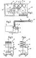
- Figure 1 is a diagrammatic plan view of a beverage dispensing apparatus according to a first embodiment,
- Figure 2 is a diagrammatic side elevation of a fluid circuit portion of the apparatus,
- Figure 3 is a diagrammatic side elevation of a metering pump of the apparatus in a first position,
- Figure 4 is a diagrammatic side elevation of the metering pump of the apparatus in a second position,
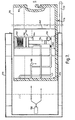
- Figure 5 is a front elevation of a beverage dispensing apparatus according to a second embodiment,
- Figure 6 is a plan view of the beverage dispensing apparatus shown in Figure 5,
- Figure 7 is a partially sectioned side elevation of the beverage dispensing apparatus shown in Figure 6,
- Figure 8 is a diagrammatic sectional side elevation of a quick release coupling for use in the beverage dispensing apparatus in its connected condition,
- Figure 9 is a diagrammatic sectional side elevation of the quick release coupling shown in Figure 8 in its disconnected condition,
- Figure 10 is a circuit diagram of a beverage dispensing apparatus according to a third embodiment,
- Figure 11 is a diagrammatic sectional side elevation of a bleed valve for use in the apparatus shown in Figure 10 with the bleed valve in its inoperative position, and
- Figure 12 is a diagrammatic sectional side elevation of the bleed valve shown in Figure 11 in its operative position.
- Referring now to Figures 1 to 4 of the drawings, in a first embodiment, dispensing apparatus for dispensing a beverage formed of a mixture of fruit juice concentrate and water comprises a
reservoir 10 for containing the mixed beverage. Thereservoir 10 is provided with anexternal lining 12 formed of an insulating material such as polystyrene or the like. - A
flow pipe 14 connects the lower portion of thereservoir 10 to an electrically drivenpump 16. Thepump 16 is connected to acooling coil 18 mounted in acooling bath 20 by a further portion of theflow pipe 14. - A conventional refrigeration system indicated generally at 22 including a compressor 24, fan 26, condenser 28, and a
refrigeration coil 30 is provided to effect cooling of the water in thebath 20. - A further portion of the
flow pipe 14 extends from thecooling coil 18 to one or more dispensing valves or taps 32. The dispensing valves ortaps 32, of which only one is shown in the drawings, draw the beverage directly from theflow pipe 14 and dispense the beverage when the valve ortap 32 is opened. When the valve ortap 32 is closed, the beverage supplied thereto through theflow pipe 14 is returned, in the case of the valve ortap 32 shown, to areturn pipe 34, which extends parallel to theflow pipe 14 and is connected to thereservoir 10 at a point below the level of the beverage therein. - It will be appreciated that the dispensing valve or
tap 32 thus constitutes part of the beverage supply circuit and beverage is not retained in a stagnant condition in said valve or tap. - The
flow pipe 14 and thereturn pipe 34 are enclosed within a layer of insulating material 36 to ensure that the beverage during its passage through theflow pipe 14 and thereturn pipe 34 is kept at the lowest possible temperature, which in order to inhibit bacteriological growth should be below 40 degrees Fahrenheit. - In addition, the
pump 16 continuously circulates the beverage from thereservoir 10 through theflow pipe 14 via the cooling coil and returns the beverage to thereservoir 10 via thereturn pipe 34 so that the beverage is not left in a stagnant condition and this again inhibits bacteriological growth. - A
restriction 38 having an adjustable aperture is formed in thereturn pipe 34 adjacent to or at its point of connection to thereservoir 10 so that the pressure of beverage in theflow pipe 14 created by thepump 16 can be adjusted to provide adequate flow through the or each dispensingtap 32. - A
concentrate container 40 is mounted in thereservoir 10 and is connected to a metering pump indicated generally at 42. - A
pump 42 comprises afirst chamber 44 having apiston 46 slidably mounted therein and movable against the action of aspring 48. The lower portion of thefirst chamber 44 of thepump 42 is connected via a solenoid operatedvalve 50 to acooling coil 64 mounted in thecooling bath 20. Thecooling coil 64 is connected to a regulatedmains water supply 66 so that in one position of thevalve 50, pre-chilled water is supplied under pressure through thecooling coil 64 and thevalve 50 to thechamber 44 to move thepiston 46 against-the action of thespring 48 to the position shown in Figure 3 of the drawings. - • The
pump 42 is also provided with asecond chamber 52 having apiston 54 which is a close sliding fit mounted therein. Thepiston 54 is drivably connected to thepiston 46 by a connectingrod 56 and the lower portion of thesecond chamber 52 is connected via anon-return valve 58 to theconcentrate container 40. - When the
piston 46 is moved against the action of thespring 48 to the position shown in Figure 3 of the drawings, concentrate is drawn from thecontainer 40 into thesecond chamber 52 via thenon-return valve 58 in the direction of arrow A. - The solenoid operated
valve 50 is then moved to a second position disconnecting thechamber 44 from the water supply and allowing water therein to flow via thevalve 50 to anoutlet 60 leading to thereservoir 10 as thepiston 46 moves under the action of thespring 48 to the position shown in Figure 4 of the drawings. - The connection of the
piston 46 to thepiston 54 by the connectingrod 56 produces corresponding movement of thepiston 54 to discharge the concentrate in thechamber 52 via anon-return valve 62 in the direction of arrow B through theoutlet 60 into thereservoir 10. - It will be appreciated that the ratio of the mixture of concentrate to water is determined by the ratio of the cross-sectional areas of the
chambers pump 42 supplies a mixture having a consistent ratio of concentrate to water irrespective of the length of travel of thepistons - The
reservoir 10 is also provided with. a liquid level sensing mechanism (not shown) which, when the level of beverage therein falls below a predetermined value, actuates thesolenoid valve 50 via a timing mechanism (not shown). The timing mechanism produces cyclic movements of thesolenoid valve 50 between its first and 4L second position thus producing corresponding pumping strokes of thepistons reservoir 10 reaches a predetermined maximum value, the liquid level sensing means (not shown) de-activates the solenoid operatedvalve 50. - It will be appreciated that utilising water pressure as the source of power for the metering pump simplifies the construction thereof and makes the pump capable of being easily disconnected from the dispensing apparatus when it requires cleaning.
- Referring now to Figures 5 to 9 of the drawings, in a second embodiment a dispensing apparatus for dispensing a beverage formed of a mixture of fruit juice concentrate and water comprises a
reservoir 110 for containing the mixed beverage. Thereservoir 110 is provided with anexternal lining 112 formed of an insulating material such as polystyrene or the like. - A
flow pipe 114 connects thereservoir 110 to an electrically drivenpump 116. Thepump 116 is connected by a further portion of theflow pipe 114 to aheat exchanger 118 formed by a cooling coil (not shown) which is mounted in a cooling bath (not shown). A conventional refrigeration system indicated generally at 122 which includes a compressor (not shown), a fan (not shown), acondenser 128, and a refrigeration coil (not shown) is provided to effect cooling of water in the cooling bath of theheat exchanger 118. - The
flow pipe 114 extends from the cooling coil in theheat exchanger 118 to one or more dispensing valves or taps 132. The dispensing valves or taps 132, of which only one is shown in the drawings, draw the beverage directly from theflow pipe 114 and dispense the beverage when the valve or tap 132 is opened. When the valve or tap 132 is closed, the beverage supplied thereto through theflow pipe 114 is returned, in the case of the valve or tap 132 shown, to areturn pipe 134 which extends parallel to theflow pipe 114 and is connected to thereservoir 110. - It will be realised that other forms of refrigeration systems could be utilised on the above described system modified to, for example, locate the
heat exchanger 118 in thereturn pipe 134 without departing from the scope of this invention. - It will be appreciated that the dispensing valve or tap 132 thus constitutes part of the beverage supply circuit and beverage is not retained in a stagnant condition in said valve or tap.
- The
flow pipe 114 and thereturn pipe 134 are enclosed within a layer of insulatingmaterial 136 to ensure that the beverage during its passage through theflow pipe 114 and thereturn pipe 134 is kept at the lowest possible temperature which in order to inhibit bacteriological growth should be below 40 degrees Fahrenheit. - In addition, the
pump 116 continuously circulates the beverage from thereservoir 110 through theflow pipe 114 via theheat exchanger 118 and returns the beverage to thereservoir 110 via thereturn pipe 134 so that the beverage is not left in a stagnant condition and this again inhibits bacteriological growth. - A restriction (not shown) having an adjustable aperture is formed in the
return pipe 134 adjacent to or at its point of connection to thereservoir 110, or alternatively, the size of thereturn pipe 134 is selected so that the pressure of the beverage in theflow pipe 114 created by thepump 116 can either be adjusted or is arranged to be sufficient to provide adequate flow through the or each dispensingtap 132. - A
concentrate container 140 is mounted in thereservoir 110 and is connected to a metering pump indicated generally at 142. Thepump 142 comprises afirst chamber 144 having a piston 146 slidably mounted therein and movable against the action of aspring 148. The lower portion of thefirst chamber 144 of thepump 142 is connected via a solenoid-operatedvalve 150 to amains water supply 166 so that in one position of thevalve 150 water is supplied under pressure through thevalve 150 to thechamber 144 to move the piston 146 against the action of thespring 148 to the position shown in Figure 7 of the drawings. - The
pump 142 is also provided with asecond chamber 152 having apiston 154 which is a closed sliding fit mounted therein. Thepiston 154 is drivably connected to the piston 146 and the lower portion of thesecond chamber 152 is connected via anon-return valve 158 to theconcentrate container 140. - When the piston 146 is moved against the action of the
spring 148 to the position shown in Figure 7 of the drawings, concentrate is drawn from thecontainer 140 into thesecond chamber 152 via thenon-return valve 158. - The solenoid-operated
valve 150 is then moved to a second position disconnecting thechamber 144 from the water supply and allowing water therein to flow via thevalve 150 to anoutlet 160 leading to thereservoir 110 as the piston 146 moves downwardly under the action of thespring 148. The interconnection of the piston 146 to thepiston 154 produces corresponding movement of thepiston 154 to discharge the concentrate in thechamber 152 via a non-return valve 162 through theoutlet 160 into thereservoir 110. - It will again be appreciated that the ratio of the mixture of concentrate to water is determined by the ratio of the cross-sectional areas of the
chambers pump 142 supplies a mixture having a consistent ratio of concentrate to water irrespective of the length of travel of thepistons 146 and 154. In addition, it will be appreciated that if this ratio of the mixture is to be changed it would be possible to replace thepump 142 with an alternative pump having different ratios of cross-sectional areas of the chambers therein. - The
reservoir 110 is also provided with a liquid level sensing mechanism (not shown) which, when the level of beverage therein falls below a predetermined value, actuates thesolenoid 150 via a timing mechanism (not shown). The timing mechanism produces cyclic movements of thesolenoid valve 150 thus producing corresponding pumping strokes of thepistons 146 and 154 of themetering pump 142. Once the level of the beverage in thereservoir 110 reaches a predetermined maximum value, the liquid level sensing means (not shown) de-activates the solenoid-operatedvalve 150. - The dispensing apparatus is mounted within a
housing 170 which is provided with a fold downflap 172. Thereservoir 110 is provided with self-sealingquick release couplings 174 to enable thereservoir 110 to be disconnected from theflow pipe 114, thereturn pipe 134 and themains water supply 166. - The
reservoir 110 is provided on its base with aroller bearing 176 and asimilar roller bearing 176 is provided on the internal surface of theflap 172 to enable thereservoir 110 to be moved slidably out of the housing to either the position shown in Figure 7 of the drawings, in which it is partially removed to facilitate replenishment of. the concentrate in theconcentrate container 140, or to be completely removed from thehousing 170 to either facilitate cleaning of thereservoir 110 or replacement thereof with a new reservoir. - It will be appreciated that the
roller bearings 176 can be replaced by other types of friction reducing slides or alternatively, thereservoir 110 can be formed as an integral part of a sliding tray or sliding drawer formed in the housing. - The quick
release coupling connectors 174 each consist of male andfemale portions female portion 180 to be mounted on thereservoir 110. - The
male portion 178 of theconnector 174 includes a spring loadedvalve member 182 which is urged by the spring on to a seat to effect sealing thereof when the connector is in the disconnected condition. Arod 184 extends from thevalve member 182 and is adapted to engage a spring loaded ball in thefemale portion 180 of theconnector 174 when the male andfemale portions rod 184 not only lifts the spring loadedball 186 of thefemale portion 180 off its seat but also lifts thevalve member 182 of themale portion 178 off its associated seat so that liquid can flow through thecoupling connector 174 in this connected condition. - The self sealing nature of the
connectors 174 enables thereservoir 110 to be removed from thehousing 170 even when the reservoir is wholly or partially full so that cleaning of the dispensing apparatus can be carried out at any desired period of time without wastage of beverage which is already in thereservoir 110. - The open top of the
reservoir 110 is provided with a close fitting lid (not shown) to inhibit the ingress of any extraneous matter. - In order to facilitate cleaning of the dispensing apparatus, a separate cleaning container (not shown) of similar construction to the
reservoir 110 is inserted after thereservoir 110 has been removed. The cleaning container is divided by a partition extending upwardly from the base into two separate compartments which are respectively connected to theflow pipe 114 and thereturn pipe 134 by theconnectors 174. The compartment which is connected to theflow pipe 114 has a cleaning fluid provided therein and after insertion of the cleaning container into thehousing 170, the apparatus is operated so that the cleaning fluid is pumped through the flow pipe and then returned through thereturn pipe 134 into the other compartment of the cleaning container. - If continued circulation of a cleaning fluid through the dispensing apparatus is required both compartments of the cleaning container are filled with cleaning fluid and the partition is arranged so that it does not extend to the full height of the cleaning container so that as fluid is withdrawn through the
flow pipe 114 from one compartment and is returned to the other compartment of the container through thereturn pipe 134, the liquid can flow over the top of the partition so that continuous circulation of the cleaning fluid can be maintained. - Referring now to Figures 10 to 12 of the drawings, in a third embodiment dispensing apparatus for dispensing a pre-mixed beverage comprises a flexible
collapsible container 200 which is connected via asingle pipe 202 containing anon-return valve 204 and a T-shapedjunction 206 to a fluid circuit of the apparatus. The fluid circuit and the remainder of the apparatus is substantially identical to the beverage dispensing apparatus previously described with reference to Figures 5 to 9 of the drawings but ableed valve 208 is mounted in the return pipe portion of the fluid circuit to enable the fluid circuit . to be completely filled with the beverage which is to be dispensed. - The
container 200 is of the disposable type, which once the beverage therein has been used, is then removed and replaced with a new full container. - The
bleed valve 208 consists of a spring loadedvalve member 210 which in the normal position shown in Figure 11 of the drawings allows fluid to flow therethrough through the return pipe. When thevalve member 210 is manually moved against the action of the spring to the position shown in Figure 12 of the drawings, fluid is withdrawn from the flow pipe to bleed or vent the fluid circuit. - It will be appreciated that the
non-return valve 204 allows fluid to flow from thecontainer 200 into the fluid circuit but prevents the return flow of fluid from the fluid circuit when the apparatus is in operation and thebleed valve 208 enables the fluid circuit to be fully filled with liquid when acontainer 200 is first mounted thereon. In addition, a self-sealing quick release connector is provided between thecontainer 200 and thepipe 202 to enable thecontainer 200 to be removed even if thecontainer 200 is still partially full of beverage. - In a modification, additional cooling of the product in the
reservoir 110 orcontainer 200 is provided by effecting cooling of thereservoir 110 orcontainer 200 itself by utilising theheat exchanger 118 or locating part of the fluid circuit in thehousing 170 adjacent to thereservoir 110 orcontainer 200. - • In a further modification, the fluid circuit and the components associated therewith are arranged, when the
reservoir 110 orcontainer 200 are empty, thepump 116 switched off and the or eachtap 132 is or are opened, to be self-draining to facilitate cleaning of the fluid circuit. - Additional, fluid circuits, product reservoirs, pumps and cooling coils may be provided to enable additional products to be dispensed.
- It will also be appreciated that a vending machine having a coin or token operated mechanism for initiating the vending of a beverage can be constructed to include beverage dispensing apparatus according to the first second or third embodiment of this invention, the coin or token operated mechanism being arranged to operate the dispensing valve or tap 32 or 132 of the apparatus after a conventional cup dropping mechanism has placed a cup therebeneath.
Claims (10)
1. Apparatus for dispensing a beverage includes a fluid circuit comprising a flow pipe and a return pipe, pump means for continuously circulating the beverage around the fluid circuit, cooling means for cooling the beverage, and an outlet in the fluid circuit through which the beverage is dispensed.
2. Apparatus according to Claim 1, wherein the apparatus includes a reservoir for containing the beverage.
3. Apparatus according to Claim 2, for dispensing a beverage formed from a concentrate which is diluted with a dilutant, wherein a concentrate container is mounted in the beverage reservoir.
4. Apparatus according to Claim 3, wherein a metering pump is connected to the concentrate container for drawing concentrate therefrom and supplying the concentrate and the dilutant in a predetermined ratio to the beverage reservoir.
5. Apparatus for dispensing a beverage comprising fluid supply means, an outlet through which the beverage is dispensed, and a reservoir for containing the beverage, wherein the reservoir is connected to the apparatus by quick release coupling means to facilitate removal thereof.
6. Apparatus according to Claim 5, wherein the reservoir is slidably mounted on or forms part of a slidable tray or door of a housing for the apparatus to enable the reservoir to be wholly or partially removed from the apparatus.
7. Apparatus according to Claim 5 or Claim 6, wherein a cleaning tank of similar construction to the reservoir is provided so as to be capable of insertion into the apparatus after removal of the reservoir therefrom.
8. Apparatus according to Claim 7, wherein the cleaning tank is provided with two compartments, one compartment, which is to contain a cleaning fluid, being adapted to be connected by quick release coupling means to the flow pipe and the other compartment, which is to receive the cleaning fluid after circulation through the apparatus, being adapted to be connected by the quick release coupling means to the return pipe.
9. A metering pump for use in apparatus for dispensing a beverage formed of a concentrate and a dilutant comprising two chambers each having a piston mounted therein, the pistons in the two chambers being drivably connected together so that movement of the piston in one chamber under the action of the dilutant produces movement of the piston in the other chamber to draw concentrate from a concentrate container into said other chamber.
10. A metering pump according to Claim 9, wherein the piston in said one chamber is movable by the dilutant against the action of resilient means so that when the supply of dilutant is disconnected, the piston is moved by the resilient means to displace dilutant from said one chamber and produce corresponding movement of the piston in the other chamber to displace concentrate therefrom.
Applications Claiming Priority (4)
| Application Number | Priority Date | Filing Date | Title |
|---|---|---|---|
| GB8403455 | 1984-02-09 | ||
| GB848403455A GB8403455D0 (en) | 1984-02-09 | 1984-02-09 | Beverage dispensing apparatus |
| GB848428892A GB8428892D0 (en) | 1984-11-15 | 1984-11-15 | Beverage dispensing apparatus |
| GB8428892 | 1984-11-15 |
Publications (2)
| Publication Number | Publication Date |
|---|---|
| EP0152283A2 true EP0152283A2 (en) | 1985-08-21 |
| EP0152283A3 EP0152283A3 (en) | 1985-12-04 |
Family
ID=26287306
Family Applications (1)
| Application Number | Title | Priority Date | Filing Date |
|---|---|---|---|
| EP85300834A Ceased EP0152283A3 (en) | 1984-02-09 | 1985-02-08 | Improvements in or relating to beverage dispensing apparatus |
Country Status (2)
| Country | Link |
|---|---|
| EP (1) | EP0152283A3 (en) |
| GB (1) | GB2154206B (en) |
Cited By (10)
| Publication number | Priority date | Publication date | Assignee | Title |
|---|---|---|---|---|
| EP0354665A1 (en) * | 1988-07-16 | 1990-02-14 | Corrugated Products Limited | Beverage homogenizing and dispensing apparatus |
| FR2638442A1 (en) * | 1988-10-28 | 1990-05-04 | Herpe Michel | METHOD AND INSTALLATION FOR PRESERVING AND / OR DISPENSING A LIQUID OR PASTY PRODUCT |
| EP0676730A1 (en) * | 1994-04-05 | 1995-10-11 | Fuji Electric Co. Ltd. | Drink dispenser |
| EP0719235A4 (en) * | 1992-11-20 | 1996-02-27 | Langoulant Jennifer Mae | Liquid dispensing apparatus |
| WO1997028082A1 (en) * | 1996-02-01 | 1997-08-07 | Douglas Richard Leeming | Liquid temperature regulating apparatus |
| GB2320318A (en) * | 1996-02-01 | 1998-06-17 | Douglas Richard Leeming | Liquid temperature regulating apparatus |
| GB2353516A (en) * | 1999-08-24 | 2001-02-28 | Douglas Richard Leeming | Manually operable pump dispenser with means for recirculating liquid |
| EP1132337A1 (en) | 2000-02-24 | 2001-09-12 | Ismatec SA, Laboratoriumstechnik | Method and device for mixing fluids |
| WO2018104810A1 (en) * | 2016-12-07 | 2018-06-14 | Cornelius Beverage Technologies Limited | Apparatuses, systems, and methods for dispensing mixed beverages using alcoholic concentrates |
| US10730735B2 (en) | 2018-09-24 | 2020-08-04 | Cornelius Beverage Technologies Limited | Alcoholic beverage dispensers with flow controls |
Families Citing this family (4)
| Publication number | Priority date | Publication date | Assignee | Title |
|---|---|---|---|---|
| GB2205816B (en) * | 1987-04-24 | 1991-01-16 | Ag Patents Ltd | Apparatus and methods for dispensing beverages |
| GB2316674B (en) * | 1996-09-02 | 1998-08-19 | Rexodan Int Ltd | Apparatus For Distributing A Fluid Material |
| GB2353587B (en) * | 1998-05-15 | 2002-03-13 | Bass Plc | Apparatus to supply draught beverage |
| DE102015201946A1 (en) * | 2015-02-04 | 2016-08-04 | Wmf Group Gmbh | Method for cooling liquids for a beverage preparation device and beverage preparation device |
Citations (4)
| Publication number | Priority date | Publication date | Assignee | Title |
|---|---|---|---|---|
| US1804519A (en) * | 1929-03-02 | 1931-05-12 | Autodrink Corp | Dispensing and display device |
| US2536400A (en) * | 1946-10-30 | 1951-01-02 | Automatic Canteen Co | Apparatus for treating and dispensing liquids |
| GB2065603A (en) * | 1979-12-17 | 1981-07-01 | Sunkist Growers Inc | Beverage dispencer with removable tank connection means |
| GB2069458A (en) * | 1980-02-15 | 1981-08-26 | Envacool Ltd | A beverage dispensing apparatus |
Family Cites Families (2)
| Publication number | Priority date | Publication date | Assignee | Title |
|---|---|---|---|---|
| CH379942A (en) * | 1959-04-02 | 1964-07-15 | Gantner Artur | Device for pouring cold drinks |
| US3259273A (en) * | 1964-12-21 | 1966-07-05 | Wallace R Kromer | Method of and apparatus for carbonating, cooling, storing, distributing and dispensing beverages |
-
1985
- 1985-01-31 GB GB08502497A patent/GB2154206B/en not_active Expired
- 1985-02-08 EP EP85300834A patent/EP0152283A3/en not_active Ceased
Patent Citations (4)
| Publication number | Priority date | Publication date | Assignee | Title |
|---|---|---|---|---|
| US1804519A (en) * | 1929-03-02 | 1931-05-12 | Autodrink Corp | Dispensing and display device |
| US2536400A (en) * | 1946-10-30 | 1951-01-02 | Automatic Canteen Co | Apparatus for treating and dispensing liquids |
| GB2065603A (en) * | 1979-12-17 | 1981-07-01 | Sunkist Growers Inc | Beverage dispencer with removable tank connection means |
| GB2069458A (en) * | 1980-02-15 | 1981-08-26 | Envacool Ltd | A beverage dispensing apparatus |
Cited By (25)
| Publication number | Priority date | Publication date | Assignee | Title |
|---|---|---|---|---|
| EP0354665A1 (en) * | 1988-07-16 | 1990-02-14 | Corrugated Products Limited | Beverage homogenizing and dispensing apparatus |
| US5121857A (en) * | 1988-07-16 | 1992-06-16 | Corrugated Products Limited | Agitating and dispensing arrangement for bag-in-box containers |
| FR2638442A1 (en) * | 1988-10-28 | 1990-05-04 | Herpe Michel | METHOD AND INSTALLATION FOR PRESERVING AND / OR DISPENSING A LIQUID OR PASTY PRODUCT |
| EP0369846A2 (en) * | 1988-10-28 | 1990-05-23 | Bongrain S.A. | Method and installation for preserving and/or dispensing a liquid or viscous product |
| EP0369846A3 (en) * | 1988-10-28 | 1990-08-29 | Michel Herpe | Method and installation for preserving and/or dispensing a liquid or viscous product |
| EP0440310A1 (en) * | 1988-10-28 | 1991-08-07 | Bongrain | Method and installation for preserving and/or dispensing a liquid or viscous product |
| EP0719235A4 (en) * | 1992-11-20 | 1996-02-27 | Langoulant Jennifer Mae | Liquid dispensing apparatus |
| EP0719235A1 (en) * | 1992-11-20 | 1996-07-03 | LANGOULANT, Jennifer Mae | Liquid dispensing apparatus |
| EP0676730A1 (en) * | 1994-04-05 | 1995-10-11 | Fuji Electric Co. Ltd. | Drink dispenser |
| US5556006A (en) * | 1994-04-05 | 1996-09-17 | Fuji Electric Co., Ltd. | Drink supply apparatus |
| GB2320318B (en) * | 1996-02-01 | 1998-08-05 | Douglas Richard Leeming | Improvements in or relating to liquid temperature regulating apparatus |
| GB2320318A (en) * | 1996-02-01 | 1998-06-17 | Douglas Richard Leeming | Liquid temperature regulating apparatus |
| WO1997028082A1 (en) * | 1996-02-01 | 1997-08-07 | Douglas Richard Leeming | Liquid temperature regulating apparatus |
| US6164083A (en) * | 1996-02-01 | 2000-12-26 | Eventemp Limited | Liquid temperature regulating apparatus |
| GB2353516A (en) * | 1999-08-24 | 2001-02-28 | Douglas Richard Leeming | Manually operable pump dispenser with means for recirculating liquid |
| EP1132337A1 (en) | 2000-02-24 | 2001-09-12 | Ismatec SA, Laboratoriumstechnik | Method and device for mixing fluids |
| US10252900B2 (en) | 2016-12-07 | 2019-04-09 | Cornelius Beverage Technologies Limited | Apparatuses, systems, and methods for dispensing beverages using alcoholic concentrates |
| WO2018104810A1 (en) * | 2016-12-07 | 2018-06-14 | Cornelius Beverage Technologies Limited | Apparatuses, systems, and methods for dispensing mixed beverages using alcoholic concentrates |
| US20190169011A1 (en) * | 2016-12-07 | 2019-06-06 | Cornelius Beverage Technologies Limited | Apparatuses, Systems, and Methods for Dispensing Beverages Using Alcoholic Concentrates |
| CN110312677A (en) * | 2016-12-07 | 2019-10-08 | 康富酒业科技有限公司 | For using the devices, systems, and methods of alcohol concentrate distributive mixing beverage |
| US10752481B2 (en) | 2016-12-07 | 2020-08-25 | Cornelius Beverage Technologies Limited | Apparatuses, systems, and methods for dispensing beverages using alcoholic concentrates |
| US11203515B2 (en) | 2016-12-07 | 2021-12-21 | Cornelius Beverage Technologies Limited | Apparatuses, systems, and methods for dispensing beverages using alcoholic concentrates |
| CN110312677B (en) * | 2016-12-07 | 2022-06-21 | 康富酒业科技有限公司 | Apparatus, system and method for dispensing mixed beverages using alcohol concentrates |
| US10730735B2 (en) | 2018-09-24 | 2020-08-04 | Cornelius Beverage Technologies Limited | Alcoholic beverage dispensers with flow controls |
| US11345581B2 (en) | 2018-09-24 | 2022-05-31 | Cornelius Beverage Technologies Limited | Alcoholic beverage dispensers with flow controls |
Also Published As
| Publication number | Publication date |
|---|---|
| GB2154206A (en) | 1985-09-04 |
| EP0152283A3 (en) | 1985-12-04 |
| GB2154206B (en) | 1987-10-14 |
| GB8502497D0 (en) | 1985-03-06 |
Similar Documents
| Publication | Publication Date | Title |
|---|---|---|
| EP0152283A2 (en) | Improvements in or relating to beverage dispensing apparatus | |
| US5535600A (en) | Cooling system for a post-mix beverage dispenser | |
| US4597509A (en) | Drinking water dispensing unit and method | |
| KR970007232B1 (en) | Postmix juice dispensing system | |
| US4856676A (en) | Post mix dispenser | |
| US4850269A (en) | Low pressure, high efficiency carbonator and method | |
| CN102215701B (en) | Integrated method and system for dispensing beverage ingredients | |
| US4960228A (en) | Portable post-mix beverage dispenser unit | |
| US20240092624A1 (en) | Single tank carbonation for carbonated soft drink equipment | |
| US6669053B1 (en) | Beverage dispenser | |
| US5280711A (en) | Low cost beverage dispensing apparatus | |
| JP3187052B2 (en) | Apparatus for preparing and delivering soft drinks | |
| EP0322253B1 (en) | Postmix juice dispensing system | |
| US4610145A (en) | Post mix fruit juice dispenser | |
| US4316557A (en) | Beverage dispenser with removable tank connection means | |
| JP3490440B2 (en) | Apparatus for preparing and delivering soft drinks | |
| US6438989B1 (en) | Juice dispenser with removable cooled cabinet | |
| USRE33943E (en) | Post mix fruit juice dispenser | |
| CN102859559A (en) | An integrated method and system for dispensing beverage ingredients | |
| NO126972B (en) | ||
| US2502603A (en) | Apparatus for cooling and dispensing beverages | |
| EP0296570A1 (en) | Low pressure, high efficiency carbonator and method | |
| KR880002105A (en) | Water mixing tank for post-mixed automatic beverage vending machine | |
| US5000348A (en) | Post mix dispenser | |
| US2742048A (en) | Method and means for treating and dispensing beverage |
Legal Events
| Date | Code | Title | Description |
|---|---|---|---|
| PUAI | Public reference made under article 153(3) epc to a published international application that has entered the european phase |
Free format text: ORIGINAL CODE: 0009012 |
|
| AK | Designated contracting states |
Designated state(s): AT BE CH DE FR IT LI LU NL SE |
|
| PUAL | Search report despatched |
Free format text: ORIGINAL CODE: 0009013 |
|
| AK | Designated contracting states |
Designated state(s): AT BE CH DE FR IT LI LU NL SE |
|
| 17P | Request for examination filed |
Effective date: 19860603 |
|
| 17Q | First examination report despatched |
Effective date: 19861204 |
|
| STAA | Information on the status of an ep patent application or granted ep patent |
Free format text: STATUS: THE APPLICATION HAS BEEN REFUSED |
|
| 18R | Application refused |
Effective date: 19880401 |