EP0152222A2 - Linearmotor - Google Patents
Linearmotor Download PDFInfo
- Publication number
- EP0152222A2 EP0152222A2 EP85300565A EP85300565A EP0152222A2 EP 0152222 A2 EP0152222 A2 EP 0152222A2 EP 85300565 A EP85300565 A EP 85300565A EP 85300565 A EP85300565 A EP 85300565A EP 0152222 A2 EP0152222 A2 EP 0152222A2
- Authority
- EP
- European Patent Office
- Prior art keywords
- phase
- linear
- split
- belonging
- pole
- Prior art date
- Legal status (The legal status is an assumption and is not a legal conclusion. Google has not performed a legal analysis and makes no representation as to the accuracy of the status listed.)
- Granted
Links
Images

Classifications
-
- H—ELECTRICITY
- H02—GENERATION; CONVERSION OR DISTRIBUTION OF ELECTRIC POWER
- H02K—DYNAMO-ELECTRIC MACHINES
- H02K41/00—Propulsion systems in which a rigid body is moved along a path due to dynamo-electric interaction between the body and a magnetic field travelling along the path
- H02K41/02—Linear motors; Sectional motors
- H02K41/025—Asynchronous motors
-
- H—ELECTRICITY
- H02—GENERATION; CONVERSION OR DISTRIBUTION OF ELECTRIC POWER
- H02K—DYNAMO-ELECTRIC MACHINES
- H02K3/00—Details of windings
- H02K3/04—Windings characterised by the conductor shape, form or construction, e.g. with bar conductors
- H02K3/28—Layout of windings or of connections between windings
Definitions
- This invention relates to a linear motor constructed into a mode that a corresponding electric rotary machine is split and developed.
- linear motors of the type constructed in such a manner that in a corresponding two-pole three-phase full pitch double layer type electric rotary machine with 60° phase belts, three double layer wound phase belts belonging to three phases U, V and W respectively and corresponding to one pole are split into top and bottom coil sides as well as the respective split phase belts for the bottom and top coil sides belonging to the phases U and W are split from respective phase belts for the bottom and top coil sides belonging to the phases W and U and corresponding to the other pole to be continuous to the same and then the split phase belts are developed into a linear form with the remaining unsplit double layer wound phase belts to form a primary winding of the linear motor.
- the resulting primary winding has included three single layer wound phase belts on each of the end portions thereof belonging to the three phases U, V and W respectively and corresponding to the one pole and three double layer wound phase belts on an intermediate portion thereof belonging to the three phases U, V and W respectively and corresponding to the other pole so as to be sandwiched between the single layer wound phase belts belonging to the phases W and U and corresponding to the are pole.
- the coil side as initially called “top” or “bottom” disposed in each of slots included in the single layer would phase belt belonging to each phases and located on each of the end portions of the linear winding is connected to the bottom or top coil side disclosed in each of slots included in the phase belt belonging to the same phase and located on the intermediate portion thereof to form a diamond-shaped coil. This is because the two-pole three-phase full pitch double layer type electric rotary machine has been split and developed as described above.
- the linear motor constructed as described above has a three-phase sinusoidal alternating current flowing through the primary winding including a plurality of the diamond-shaped coils.
- phase belts forming the winding has an instantaneous distribution such that the phase belts disposed en each of the end portions are small in current nagnitudes and the phase belts disposed on the intermediate portion are large in current magnitude.
- the present invention provides a linear motor constructed into a model that a corresponding three-phase full pitch type electric rotary machine is split and developed, which linear motor includes a primary winding constructed so that in a phase belt array expressed by the electric rotary machine, two phase belts belonging to a selected pair of adjacent phases of a system are radially split along a boundary therebetween and the phase belt array is developed into a linear form.
- the present invention provides a linear motor constructed into a mode that a corresponding three-phase full pitch type electric rotary machine is split and developeod, which linear motor includes a primary winding constructed so that in a phase belt array expressed by the electric rotary machine, one phase belt belonging to a selected one of three phases of a system is radially split so as to be circumstantially'halved and the phase belt array is developed into a linear form.
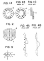
- Figure 1A shows in the form of a circular phase belt array a two-pole three-phase full-pitch type electric rotary machine on the basis of which a linear motor is constructed.
- the arrangement illustrated comprises six pairs of radially superposed phase belts U, V and W having equal phase belt spans of 60° arranged in a circle to form a circular phase belt array.
- the radially inner phase belts U, V and W designated by the reference numeral 1 represent top coil sides included in the same respectively while the radially outer phase belts U, V and W designated by the reference numeral 2 represent bottom coil sides included in the same respectively.
- Figure 1B In order to construct a primary winding of a linear motor, the arrangement of Figures 1A has been previously split as shown in Figure 1B.
- the phase belt U for the top coil sides belonging to the phase U and corresponding to the one pole is radially split from the adjacent phase belt W belonging to the phase W and corresponding to the other pole, and the phase belts U, V and W corresponding to the one pole and circumferentially split into the top and bottom coil sides until the phase belt W belonging to the phase W and corresponding to the one pole is radially split from the adjacent phase belt U belonging to the phase U and corresponding to the other pole.
- phase belt array is developed so that the phase belts U, V and W for the top coil sides and those for the bottom coil sides are developed into a linear form with the radially superposed phase belts U,-V and W corresponding to the other pole.
- Figure 1C shows the resulting structure which illustrates a conventional primary winding of a linear motor.
- the single layer wound phase belts U, V and W circumferentially split from each other are located on both end portions of the linear structure respectively and the double layers wound phase belts U, V and W are put on the intermediate portion thereof with the respective phase belts U and W for the top and bottom coil sides forming both ends of the linear structure.
- a single coil side located in each of integral slots (not shown) disposed on a primary linear core 3 and included in each of the phase belts located on either of the end portions thereof is connected via a diamond end construction of a bottom or top coil side disposed in a correspondings slot included in that phase belt belonging to the same phase as the firstmentioned phase belt, in accordance with whether the single coil side has be initially called “top” or "bottom".
- the coil side included in the phase belt U located on the end of the primary case 3 is connected to a corresponding bottom coils side included in the phase belt U located on the intermediate portion. This is because that single coil side has been initially called "top”.
- FIG 3 wherein the axis of ordinates represents an amplitude of accurent and the axis of abscissas represents time, there is shown a U, a V- and a W-phase sinusoidal alternating current flowing through the primary winding of three phase linear motors such as the arrangement illustrated in Figures 1C or 2.
- a time point T is also shown at which the V-phase current has a null instantaneous magnitude while the U and W phase currents are equal in instantaneous magnitude and opposite in sense to each object.
- the arrangement shown in Figure 1C or 2 has an instantaneous current distribution shown in Figure 4A wherein the axis of ordinattes represents a position of the phase belt and the axis of abscissas represents an amplitude of the current.
- the position of the phase belt is measured along the linear core 3 shown in Figure 2 or a linear array of the phase belts shown in Figure 1C starting with the upper end thereof as viewed in Figure 2 or Figure 1C.
- Figure 4B shows a magnetomotive force distribution resulting from the instantaneous current distribution illustrated in Figure 4A.
- the axis of ordinaties has the same meaning as that shown in Figure 4A and the axis of abscissas represents an amplitude of the magnetomotive force.
- the present invention contemplates to eliminate the disadvantage of the prior art practice as described above by changing the manner in which the arrangement of Figure lA is split.
- the phase belts belonging to any pair of adjacent phases in the circular array of Figure 1A are radially split along a boundary therebetween.
- the phase belt U belonging to the phase U is radially split from the phase belt W belonging to the phase W adjacent to the phase U along a boundary therebetween as shown in Figure 5A.
- Figure 5B shows the resulting structure.
- the primary linear winding is of the double layer type and required to be formed of a plurality of different types of coils.
- phase belts U and W are equal in instantaneous magnitude to each other but the phase belts U and W located at both ends of the linear core respectively are opposite in sense of the current to the phase belts U and W located on the middle portion thereof.
- the magnetomotive force distribution has a waveform of a magnatomotive force very close to a two-pole sinusoidal waveform. This means that an associated secondary stationary electrical conductor is applied with a travelling magnetomotive force having a waveform very close to the two-pole sinusoidal waveform. Thus the resulting thrust characteristic is excellent.
- one phase belt belonging to any selected ane of the three phases of the system in the circular phase belt array of Figure 1A is radially split so as to be circumferentially halved as shown in Figure 7A.
- phase belt array thus split is developed into a linear form.
- a linear phase belt away shown in Figure 7B is of the double layer type as that shown in Figure 5B and also required to be formed of a plurality of different types of coils.
- a corresponding magnetomotive force distribution is shown at solid line a in Figure 8B wherein the axes of ordinates and abscisas are identical in meaning to those shown in Figure 4B. While the magnetomotive force distribution lies only on the postive side of the axis of ordinates.
- a magnetomotive force waveform very close to a two-pole sinusoidal waveform can be provided as shown at dotted and dashed line c in Figure 8B by removing a rectangular waveform b extended throughout the entire length of the linear phase belt away as shown at dotted line b in Figure 8B.
- a primary winding of a linear motor is constructed in the similar manner that, in a phase belt away expressed by a corresponding two-pole, three-phase, full pitch type electric rotary machine two phase belts belonging to any pair of adjacent phases of the system are radially split from each other along a boundary therebetween and the phase belt away is developed into a linear form.
- one phase belt belonging to any of the three phases of the system may be radially split so as to be circumferentially halved and the phase belt array is developed into a linear form.
- the resulting linear motors are excellent in thrust characteristic.
Landscapes
- Engineering & Computer Science (AREA)
- Power Engineering (AREA)
- Physics & Mathematics (AREA)
- Chemical & Material Sciences (AREA)
- Combustion & Propulsion (AREA)
- Electromagnetism (AREA)
- Linear Motors (AREA)
Applications Claiming Priority (4)
| Application Number | Priority Date | Filing Date | Title |
|---|---|---|---|
| JP12968/84 | 1984-01-26 | ||
| JP1296884A JPS60160365A (ja) | 1984-01-26 | 1984-01-26 | リニアモ−タ |
| JP12967/84 | 1984-01-26 | ||
| JP1296784A JPS60160364A (ja) | 1984-01-26 | 1984-01-26 | リニアモ−タ |
Publications (3)
| Publication Number | Publication Date |
|---|---|
| EP0152222A2 true EP0152222A2 (de) | 1985-08-21 |
| EP0152222A3 EP0152222A3 (en) | 1986-07-30 |
| EP0152222B1 EP0152222B1 (de) | 1991-06-12 |
Family
ID=26348665
Family Applications (1)
| Application Number | Title | Priority Date | Filing Date |
|---|---|---|---|
| EP19850300565 Expired EP0152222B1 (de) | 1984-01-26 | 1985-01-28 | Linearmotor |
Country Status (2)
| Country | Link |
|---|---|
| EP (1) | EP0152222B1 (de) |
| DE (1) | DE3583154D1 (de) |
Family Cites Families (3)
| Publication number | Priority date | Publication date | Assignee | Title |
|---|---|---|---|---|
| US2648807A (en) * | 1948-12-01 | 1953-08-11 | Siemens Ag | Mechanically controllable induction machine |
| CH503415A (fr) * | 1968-12-20 | 1971-02-15 | Merlin Gerin | Moteur à induction linéaire |
| DE3202958C2 (de) * | 1982-01-29 | 1986-06-05 | Siemens AG, 1000 Berlin und 8000 München | Dreiphasige Wicklung in Stern-Dreieck-Mischschaltung für eine elektrische Maschine |
-
1985
- 1985-01-28 DE DE8585300565T patent/DE3583154D1/de not_active Expired - Lifetime
- 1985-01-28 EP EP19850300565 patent/EP0152222B1/de not_active Expired
Also Published As
| Publication number | Publication date |
|---|---|
| EP0152222A3 (en) | 1986-07-30 |
| DE3583154D1 (de) | 1991-07-18 |
| EP0152222B1 (de) | 1991-06-12 |
Similar Documents
| Publication | Publication Date | Title |
|---|---|---|
| US4110646A (en) | AC synchronous motor having an axially laminated rotor | |
| EP1153470B1 (de) | Doppeltgespeiste bürstenlose induktionsmaschinen mit doppelstab-käfiglaufer. | |
| US6570290B2 (en) | Single layer interspersed concentric stator winding apparatus and method | |
| US8258665B2 (en) | Motor winding | |
| US4393344A (en) | Squirrel cage induction motors | |
| US4338534A (en) | Pole-amplitude modulation, pole-changing electric motors and generators | |
| US5654602A (en) | Generator winding | |
| JP2011152000A (ja) | 回転電機 | |
| US20220286006A1 (en) | Motor | |
| EP0018835B1 (de) | Pol-umschaltbare elektrische Motoren und Generatoren mit Pol-Amplitude-Modulation | |
| US3421034A (en) | Single-phase induction electric motor | |
| JP4177462B2 (ja) | 回転電気装置用の2個の切り込み面内への巻線方法 | |
| US20050073207A1 (en) | Electric motor windings | |
| KR100454456B1 (ko) | 회전전기의전기자권선패턴 | |
| RU2050666C1 (ru) | 3/1-фазная электромашинная совмещенная обмотка | |
| US4780634A (en) | Alternating-current electrical generators | |
| EP0152222A2 (de) | Linearmotor | |
| US4321496A (en) | Discoidal winding coil structure for axial gap dynamoelectric machines | |
| GB2031660A (en) | Pole changing induction electrical machines | |
| SU1539902A1 (ru) | Трехфазна обмотка совмещенной электрической машины | |
| US2773208A (en) | Ring winding for electrical machines | |
| CN1038800C (zh) | 异步电动机转子绕组的叠加联结法 | |
| CA1139345A (en) | Multi speed polyphase motor arrangement | |
| EP0700143A2 (de) | Wicklung einer Wechselstrommaschine | |
| SU1098073A2 (ru) | Трехфазна совмещенна обмотка электрической машины переменного тока |
Legal Events
| Date | Code | Title | Description |
|---|---|---|---|
| PUAI | Public reference made under article 153(3) epc to a published international application that has entered the european phase |
Free format text: ORIGINAL CODE: 0009012 |
|
| AK | Designated contracting states |
Designated state(s): DE FR GB |
|
| PUAL | Search report despatched |
Free format text: ORIGINAL CODE: 0009013 |
|
| AK | Designated contracting states |
Kind code of ref document: A3 Designated state(s): DE FR GB |
|
| 17P | Request for examination filed |
Effective date: 19861215 |
|
| 17Q | First examination report despatched |
Effective date: 19890612 |
|
| GRAA | (expected) grant |
Free format text: ORIGINAL CODE: 0009210 |
|
| AK | Designated contracting states |
Kind code of ref document: B1 Designated state(s): DE FR GB |
|
| REF | Corresponds to: |
Ref document number: 3583154 Country of ref document: DE Date of ref document: 19910718 |
|
| REG | Reference to a national code |
Ref country code: GB Ref legal event code: 727 |
|
| ET | Fr: translation filed | ||
| REG | Reference to a national code |
Ref country code: GB Ref legal event code: 727A |
|
| REG | Reference to a national code |
Ref country code: GB Ref legal event code: 727A |
|
| PLBE | No opposition filed within time limit |
Free format text: ORIGINAL CODE: 0009261 |
|
| STAA | Information on the status of an ep patent application or granted ep patent |
Free format text: STATUS: NO OPPOSITION FILED WITHIN TIME LIMIT |
|
| 26N | No opposition filed | ||
| REG | Reference to a national code |
Ref country code: GB Ref legal event code: 727B |
|
| REG | Reference to a national code |
Ref country code: GB Ref legal event code: SP |
|
| PGFP | Annual fee paid to national office [announced via postgrant information from national office to epo] |
Ref country code: GB Payment date: 19930118 Year of fee payment: 9 |
|
| PGFP | Annual fee paid to national office [announced via postgrant information from national office to epo] |
Ref country code: FR Payment date: 19930122 Year of fee payment: 9 |
|
| PGFP | Annual fee paid to national office [announced via postgrant information from national office to epo] |
Ref country code: DE Payment date: 19930209 Year of fee payment: 9 |
|
| PG25 | Lapsed in a contracting state [announced via postgrant information from national office to epo] |
Ref country code: GB Effective date: 19940128 |
|
| GBPC | Gb: european patent ceased through non-payment of renewal fee |
Effective date: 19940128 |
|
| PG25 | Lapsed in a contracting state [announced via postgrant information from national office to epo] |
Ref country code: FR Effective date: 19940930 |
|
| PG25 | Lapsed in a contracting state [announced via postgrant information from national office to epo] |
Ref country code: DE Effective date: 19941001 |
|
| REG | Reference to a national code |
Ref country code: FR Ref legal event code: ST |