EP0152069B1 - Magnetic resonance imaging system - Google Patents
Magnetic resonance imaging system Download PDFInfo
- Publication number
- EP0152069B1 EP0152069B1 EP85101309A EP85101309A EP0152069B1 EP 0152069 B1 EP0152069 B1 EP 0152069B1 EP 85101309 A EP85101309 A EP 85101309A EP 85101309 A EP85101309 A EP 85101309A EP 0152069 B1 EP0152069 B1 EP 0152069B1
- Authority
- EP
- European Patent Office
- Prior art keywords
- signal
- gain
- magnetic field
- projection data
- signal processing
- Prior art date
- Legal status (The legal status is an assumption and is not a legal conclusion. Google has not performed a legal analysis and makes no representation as to the accuracy of the status listed.)
- Expired
Links
Images


Classifications
-
- G—PHYSICS
- G01—MEASURING; TESTING
- G01R—MEASURING ELECTRIC VARIABLES; MEASURING MAGNETIC VARIABLES
- G01R33/00—Arrangements or instruments for measuring magnetic variables
- G01R33/20—Arrangements or instruments for measuring magnetic variables involving magnetic resonance
- G01R33/28—Details of apparatus provided for in groups G01R33/44 - G01R33/64
- G01R33/32—Excitation or detection systems, e.g. using radio frequency signals
- G01R33/36—Electrical details, e.g. matching or coupling of the coil to the receiver
- G01R33/3621—NMR receivers or demodulators, e.g. preamplifiers, means for frequency modulation of the MR signal using a digital down converter, means for analog to digital conversion [ADC] or for filtering or processing of the MR signal such as bandpass filtering, resampling, decimation or interpolation
-
- G—PHYSICS
- G01—MEASURING; TESTING
- G01R—MEASURING ELECTRIC VARIABLES; MEASURING MAGNETIC VARIABLES
- G01R33/00—Arrangements or instruments for measuring magnetic variables
- G01R33/20—Arrangements or instruments for measuring magnetic variables involving magnetic resonance
- G01R33/44—Arrangements or instruments for measuring magnetic variables involving magnetic resonance using nuclear magnetic resonance [NMR]
- G01R33/48—NMR imaging systems
- G01R33/58—Calibration of imaging systems, e.g. using test probes, Phantoms; Calibration objects or fiducial markers such as active or passive RF coils surrounding an MR active material
Definitions
- the present invention relates to a magnetic resonance imaging (MRI) system.
- MRI magnetic resonance imaging
- a magnetic resonance (MR) signal of an object under inspection is detected by making use of a magnetic resonance (MR) phenomenon.
- the detected data is subjected to an image reconstruction process by computed tomography (CT), and then programmed into a computed tomogram as a density distribution of specific atomic nuclei and a relaxation time constant distribution of a specific cross section of the object.
- CT computed tomography
- the MRI system was initially developed for diagnosis in the medical field, but recently it's application for nondestructive inspection has been studied.
- an extremely uniform static magnetic field Ho is applied to an object under inspection, e.g., a human body P, in the direction of a z axis in Fig. 1.
- a linear magnetic gradient field Gz is superposed on the static magnetic field Ho by a pair of inclined magnetic field coils Za and Zb.
- the direction of the magnetic field is directed along the z axis, and its intensity is gradually increased or decreased along the z axis in a linear fashion.
- the atomic nucleus resonates with the static magnetic field Ho at an angular frequency wo as . given below where y is a gyromagnetic ratio peculiar to the atomic nucleus, and its value depends on the type of atomic nucleus under study.
- a pair of transmitting coils Ta and Tb applies (to the human body P) a rotating magnetic field HI at an angular frequency wo to resonate only a specific atomic nucleus, viz., the angular frequency ⁇ o for the specific atomic nucleus.
- the MR phenomenon is caused only in a plane selected as an isomagnetic plane with a specific intensity, by the magnetic gradient field Gz, for example, an x - y plane in Fig. 1.
- the plane is a cross section which is used to obtain a tomogram of a slice S (which actually has a given thickness).
- the MR phenomenon is observed as a free induction decay (FID) signal, through the receiving coils Ra and Rb. This signal is then Fourier transformed to have a single spectrum on the angular frequency ⁇ o of the specific atomic nucleus.
- FID free induction decay
- a magnetic gradient field Gxy with a linear slope of the magnetic field along an x' axis (rotated by angle 0 from the x axis on the x - y plane), as shown in Fig. 2, is superposed onto the static magnetic field Ho.
- the magnetic gradient field Gxy is such that its direction is in parallel with the z axis and its intensity gradually increases or decreases in thex' direction in a linear fashion.
- the magnetic gradient field Gxy causes linear and equal magnetic lines El to En with different values to be formed in the slice S of the human body P.
- the rotating angular frequencies wo, of the nuclear spin of the specific atomic nuclei on the isomagnetic lines El to En, take values dependent on the intensities of the magnetic fields, which are each defined by the formula (1).
- Signals DI to Dn as FID signals must be generated by the magnetic fields on the isomagnetic lines El to En.
- the amplitudes of the signals Dl to Dn are proportional to the density of the nuclear spins of the specific atomic nuclei, viz., the density of the specific atomic nuclei, on the isomagnetic lines El to En passing through the slice S.
- these signals DI to Dn are not observed individually, but in the form of a composite FID signal Fd as the sum of these signals DI to Dn.
- the projection data (one dimensional image) Pd to the x' axis of the slice S is obtained by Fourier transforming the composite signal Fd.
- the projection data is collected for each predetermined angle, thereby obtaining projection data in each direction of the x - y plane.
- the projection data is used for the image reconstruction, to form a computed tomogram.
- the magnetic gradient fields Gx and Gy in the x and y directions, respectively are formed by pairs of magnetic gradient field coils. These magnetic gradient fields Gx and Gy are combined to form a composite magnetic gradient field Gxy. One of the two pairs of magnetic gradient field coils is controlled to change the ratio of the magnetic gradient field Gx to that of the magnetic gradient field Gy. Then, the inclining direction of the composite magnetic field Gxy is changed.
- prior art document EP-A-0 042 256 describes an NMR apparatus having means for compensating projection signals: A pair of standard signal sources made of a material containing a specified atomic nucleus are disposed in a coil holder so as to compensate the projection signal. The functions of this compensating means and reconstructing means used can be performed by an electronic computer.
- the present invention provides a magnetic resonance imaging system comprising: coil means disposed around an imaging area in which an object under inspection is placed; signal detecting means which cooperates with said coil means to cause a magnetic resonance phenomenon in specific atomic nuclei in said imaging area and to detect magnetic resonance (MR) signals from a predetermined cross section in said imaging area; signal processing means for obtaining said projection data by applying a predetermined process to the MR signal detected by said signal detecting means; image reconstructing means for obtaining image data based on the MR data on said cross section by applying an image reconstructing process to the projection data obtained by said signal processing means; a reference sample made of material including said specific atomic nuclei and disposed contiguous to said object and in said imaging area; and detecting means for obtaining a value of the projection data on said reference sample from the output of said signal processing means; said magnetic resonance imaging system being characterized by: gain adjusting means for controlling one of said detecting means, said signal processing means and said image reconstructing means according to the value obtained by said detecting means, thereby to control a
- a reference sample made of material containing predetermined atomic nuclei to be tomographed is placed on the side of an object under inspection in an imaging field of an MR image (area to be tomographed).
- the magnitude of the projection data of the reference sample is detected.
- a substantial gain in an MR signal receiving processing system is adjusted according to the magnitude. Therefore, the MR data on the reference sample can be kept at a fixed value irrespective of the differentials of the objects.
- a first coil assembly 1 consisting of four air-core coils for generating a uniform static magnetic field Ho in an imaging area, is energized by an energizing source 2.
- the second coil 3 corresponds to the coils Za and Zb shown in Fig. 1, for example.
- An oscillator 7 generates an exciting signal for exciting a slice to cause an MR phenomenon.
- the exciting signal is applied to a transmitter/receiver 8, so that a rotating magnetic field at a rotating angular frequency wo is applied to the imaging area, through a probe head 9, thereby causing the MR phenomenon.
- An MR signal resulting from the MR phenomenon is received by the transmitter/ receiver 8 through the probe head 9.
- the probe head 9 corresponds to the transmission coils Ta and Tb and the receiving coils Ra and Rb shown in Fig. 1.
- the MR signal received by the transmitter/ receiver 8 is amplified and detected by an amplifier/detector 10, and is then applied to a data processing device 11.
- the data processing device 11 controls the operation of the second energizing sources 4 and 6.
- the data processing device 11 includes a means for A/D converting the applied MR signal, a means for Fourier transforming the digitized signal by a DFT (discrete Fourier transform), for example, an FFT (fast Fourier transform), thereby to have the projection data on the MR data, and a means for image processing the projection data to reconstruct an image.
- the MR image reconstructed by the data processing device 11 is visually displayed by a display at a console 12.
- a human body P lies on the table 13.
- a reference sample S1 is secured to the under side of that portion of a table board 14 which supports the torso of the human body P.
- Another reference sample S2 is set on the back side of a head rest 15 for supporting the head of the human body P.
- These reference samples S1 and S2 are used for providing reference data, which is used to obtain the optimum gain in the receiving system.
- the reference samples S1 and S2 may be made of material containing a nuclear spin system emitting an MR signal at the same frequency as that of the atomic nuclei to be tomographed, viz., usually the tomographed atomic nuclei has a known, stable density. If the photographed atomic nuclei are hydrogen atomic nuclei, the reference samples S1 and S2 may be rubber or water in a proper container.
- FIG. 5A A cross section along line I - I shown in Fig. 4A is shown in Fig. 5A, and the projection data distributed on the cross section in the y direction is illustrated in Fig. 5B.
- the projection data consists of two components PD1 and PD2.
- PD1 is the component on the patient P, and P02 the component on the reference sample S1.
- the position data i.e., the angular frequency wo of PD1 and pD2
- the data components on these samples can be discriminated in accordance with the position data (i.e., the angular frequencies of these components) which has been obtained by y-axis projection.
- Fig. 6 shows an arrangement of a receiving processing system of the MRI system of this embodiment.
- An MR signal on the human body P and the reference sample S1 that is, a FID signal, is detected by the probe head 9.
- the MR signal is then tuned by a tuning circuit composed of the probe head 9 and a tuning capacitor C in the transmitter/receiver 8, and amplified by an amplifier 10a in the amplifier/detector 10, and further detected by a detector 10b of the amplifier/ detector 10.
- the MR signal is passed through an A/D converter 11a in the data processing device 11, and input to a central processing unit (CPU) 11b of the data processing device 11.
- the digitized MR signal is subjected to the DFT, usually the FFT, by the CPU 11b, and is transformed into the projection data.
- the image reconstruction processing (and other necessary processings) are performed on the basis of the projection data collected in many directions.
- the Q of the probe head 9 changes with differentials of the human bodies P, as mentioned above.
- An amplification of the tuning circuit made up of the probe head 9 and the capacitor C changes, and a magnitude of the projection data changes.
- a quantitative diagnosis based on the image finally formed is impossible.
- a magnitude of the projection data PD2 of the reference sample S1 changes correspondingly.
- the projection data PD2 of the reference sample S1 can easily be separated from the projection data PD1 of the human body P by an angular frequency, as already mentioned.
- the magnitude of the projection data PD2 changes with respect to a value preset according to a proper magnitude for the reference sample S1.
- the CPU 11 b detects this and feeds it back to the receiving side.
- the amplifier 10a is constructed with a variable gain amplifier.
- a gain in the amplifier 10a is controlled, by the CPU 11 b, according to a deviation of the magnitude of the projection data PD2 from the preset value, so that the deviation is zero (that is, the magnitude of the projection data PD2 is equal to the preset value).
- the console 12 for system operation connected to the CPU 11b is also used for the system operation through the CPU 11b in addition to the image display by the output from the CPU 11 b.
- the projection data PD2 of the reference sample S1 is kept at a fixed value irrespective of the differentials of the human body P. Even for different human bodies P, the MR signals derived from the same portions take the same values on the MR image. Thus, the MR image data can be obtained as absolute image data.
- the tomographing can always be made at a proper receiving gain for the reference sample. Accordingly, the MR image data can be obtained from the absolute data, not the relative data. Therefore, the MR image data can be qualitatively and clinically evaluated.
- the MR data e.g. a proton density
- the MR data e.g. a proton density
- the MR data can be calibrated by this value, thereby ensuring further reliable MR image data.
- the feedback is made from the CPU 11 b to the detector 10b, to change a detector gain.
- the feedback is made from the CPU 11 b to the A/C converter 11a, to change a converting gain of the A/C converter 11 a (the magnitude of the quantitiz- ing step, i.e., weighting of the digital values) and to substantially change a gain of the receiving system.
- an MR signal is tuned by the tuning circuit, amplified by the amplifier 10a (in this case, a variable gain is not required), and detected and extracted by the detector 10b.
- the MR signal is inputted to the CPU 11 b via the A/C converter 11 a.
- a correction coefficient such that the magnitude of the projection data is used as a preset value, is obtained. Correction by the correction coefficient is applied to the projection data (e.g. PD1) of the human body P.
- the feed forward control with an open loop is realized by only the digital processing.
- the reference sample may be provided at any place if it is located on the side of the object under inspection and in the imaging area.
- the reference sample is preferably placed on an object support member (such as a table), has an appropriate length, and is directed in the axial direction of the object.
Description
- The present invention relates to a magnetic resonance imaging (MRI) system.
- In the MRI system, a magnetic resonance (MR) signal of an object under inspection is detected by making use of a magnetic resonance (MR) phenomenon. The detected data is subjected to an image reconstruction process by computed tomography (CT), and then programmed into a computed tomogram as a density distribution of specific atomic nuclei and a relaxation time constant distribution of a specific cross section of the object. The MRI system was initially developed for diagnosis in the medical field, but recently it's application for nondestructive inspection has been studied.
- In order to obtain a tomogram at a specific position of an object in the MRI system, an extremely uniform static magnetic field Ho is applied to an object under inspection, e.g., a human body P, in the direction of a z axis in Fig. 1. A linear magnetic gradient field Gz is superposed on the static magnetic field Ho by a pair of inclined magnetic field coils Za and Zb. In the gradient field Gz, the direction of the magnetic field is directed along the z axis, and its intensity is gradually increased or decreased along the z axis in a linear fashion. Under this condition, there are a number ofx-y isomagnetic planes in parallel to each other and perpendicular to the z axis.
- The atomic nucleus resonates with the static magnetic field Ho at an angular frequency wo as . given below

- As mentioned above, when the human body P is under the static magnetic field Ho and the magnetic gradient field Gz, a pair of transmitting coils Ta and Tb applies (to the human body P) a rotating magnetic field HI at an angular frequency wo to resonate only a specific atomic nucleus, viz., the angular frequency ωo for the specific atomic nucleus.
- When the human body P is subjected to such magnetic fields, the MR phenomenon is caused only in a plane selected as an isomagnetic plane with a specific intensity, by the magnetic gradient field Gz, for example, an x - y plane in Fig. 1. The plane is a cross section which is used to obtain a tomogram of a slice S (which actually has a given thickness).
- The MR phenomenon is observed as a free induction decay (FID) signal, through the receiving coils Ra and Rb. This signal is then Fourier transformed to have a single spectrum on the angular frequency ωo of the specific atomic nucleus. To reconstruct the tomograph as a computed tomogram, it is necessary to have projection information in as many directions in the x - y plane as in the slice S.
- To obtain the projection information, after the slice S is excited to cause the MR phenomenon, a magnetic gradient field Gxy with a linear slope of the magnetic field along an x' axis (rotated by angle 0 from the x axis on the x - y plane), as shown in Fig. 2, is superposed onto the static magnetic field Ho. As shown, the magnetic gradient field Gxy is such that its direction is in parallel with the z axis and its intensity gradually increases or decreases in thex' direction in a linear fashion. The magnetic gradient field Gxy causes linear and equal magnetic lines El to En with different values to be formed in the slice S of the human body P. The rotating angular frequencies wo, of the nuclear spin of the specific atomic nuclei on the isomagnetic lines El to En, take values dependent on the intensities of the magnetic fields, which are each defined by the formula (1). Signals DI to Dn as FID signals must be generated by the magnetic fields on the isomagnetic lines El to En. The amplitudes of the signals Dl to Dn are proportional to the density of the nuclear spins of the specific atomic nuclei, viz., the density of the specific atomic nuclei, on the isomagnetic lines El to En passing through the slice S. Actually, these signals DI to Dn are not observed individually, but in the form of a composite FID signal Fd as the sum of these signals DI to Dn. The projection data (one dimensional image) Pd to the x' axis of the slice S is obtained by Fourier transforming the composite signal Fd. By successively rotating the x' axis in the x - y plane (by changing 0), the projection data is collected for each predetermined angle, thereby obtaining projection data in each direction of the x - y plane. The projection data is used for the image reconstruction, to form a computed tomogram.
- The rotation of the magnetic gradient field Gxy, that is, the change of 0, will be described.
- The magnetic gradient fields Gx and Gy in the x and y directions, respectively are formed by pairs of magnetic gradient field coils. These magnetic gradient fields Gx and Gy are combined to form a composite magnetic gradient field Gxy. One of the two pairs of magnetic gradient field coils is controlled to change the ratio of the magnetic gradient field Gx to that of the magnetic gradient field Gy. Then, the inclining direction of the composite magnetic field Gxy is changed.
- When the human body P is placed between the receiving coils Ra and Rb, a quality factor (Q) of each of these coils is changed, as a matter of course. The change in Q depends on features of the human body P, for example, adult or child, fat or skinny, man or woman, the physical configuration of the human body P, large or small, etc. As a result, it is equivalent to the change in the gain of the receiving system.
- When Q is changed, the density of specific atomic nuclei on the image (e.g., a proton density) inevitably changes depending on the differentials of the human body P. This fact rejects a quantitative evaluation of the MR image data.
- Prior art document EP-A-0 105 220 (filing date 07.09.1983; priority date 22.09.1982) Article 54(3) EPC discloses an NMR imaging apparatus for generating images of an object under investigation. In this apparatus calibrating bodies of known ingredients are arranged inside magnet field coils. By performing a simultaneous measuring of a layer of the object under investigation and of the calibrating body a standardisation of received signals is rendered possible.
- Further, prior art document EP-A-0 042 256 describes an NMR apparatus having means for compensating projection signals: A pair of standard signal sources made of a material containing a specified atomic nucleus are disposed in a coil holder so as to compensate the projection signal. The functions of this compensating means and reconstructing means used can be performed by an electronic computer.
- It is an object of the present invention to provide a magnetic resonance imaging system which can keep an optimum gain in a receiving system irrespective of the differentials of the object under inspection, thus eliminating variation in the MR data due to the differentials of the object, and enabling an absolute evaluation of the MR image.
- The present invention provides a magnetic resonance imaging system comprising: coil means disposed around an imaging area in which an object under inspection is placed; signal detecting means which cooperates with said coil means to cause a magnetic resonance phenomenon in specific atomic nuclei in said imaging area and to detect magnetic resonance (MR) signals from a predetermined cross section in said imaging area; signal processing means for obtaining said projection data by applying a predetermined process to the MR signal detected by said signal detecting means; image reconstructing means for obtaining image data based on the MR data on said cross section by applying an image reconstructing process to the projection data obtained by said signal processing means; a reference sample made of material including said specific atomic nuclei and disposed contiguous to said object and in said imaging area; and detecting means for obtaining a value of the projection data on said reference sample from the output of said signal processing means; said magnetic resonance imaging system being characterized by: gain adjusting means for controlling one of said detecting means, said signal processing means and said image reconstructing means according to the value obtained by said detecting means, thereby to control a substantial gain in a processing system including said signal detecting means, said signal processing means and said image reconstructing means.
- In the magnetic resonance imaging system of the present invention, a reference sample made of material containing predetermined atomic nuclei to be tomographed, is placed on the side of an object under inspection in an imaging field of an MR image (area to be tomographed). When collecting projection data by the detection of the MR signal, the magnitude of the projection data of the reference sample is detected. A substantial gain in an MR signal receiving processing system is adjusted according to the magnitude. Therefore, the MR data on the reference sample can be kept at a fixed value irrespective of the differentials of the objects.
- This invention can be more fully understood from the following detailed description when taken in conjunction with the accompanying drawings, in which:
- Figs. 1 and 2 show views useful in explaining the principles of the magnetic resonance imaging;
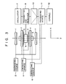
- Fig. 3 is a block diagram showing an arrangement of a magnetic resonance imaging system which is an embodiment of the present invention;
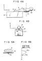
- Figs. 4A and 4B show views illustrating a table of the MRI system on which an object under inspection lies;
- Figs. 5A and 5B show respectively a cross .section taken on line I - I of Fig. 4A useful in explaining the operation of the MRI system, and the projection data collected traversing the cross section;
- Fig. 6 is a block diagram showing an arrangement of a receiving processing system of the MRI system; and
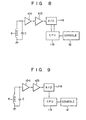
- Figs. 7 to 9 are respectively block diagrams of major portions of different embodiments of a MRI system according to the present invention.
- Reference is made to Fig. 3 illustrating an arrangement of an embodiment of an MRI system according to the present invention. In the figure, a first coil assembly 1 consisting of four air-core coils for generating a uniform static magnetic field Ho in an imaging area, is energized by an
energizing source 2. Asecond coil 3 for generating a magnetic gradient field Gz which is superposed on the static magnetic field Ho at the imaging area, is energized by a secondenergizing source 4. Thesecond coil 3 corresponds to the coils Za and Zb shown in Fig. 1, for example. Athird coil 5 for generating a magnetic gradient field Gxy, which is superposed on the static magnetic field Ho in the imaging area, is energized by a thirdenergizing source 6. Anoscillator 7 generates an exciting signal for exciting a slice to cause an MR phenomenon. The exciting signal is applied to a transmitter/receiver 8, so that a rotating magnetic field at a rotating angular frequency wo is applied to the imaging area, through aprobe head 9, thereby causing the MR phenomenon. An MR signal resulting from the MR phenomenon is received by the transmitter/receiver 8 through theprobe head 9. Theprobe head 9 corresponds to the transmission coils Ta and Tb and the receiving coils Ra and Rb shown in Fig. 1. The MR signal received by the transmitter/receiver 8 is amplified and detected by an amplifier/detector 10, and is then applied to adata processing device 11. Thedata processing device 11 controls the operation of the second energizingsources data processing device 11 includes a means for A/D converting the applied MR signal, a means for Fourier transforming the digitized signal by a DFT (discrete Fourier transform), for example, an FFT (fast Fourier transform), thereby to have the projection data on the MR data, and a means for image processing the projection data to reconstruct an image. The MR image reconstructed by thedata processing device 11 is visually displayed by a display at aconsole 12. - A table of the MRI system on which a human body P lies as the object under inspection will be described in detail.
- In Figs. 4A and 4B, a human body P lies on the table 13. A reference sample S1 is secured to the under side of that portion of a
table board 14 which supports the torso of the human body P. Another reference sample S2 is set on the back side of ahead rest 15 for supporting the head of the human body P. These reference samples S1 and S2 are used for providing reference data, which is used to obtain the optimum gain in the receiving system. The reference samples S1 and S2 may be made of material containing a nuclear spin system emitting an MR signal at the same frequency as that of the atomic nuclei to be tomographed, viz., usually the tomographed atomic nuclei has a known, stable density. If the photographed atomic nuclei are hydrogen atomic nuclei, the reference samples S1 and S2 may be rubber or water in a proper container. - A cross section along line I - I shown in Fig. 4A is shown in Fig. 5A, and the projection data distributed on the cross section in the y direction is illustrated in Fig. 5B.
- As Figs. 5A and 5B show, the projection data consists of two components PD1 and PD2. PD1 is the component on the patient P, and P02 the component on the reference sample S1. When the sample S1 is placed beside the patient P, not within the body or in a recess of the body, there exists a projection angle, which can be used jointly with the position data (i.e., the angular frequency wo of PD1 and pD2) to distinguish the data components PD1 and PD2 from each other. When the samples S1 and S2 are put on the under side of the
board 14 and thehead rest 15, as shown in Figs. 4A and 4B, the data components on these samples can be discriminated in accordance with the position data (i.e., the angular frequencies of these components) which has been obtained by y-axis projection. - Fig. 6 shows an arrangement of a receiving processing system of the MRI system of this embodiment.
- An MR signal on the human body P and the reference sample S1, that is, a FID signal, is detected by the
probe head 9. The MR signal is then tuned by a tuning circuit composed of theprobe head 9 and a tuning capacitor C in the transmitter/receiver 8, and amplified by an amplifier 10a in the amplifier/detector 10, and further detected by a detector 10b of the amplifier/detector 10. The MR signal is passed through an A/D converter 11a in thedata processing device 11, and input to a central processing unit (CPU) 11b of thedata processing device 11. The digitized MR signal is subjected to the DFT, usually the FFT, by theCPU 11b, and is transformed into the projection data. In the usual tomographing, the image reconstruction processing (and other necessary processings) are performed on the basis of the projection data collected in many directions. With such a processing, however, the Q of theprobe head 9 changes with differentials of the human bodies P, as mentioned above. An amplification of the tuning circuit made up of theprobe head 9 and the capacitor C changes, and a magnitude of the projection data changes. As a result, a quantitative diagnosis based on the image finally formed is impossible. - In the present embodiment, however, when the amplification of the tuning circuit changes due to the differentials of the human bodies P, a magnitude of the projection data PD2 of the reference sample S1 (in tomographing the cross section along line I - I) changes correspondingly. The projection data PD2 of the reference sample S1 can easily be separated from the projection data PD1 of the human body P by an angular frequency, as already mentioned. The magnitude of the projection data PD2 changes with respect to a value preset according to a proper magnitude for the reference sample S1. the
CPU 11 b detects this and feeds it back to the receiving side. Specifically, the amplifier 10a is constructed with a variable gain amplifier. A gain in the amplifier 10a is controlled, by theCPU 11 b, according to a deviation of the magnitude of the projection data PD2 from the preset value, so that the deviation is zero (that is, the magnitude of the projection data PD2 is equal to the preset value). - Usually, it is sufficient to make the adjustment of one projection before the intended tomographing. If necessary, it may be done by interrupting the tomographing during the tomographing of a plurality of frames. The
console 12 for system operation connected to theCPU 11b, is also used for the system operation through theCPU 11b in addition to the image display by the output from theCPU 11 b. - As described above, the projection data PD2 of the reference sample S1 is kept at a fixed value irrespective of the differentials of the human body P. Even for different human bodies P, the MR signals derived from the same portions take the same values on the MR image. Thus, the MR image data can be obtained as absolute image data.
- As described above, the tomographing can always be made at a proper receiving gain for the reference sample. Accordingly, the MR image data can be obtained from the absolute data, not the relative data. Therefore, the MR image data can be qualitatively and clinically evaluated.
- In this case, if the MR data (e.g. a proton density) of the reference sample is known, the MR data (e.g. a proton density) can be calibrated by this value, thereby ensuring further reliable MR image data.
- Some modifications of the embodiments as mentioned above will be given. In Fig. 7, the feedback is made from the
CPU 11 b to the detector 10b, to change a detector gain. In Fig. 8, the feedback is made from theCPU 11 b to the A/C converter 11a, to change a converting gain of the A/C converter 11 a (the magnitude of the quantitiz- ing step, i.e., weighting of the digital values) and to substantially change a gain of the receiving system. - An example of the digital control to substantially change a gain in the receiving system, not the analog control as in the above-mentioned case, will be described referring to Fig. 9.
- In Fig. 9, an MR signal is tuned by the tuning circuit, amplified by the amplifier 10a (in this case, a variable gain is not required), and detected and extracted by the detector 10b. The MR signal is inputted to the
CPU 11 b via the A/C converter 11 a. In obtaining the projection data by the FFT in theCPU 11 b, from the projection data of the reference sample, a correction coefficient such that the magnitude of the projection data is used as a preset value, is obtained. Correction by the correction coefficient is applied to the projection data (e.g. PD1) of the human body P. Thus, in this example, the feed forward control with an open loop is realized by only the digital processing. - The reference sample may be provided at any place if it is located on the side of the object under inspection and in the imaging area. To make the reference sample effective irrespective of the location of the slice, the reference sample is preferably placed on an object support member (such as a table), has an appropriate length, and is directed in the axial direction of the object.
Claims (9)
Applications Claiming Priority (2)
| Application Number | Priority Date | Filing Date | Title |
|---|---|---|---|
| JP59023084A JPS60165951A (en) | 1984-02-10 | 1984-02-10 | Nuclear magnetic resonance imaging apparatus for diagnosis |
| JP23084/84 | 1984-02-10 |
Publications (3)
| Publication Number | Publication Date |
|---|---|
| EP0152069A2 EP0152069A2 (en) | 1985-08-21 |
| EP0152069A3 EP0152069A3 (en) | 1987-04-22 |
| EP0152069B1 true EP0152069B1 (en) | 1989-04-19 |
Family
ID=12100549
Family Applications (1)
| Application Number | Title | Priority Date | Filing Date |
|---|---|---|---|
| EP85101309A Expired EP0152069B1 (en) | 1984-02-10 | 1985-02-07 | Magnetic resonance imaging system |
Country Status (4)
| Country | Link |
|---|---|
| US (1) | US4665364A (en) |
| EP (1) | EP0152069B1 (en) |
| JP (1) | JPS60165951A (en) |
| DE (1) | DE3569614D1 (en) |
Cited By (1)
| Publication number | Priority date | Publication date | Assignee | Title |
|---|---|---|---|---|
| DE3923069A1 (en) * | 1989-07-13 | 1991-01-24 | Bruker Medizintech | METHOD AND DEVICE FOR CALIBRATING A HIGH-FREQUENCY FIELD STRENGTH IN A MEASURING SPACE OF A NUCLEAR SPIN TOMOGRAPH |
Families Citing this family (19)
| Publication number | Priority date | Publication date | Assignee | Title |
|---|---|---|---|---|
| JPS60222043A (en) * | 1984-04-20 | 1985-11-06 | 横河電機株式会社 | Diagnostic apparatus by nuclear magnetic resonance |
| DE3614142C2 (en) * | 1985-04-26 | 1996-03-28 | Toshiba Kawasaki Kk | Use of a material for diagnosis by nuclear magnetic resonance spectroscopy |
| US4703267A (en) * | 1985-07-17 | 1987-10-27 | Advanced Nmr Systems, Inc. | High dynamic range in NMR data acquisition |
| US4716368A (en) * | 1985-08-09 | 1987-12-29 | Picker International, Inc. | Magnetic resonance reconstruction and scanning techniques using known information, constraints, and symmetry relations |
| IL78096A (en) * | 1986-03-10 | 1990-04-29 | Elscint Ltd | Determining absolute image intensity in magnetic resonance systems |
| US4739268A (en) * | 1987-01-21 | 1988-04-19 | Kabushiki Kaisha Toshiba | RF pulse control system for a magnetic resonance imaging transmitter |
| US5284144A (en) * | 1989-11-22 | 1994-02-08 | The United States Of America As Represented By The Secretary Of The Dept. Of Health & Human Services | Apparatus for hyperthermia treatment of cancer |
| JPH05103768A (en) * | 1991-03-20 | 1993-04-27 | Hitachi Ltd | Magnetic resonance imaging method |
| IT1282664B1 (en) * | 1996-02-21 | 1998-03-31 | Bracco Spa | DEVICE FOR THE STANDARDIZATION OF THE SIGNAL INTENSITY IN THE TECHNIQUE OF IMAGE FORMATION WITH MAGNETIC RESONANCE |
| US6448770B1 (en) * | 2000-03-30 | 2002-09-10 | Koninklijke Philips Electronics, N.V. | Gain selection for magnetic resonance imaging and spectroscopy |
| JP4694713B2 (en) * | 2001-04-23 | 2011-06-08 | ジーイー・メディカル・システムズ・グローバル・テクノロジー・カンパニー・エルエルシー | RF pulse adjusting method and apparatus and magnetic resonance imaging apparatus |
| US6621433B1 (en) | 2001-06-22 | 2003-09-16 | Fonar Corporation | Adaptive dynamic range receiver for MRI |
| US6943548B1 (en) | 2001-06-22 | 2005-09-13 | Fonar Corporation | Adaptive dynamic range receiver for MRI |
| US6977502B1 (en) | 2002-11-04 | 2005-12-20 | Fonar Corporation | Configurable matrix receiver for MRI |
| GB2409724A (en) * | 2003-12-30 | 2005-07-06 | Adphil Ltd | NMR Leak Test |
| JP2007054214A (en) * | 2005-08-24 | 2007-03-08 | Hitachi Ltd | Magnetic resonance diagnostic apparatus |
| US10045712B2 (en) | 2012-02-02 | 2018-08-14 | Children's Hospital Medical Center | MRI transfer station and dock |
| EP3508129A1 (en) | 2012-02-02 | 2019-07-10 | Children's Hospital Medical Center | Mri transfer table assembly |
| US9625545B2 (en) | 2013-05-29 | 2017-04-18 | Childrens Hospital Medical Center | Faraday cage for MR imaging with accessory equipment |
Family Cites Families (4)
| Publication number | Priority date | Publication date | Assignee | Title |
|---|---|---|---|---|
| JPS6051056B2 (en) * | 1980-06-13 | 1985-11-12 | 株式会社東芝 | nuclear magnetic resonance apparatus |
| DE3235113A1 (en) * | 1982-09-22 | 1984-03-22 | Siemens AG, 1000 Berlin und 8000 München | DEVICE FOR GENERATING IMAGES OF AN EXAMINATION OBJECT WITH A MAGNETIC CORE RESONANCE |
| US4551678A (en) * | 1982-11-26 | 1985-11-05 | Morgan Tommie J | Phantom for nuclear magnetic resonance machine |
| US4585992A (en) * | 1984-02-03 | 1986-04-29 | Philips Medical Systems, Inc. | NMR imaging methods |
-
1984
- 1984-02-10 JP JP59023084A patent/JPS60165951A/en active Granted
-
1985
- 1985-02-07 EP EP85101309A patent/EP0152069B1/en not_active Expired
- 1985-02-07 DE DE8585101309T patent/DE3569614D1/en not_active Expired
- 1985-02-08 US US06/699,960 patent/US4665364A/en not_active Expired - Fee Related
Cited By (1)
| Publication number | Priority date | Publication date | Assignee | Title |
|---|---|---|---|---|
| DE3923069A1 (en) * | 1989-07-13 | 1991-01-24 | Bruker Medizintech | METHOD AND DEVICE FOR CALIBRATING A HIGH-FREQUENCY FIELD STRENGTH IN A MEASURING SPACE OF A NUCLEAR SPIN TOMOGRAPH |
Also Published As
| Publication number | Publication date |
|---|---|
| EP0152069A3 (en) | 1987-04-22 |
| DE3569614D1 (en) | 1989-05-24 |
| US4665364A (en) | 1987-05-12 |
| JPH0577419B2 (en) | 1993-10-26 |
| EP0152069A2 (en) | 1985-08-21 |
| JPS60165951A (en) | 1985-08-29 |
Similar Documents
| Publication | Publication Date | Title |
|---|---|---|
| EP0152069B1 (en) | Magnetic resonance imaging system | |
| US5485086A (en) | Continuous fluoroscopic MRI using spiral k-space scanning | |
| JP4544443B2 (en) | Field frequency lock system for magnetic resonance systems | |
| EP0932048B1 (en) | Localized shim coil for use in magnetic resonance imaging system | |
| US6507190B1 (en) | Method and apparatus for compensating polarizing fields in magnetic resonance imaging | |
| EP0430088A2 (en) | Method for in-vivo shimming | |
| EP2219023B1 (en) | Wideband magnetic resonance imaging apparatus and method | |
| EP0096487B1 (en) | Method and apparatus for monitoring movement of a body under nmr examination | |
| JPS59107245A (en) | Nuclear magnetic resonance method and its device | |
| EP0112663B1 (en) | Nuclear magnetic resonance methods and apparatus | |
| US4733183A (en) | Nuclear magnetic resonance methods and apparatus | |
| US4737714A (en) | Magnetic resonance spectroscopy | |
| JPH07508919A (en) | Frequency calibration method for MRI scanners | |
| EP0161366A2 (en) | Nuclear magnetic resonance methods and apparatus | |
| US6853190B2 (en) | Method and apparatus for magnetic resonance imaging with simultaneous measurement of two neighboring slices | |
| US6853193B2 (en) | Simultaneous MR data acquisition with multiple mutually desensitized RF coils | |
| US4646023A (en) | Nuclear magnetic resonance imaging | |
| US4789830A (en) | Determining absolute image intensity in magnetic resonance systems | |
| EP0217578B1 (en) | Nuclear magnetic resonance methods and apparatus | |
| US5015955A (en) | Magnetic resonance methods | |
| EP0361574A1 (en) | Method of and device for eddy current compensation in MR apparatus | |
| EP0523740A1 (en) | MRI auto power control method and system | |
| US5227726A (en) | Nuclear magnetic resonance methods and apparatus | |
| JPH02239840A (en) | Magnetic resonance apparatus having selectable gain signal amplifier | |
| JPH05176911A (en) | Magnetic resonance imaging system |
Legal Events
| Date | Code | Title | Description |
|---|---|---|---|
| PUAI | Public reference made under article 153(3) epc to a published international application that has entered the european phase |
Free format text: ORIGINAL CODE: 0009012 |
|
| 17P | Request for examination filed |
Effective date: 19850304 |
|
| AK | Designated contracting states |
Designated state(s): DE FR NL |
|
| PUAL | Search report despatched |
Free format text: ORIGINAL CODE: 0009013 |
|
| AK | Designated contracting states |
Kind code of ref document: A3 Designated state(s): DE FR NL |
|
| 17Q | First examination report despatched |
Effective date: 19870903 |
|
| GRAA | (expected) grant |
Free format text: ORIGINAL CODE: 0009210 |
|
| AK | Designated contracting states |
Kind code of ref document: B1 Designated state(s): DE FR NL |
|
| REF | Corresponds to: |
Ref document number: 3569614 Country of ref document: DE Date of ref document: 19890524 |
|
| ET | Fr: translation filed | ||
| PLBE | No opposition filed within time limit |
Free format text: ORIGINAL CODE: 0009261 |
|
| STAA | Information on the status of an ep patent application or granted ep patent |
Free format text: STATUS: NO OPPOSITION FILED WITHIN TIME LIMIT |
|
| 26N | No opposition filed | ||
| PGFP | Annual fee paid to national office [announced via postgrant information from national office to epo] |
Ref country code: DE Payment date: 19940209 Year of fee payment: 10 |
|
| PGFP | Annual fee paid to national office [announced via postgrant information from national office to epo] |
Ref country code: FR Payment date: 19940210 Year of fee payment: 10 |
|
| PGFP | Annual fee paid to national office [announced via postgrant information from national office to epo] |
Ref country code: NL Payment date: 19940228 Year of fee payment: 10 |
|
| PG25 | Lapsed in a contracting state [announced via postgrant information from national office to epo] |
Ref country code: NL Effective date: 19950901 |
|
| PG25 | Lapsed in a contracting state [announced via postgrant information from national office to epo] |
Ref country code: FR Effective date: 19951031 |
|
| NLV4 | Nl: lapsed or anulled due to non-payment of the annual fee |
Effective date: 19950901 |
|
| PG25 | Lapsed in a contracting state [announced via postgrant information from national office to epo] |
Ref country code: DE Effective date: 19951101 |
|
| REG | Reference to a national code |
Ref country code: FR Ref legal event code: ST |