EP0152018A2 - A method and an arrangement for the continuous heat treatment and packaging of a liquid product - Google Patents
A method and an arrangement for the continuous heat treatment and packaging of a liquid product Download PDFInfo
- Publication number
- EP0152018A2 EP0152018A2 EP85100996A EP85100996A EP0152018A2 EP 0152018 A2 EP0152018 A2 EP 0152018A2 EP 85100996 A EP85100996 A EP 85100996A EP 85100996 A EP85100996 A EP 85100996A EP 0152018 A2 EP0152018 A2 EP 0152018A2
- Authority
- EP
- European Patent Office
- Prior art keywords
- tube
- bands
- product
- pressure
- zone
- Prior art date
- Legal status (The legal status is an assumption and is not a legal conclusion. Google has not performed a legal analysis and makes no representation as to the accuracy of the status listed.)
- Granted
Links
Images


Classifications
-
- B—PERFORMING OPERATIONS; TRANSPORTING
- B65—CONVEYING; PACKING; STORING; HANDLING THIN OR FILAMENTARY MATERIAL
- B65B—MACHINES, APPARATUS OR DEVICES FOR, OR METHODS OF, PACKAGING ARTICLES OR MATERIALS; UNPACKING
- B65B55/00—Preserving, protecting or purifying packages or package contents in association with packaging
- B65B55/02—Sterilising, e.g. of complete packages
Definitions
- the present invention relates to a method for the continuous heat treatment and packaging of a liquid product, in particular with the object of reducing the content of micro-organisms of the product, the product being heated for a short time together with, and surrounded by, the packing material wherein it is to be enclosed and subsequently cooled again.
- the invention also relates to an arrangement for the carrying out of the method.
- the heat treatment of the product which for example may be milk
- any known apparatus e.g. a plate apparatus which in principle is a heat exchanger where the heat-emitting medium flows along one path of flow and the milk intended for heat treatment along an opposite path of flow, the two flow media being separated by thin metal walls which readily transfer thermal energy from the heat-emitting medium to the heat-absorbing medium.
- plate apparatuses are used mainly for the so-called pasteurizing of milk, that is to say heating to approx. 90 C in order to neutralize pathogenic bacteria. If a complete sterilization of the milk is to be carried out, a more comprehensive heat treatment and a heating to 1460C for a few seconds is required.
- Such a heating is not carried out in so-called plate apparatuses, but in other types of heating arrangements where usually a jet or a film of milk is made to encounter a flow of superheated steam, the milk being heated rapidly to sterilization temperature.
- the heat-treated milk can be collected in sterilized tanks or containers awaiting packaging.
- the sterilized milk is conducted under aseptic conditions to a packing machine wherein a web or a blank of packing material is sterilized internally before the sterilized milk is introduced.
- This filling and closing process must take place in a sterile room so as to hinder the sterilized milk or the sterilized packing material from being infected by bacteria present in the air.
- the most customary and most rational method is to start off with a packing material web with a plastic-coated inside, this packing material web, possibly after treatment with liquid sterilizing agent, e.g. hydrogen peroxide, being formed to a tube in that longitudinal edges of the web are combined with one another in a tight join, whereupon the contents are introduced into the internally sterilized tube which by means of repeated transverse seals, perpendicularly to the tube axis, is divided to form individual package units which can be separated by cutting through the said seal-ng zones.
- liquid sterilizing agent e.g. hydrogen peroxide
- the sterilizing effect of the packing material is intensified by allowing the tube of packing material formed to pass a source of heat which by means of radiant heat or in some other manner heats the plastic inside of the tube to such an extent that any micro-organisms present on the packing material web are rendered harmless at the same time as any residues of sterilizing agent are evaporated.
- Another method for the manufacture of aseptic packages consists in first making blanks which with the help of automatic machines can be raised to boxes provided with a base. These boxes can subsequently be sterilized on the inside in that hydrogen peroxide is introduced into the packing box in vapour form or in the form of small liquid particles, whereupon hot air or steam is blown into the packing box, on the one hand to enhance the sterilizing effect and on the other hand to eliminate the hydrogen peroxide.
- the package thus sterilized on the inside is then filled with sterilized product and closed in a sterile chamber.
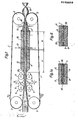
- Fig.l is shown schematically the arrangement and its operation.
- the arrangement consists of two endless bands 1 which are assumed here to be steel bands but which may also be other, preferably thermally conducting, bands or reinforced plastic bands.
- the steel bands 1 are passed over, and driven by, pulleys 2 which are arranged so that a synchronous movement is imparted to the steel bands 1.
- the parts of the steel bands 1 facing one another form a gap 19 and the size of this gap is determined by supporting or guiding surfaces 11 over which the steel bands 1 are conducted. It is intended to introduce into the gap 19 between the steel bands 1 a tube 3 of flexible material, e.g. plastic material, this tube being capable of being filled through a filling pipe 4 with a liquid product 6.
- the tube 3 which is received between the steel bands 1 in the gap 19 will be flattened as shown in fig.la, the product 6 advancing through a gaplike space which is formed in the flattened tube 3.
- the said gaplike space has a flow area which is substantially smaller than the flow area of the non- flattened tube, which means that the contents 6 which advance through the tube 3 in the parts where the cross-sectional area is reduced will be at a higher speed in relation to the tube than in other parts of the tube 3.
- the contents 6 which are introduced through the filling pipe 4 into the tube have, as shown, a speed v0, which in principle corresponds to the rate of feed of the tube 3 if the level of contents in the tube is to be kept constant.
- the speed v of the contents in the flattened tube is considerably greater and may go up to approx. 10 times the speed V o .
- the arrangement is also provided with a pumping device 5 which in the case shown here is a peristaltic pump, that is to say a pump which by means of periodical contractions forces the pumped object to advance through a duct.
- the pumping device 5 consists of two pairs of driven rollers 9 over which a guide chain or guide way 8 is arranged.
- On the said guide chain or guide way 8 are provided pressure roller 7.
- the driving rollers 9 of the pump operate synchronously with one another so that the pressure rollers 7 engage in pairs with one another and between themselves pick up the steel bands 1 together with the parts of the tube 3 present between the steel bands.
- the compression rollers 7 are controlled so that they compress the steel bands 1 with great force against one another which means that the tube 3 will be closed tightly in the compression region 10.
- the guide chains 8 are driven along at a speed V l which is considerably greater than the speed V 2 of the steel bands (approx. 5 - 20 times greater), which means that the rollers will roll along the steel bands 1, with the region of compression 10 being displaced along the steel bands 1 in the direction of advance of the steel bands.
- the pumping device 5 is designed so that any two compression rollers 7 which engage with one another do not release contact with one another before the rollers 7 coming next in the pumping cycle have fully engaged with one another. Hence the pumping arrangement 5 functions so that at least one pair of rollers 7 is always in engagement with one another.
- the liquid product 6 is pumped forward, therefore, in the direction of feed of the tube into a pressure zone 20 where the pressure is approx. 2.7 - 3 atmospheres above atmospheric pressure.
- the pressure is achieved partly with the help of the pump and partly with the help of supporting elements 11 of the steel bands with the help of which the gap 19 between the steel bands 1, and consequently the compression of the tube 4 is controlled.
- the flattened tube 3 filled with pressurized product 6 is now introduced into a heating zone V, where heat is supplied to such an extent that the product is heated to approx. 140 0 C which owing to the pressure having been raised can take place without the product coming to the boil. Moreover, the packing material is heated to such an extent that its inside becomes sterile.
- heat is supplied by providing magnetic induction coils 12 in the supporting elements 11 of the steel bands 1. With the help of the said magnetic induction coils eddy currents are induced in the zone of the steel bands 1 which lies next to the induction coils, with the result that the steel bands 1 are heated and by means of conduction and convection transfer heat to the tube 3 located between the steel bands 1 and hence also to the product 6.
- the product 6 which as supplied through the filling pipe 4 had a temperature of approx. 80 C is heated successively in the heating zone V to 140PC at which temperature the product is to be held for approx. 4-6 seconds. Subsequently the product must be rapidly cooled, however, so that it does not acquire an unpleasant, boiled taste and this takes place in the cooling zone K.
- the supporting elements 11 are provided in the contact surface between the supporting elements and the steel bands 1 with channels 35 through which can flow cooling liquid.
- This cooling liquid may for example be water which is pumped through the said channels 35, cooling on the one hand the steel bands 1 whilst on the other hand the heat absorbed can be used for the preheating of the product 6 intended for sterilization, in a manner which will be described later.
- the product 6 inside the tube 3 continues to be under a pressure of approx. 3 atmospheres above atmospheric pressure and this pressure has to be relieved before the support can be removed from the steel bands 1.
- This pressure relief is achieved in the throttling zone 16, in which zone the gap between the steel bands 1 is reduced further in that the supporting elements 11 are brought together more closely either in such a manner that a parallel gap is obtained which is substantially smaller than the gap 19 between the steel bands which exists in the heating and cooling zone or else in such a manner that the distance between the steel bands diminishes successively towards the driving pulleys 2 of the steel bands.
- the liquid resistance in the gap is made use of for reducing the pressure in the tube 3 to normal atmospheric pressure.
- the size and shape of the gap in the throttling zone varies depending on the viscosity of the product 6 treated. For this reason the supporting elements 11 in the throttling zone 16 should be adjustable so that the gap can be adapted to allow the desired pressure reduction to be obtained.
- the tube 3 which loses the support between the steel bands 1 will expand and the relative speed between the product and the tube once more will become insignificant owing to the increase in the cross-sectional area of the tube.
- the said tube 3 filled with liquid 6 can be divided in a known manner into packing containers by means of repeated transverse seals in regions perpendicularly to the tube 3, whereupon the sealed and divided packages can be separated to individual packing units with the help of cuts through the said sealing regions 17.
- fixed or movable side supports 18 if required may be provided between the outer edges of the steel bands 1 so as to support the side edges of the flattened tube 3 too if the pressure on these parts of the tube happens to be excessive.
- the tube 3 ought to be able to absorb these forces against the parts of the side walls exposed between the steel bands 1 without outer support because the gap between the steel bands is very small, but as mentioned fixed supporting walls 18 may be provided if necessary between the steel bands 1 within the zones where the interior of the tube 3 is under pressure, or else an endless, narrow belt which is driven at the same speed as the steel bands 1 may be arranged between them on either side of the steel bands so that friction between the tube 3 and the supports 18 is avoided.
- Fig.l is not true to scale but that in a typical case the tube 3 is compressed so much that the gap between the steel bands 1 becomes approx. 4 mm or less.
- the diameter of the tube 3 of circular cross-section may in practice be approx. 10-20 cm and the thickness of the steel bands approx. O.5 mm.
- the said peristaltic pump 5 can be in the form as described schematically above and as will be described in greater detail in the following, but it is also possible to arrange the pump 5 in such a manner that only one "chain” 8 with pressure rollers 7 is made to rotate and that these press the steel bands 1 against a fixed, hard base. It is also possible to arrange two pressure rollers 7 on movable arms, one of the rollers together with its arm being made to roll over a certain distance along the steel bands 1 and thereby displace the compression zone 10, whilst the other pressure roller 7 is moved against the direction of the bands to a starting position where the roller 7 is pressed against the bands 1.
- the principle is the same, namely that one roller or a pair of rollers shall always be in engagement with the bands 1 and that the tube 3 shall always be compressed so as to pinch off the pressure zone 20 from the inlet end of the tube 3.
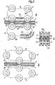
- band c is shown a pump 5 of the type as shown in Fig.l, namely a pump consisting of a guide chain or carrier chain 8 which carries rotating pressure rollers 7 which are supported on axle spindles carried by the chain 8.
- the rollers 7 are pressed against one another either through the driving chain 8 being controlled by a compression plate 21 or through the axle spindles of the rollers running in control grooves 22, which are indicated in Fig.2a.
- the pump is shown in another pumping cycle with only one pair of rollers 7 engaged with one another.
- the movement of the steel bands 1 in vertical direction is controlled with the help of fixed supporting elements 11 which in the pumping zone are constituted of rails 24, these rai_ 5 being located in the manner as shown in Fig.2c in recesses 23 in the rollers 7.
- the rails 24 thus function as supports of the bands 1 and limit the movement of the said bands in vertical direction when the pressure in the tube 3 varies in rhythm with the working cycles of the pump 5.
- the contraction zones or compression zones 10 will move along the bands 1 and thereby advance the product 6 which is present in the tube 3 towards the pressure zone 20.
- the rollers 7 have to roll forward at a higher speed than the bands 1 and the tube 3 which are advanced at a synchronous speed. In reality the rolling speed of the rollers 7 is approx. 5 - 20 times greater than the speed of advance of the bands 1 (a typical value is 10 times the band speed).
- the pumping problem may be solved in another manner different from that indicated here, but it has been found that the solution with two chains 8 with co-operating pressure rollers 7 is to be preferred over a chain where the pressure rollers 7 work against a hard base, since the limited flexibility of the steel bands 1 brings with it that a smaller quantity of contents can be pumped forward if only the one steel band 1 can bulge out to give space for the product and this design, furthermore, has the inconvenience that sliding between steel bands 1 occurs, since the bulged out part of the steel band 1 will be somewhat longer than the part of the opposite steel band 1 which rests against a plane base.
- a pump 5 of the type which is shown in Fig.2 gives a pulsating pumping which produces undesirable pressure variations in the system.
- This can be remedied through the introduction of a so-called equalizing device 27 which in principle consists in that the supports 11 for the steel bands 1 over a certain limited distance are resilient so as to allow a widening of the steel bands 1 and hence a widening of the tube 3 when a pressure surge occurs.
- the tube 3 can thus be widened temporarily and acquire locally a larger volume which means that the pressure can be rapidly levelled out and that after passing the equalizing device 27 the pressure in the product 6 by and large will be constant and independent of the pressure surges which are generated by the pumping device 5.
- Fig. is shown an embodiment which consists in widening the supporting plates 11 within a region and providing in the said region pressure plates 25 which are spring-loaded by means of springs 26.
- the pressure plates 25 are resilient and rest directly against the bands 1.
- This increasing pressure has the effect that in the region of the resilient supporting plates 25 these plates will spring backwards and locally provide a larger space for the product 6 in the tube 3 so that the pressure is quickly levelled out.
- the underside of the latter can be provided with rolls placed tightly next to each other.
- springs 26 it is also possible to make the supporting arrangement 11 resilient in the region of the equalizing device 27.
- the tube 3 should have an opportunity to expand locally and provide a larger space for the product 6 within the widened zone so as to neutralize any pressure surges from the pumping device 5.
- the tube passes into the heating zone 50 and the cooling zone for heat treatment which will be described later.
- these zones there is a pressure of approx. 3 atmospheres above atmospheric pressure in order to prevent the product from being brought to boiling point during the heating.
- This pressure has to be reduced to atmospheric pressure or near atmospheric pressure before the support of the tube 3 by the steel bands 1 can end.
- the reduction of the pressure in the tube 3 is achieved with the help of the liquid resistance which is produced when the product in the tube is conducted through a throttling zone 16.
- Fig.4 is shown how such a throttling zone 16 can be arranged.
- the steel bands 1 are supported and guided by supporting elements 11 and at the conclusion of the pressure zone 20 the steel bands 1 are led towards one another so that the gap between the steel bands 1 is further diminished.
- the tube 3 is further squeezed together so that the area of flow for the product 6 is appreciably diminished.
- the diminution of the gap between the steel bands 1 occurs in a transition zone 34 where the walls of the supporting elements 11 lead the steel bands towards one another until the gap between the steel bands 1 has diminished appreciably to required size (e.g. from a gap in the pressure zone of 4 mm to a gap in the throttling zone of 0.5 - 0.6 mm).
- roller mat 28 of the type as shown in Fig.4.
- the rollers in the roller mats 28 can be adjustable so that the gap between the steel bands is controllable and this can also be achieved by means of a throttling governor 29 consisting of a pair of rollers 30 which via arms are manoeuvrable by pneumatic or hydraulic manoeuvring pistons 31.
- the throttling governor 29 may also be constituted, in a manner known in itself, of a regulating screw which is turned by hand when the throttling and consequently the pressure require adjustment.. Since the liquid resistance in the throttling zone varies for products with different degrees of viscosity, it is necessary to be able to adjust the gap in the throttling zone so that the pressure in the pressure zone is wholly compensated when the tube 3 ceases to be supported by the steel bands. When the support of the tube 3 by the steel bands ends a widened part of tube 33 is formed which has such a large area of flow that the difference in speed between the contents 6 and the advancing tube 3 disapgears.
- the widened part of tube 33 containing the product is subsequently converted in the manner described earlier to individual packages through repeated transverse sealing of the tube 3 with the help of known packing machines, e.g. those where sealing jaws are provided on controlled chains and the sealing jaws are made to engage in pairs with the tube which is flattened and sealed whilst being compressed between the sealing jaws. Since the sa:id transport chain carries sealing jaws at a certain distance from one another, repeated seals of the tube at equal intervals are obtained. In order that each packing unit should contain the same volume of liquid, however, the driving speed of the chains which carry the sealing jaws must be adapted so that they operate synchronously with the amounts of product 6 and tube 3 fed through.
- the amount of tube 3 that is fed is always constant since the steel bands 1 and hence also the tube 3 are advanced at a constant rate, whilst in contrast the amount of product varies somewhat depending on how much product is dispensed to the tube 3. This in turn depends on the pressure in the throttling zone 16 and for this reason a controller 32 is provided which monitors the widening of the tube 3 in the throttling zone 16 to make it possible to control the speed of the chain on the packing machine 62 which carries the sealing jaws, and as a result obtain packages with a constant volume.
- a governor is acted on by the monitoring device 32 with the result that rising pressure on the monitoring device 32 will cause the speed of the steel bands 1 and of the packing machine 62 to increase whilst diminishing pressure will bring about a decrease in the speed of the steel bands 1 and of the packing machine 62. In this way a constant flow of the product 6 is achieved and the speed of travel of the steel bands 1 to suit this flow is regulated.
- FIG.6 A cross-section through the heating zone 50 is shown in Fig.6 and a cross-section through the heating, holding and cooling zones 52,59,58 is shown in Fig.7.
- the supporting elements 11 are provided with open channels1 5 these channels communicating with each other within each zone and being arranged in loops along the steel bands 1.
- the said ducts or channels 35 are connected, in a manner which will be described later, to a pipeline system for the supply of cooling water and drawing off of the cooling water after it has been heated.
- the steel bands 1 are in direct contact with the opening of the channels 35 and it is ensured that the contact surface of the supporting elements 11 with the steel bands 1 is so uniform that a substantially water-tight contact is obtained. To achieve further tightening the steel bands 1 are pressed against the sliding surface of the supporting elements 11 under pressure.
- induction coils 12 are inserted in the heating zone 50 in order to permit heating of the steel bands within the heating zone. These induction coils are fed in known manner (not shown here) by means of a high-frequency generator, and with the help of the coils eddy currents are induced in the steel bands 1. These eddy currents generate heat in the material and this heat is subsequently transferred by convection to the tube 3 and the product 6.
- edge zones 36 of the tube 3 are not supported by any pressure-absorbing arrangement. As mentioned earlier, this does not generally produce any major problem, since the forces in these edge zones are not great, as the gap 19 between the steel bands 1 is only small.
- the material in the tube 3 if it is a plastic material, will be weakened through heating which means that it is easily extended and deformed.
- it is necessary to support the edge zones which can be done in the manner mentioned earlier by means of outer supporting devices 18 which are introduced between the edge zones of the steel bands, and which are preferably driven synchronously at the same speed as the bands 1 and the tube 3 so as to prevent friction between the tube edge and the supporting surface 18.
- outer supporting devices 18 which are introduced between the edge zones of the steel bands, and which are preferably driven synchronously at the same speed as the bands 1 and the tube 3 so as to prevent friction between the tube edge and the supporting surface 18.
- the bands 1 it is further necessary to adapt the bands 1 to the material which is present in the tube 3 and it may be suitable in certain cases to provide the steel bands 1 with a coating of teflon or similar material in order to prevent "sticking" between the warm plastic tube 3 and the steel bands 1 when the plastic tube is heated to temperatures which substantially exceed the softening temperature of the plastics.
- the principle of the arrangement thus lies in supporting the tube 3 and the packing material in the tube 3 within the zones which owing to the heat have inferior strength characteristics so as to prevent deformation or bursts in the tube 3 at the same time as the pressure in these zones has to be high enough to prevent steam formation in the product 6.
- Fig. 5 is shown schematically an arrangement in accordance with the invention where the different parts described earlier have been assembled to a unit and where moreover the cooling and heat exchange system can be explained more fully in its principle.
- a packing material is rolled off a magazine roll, not shown, in the form of a web 37.
- the web 37 consists of plastic film of e.g. polyethylene, polypropylene, polyester or some other suitable plastic material or some laminate comprising a number of different materials.
- the packing material web 37 may also consist in certain cases of a material with a base layer of paper or cardboard which may contain e.g. an aluminium foil layer as one of the laminate layers.
- the packing material web 37 is conducted over a deflection roller vertically or obliquely downwards with simultaneous formation of the web 37 to a tube 3 by combining edge zones of the web 37 with one another in a joint, the edge zones being sealed with the help of a longitudinal joint sealing device 40 of conventional type.
- the contents 6 are introduced into the tube 3 formed through the filling pipe 4 and the supply of the contents 6 is regulated by means of a level controller 39 of optional type.
- the tube 3 is guided successively by means of guide rails or guide pulleys 41 in between the two steel bands 1 described earlier, these steel bands 1 being supported from the inside by means of supporting elements 11 so that an accurately defined gap 19 between the steel bands 1 is obtained.
- this gap is usually approx. 4 mm, but it may vary depending on packing material, contents, rate of production required etc.
- the :ube 3 When the :ube 3 has been introduced between the steel bands 1 it will be flattened down to become almost flat so that the area of flow for the contents 6 consists only of a narrow, elongated passage. This means, as mentioned earlier, that the area of flow for the contents 6 in the tube 3 is substantially diminishec.
- the plastic tube 3 is supported in all parts by the steel bands 1 which thus have a treble function, namely to support the tube 3, to transfer and to absorb heat from the tube 3 and the product 6 and to transport the tube through the treatment arrangement.
- the product 6 has to be pumped into the pressure zone 20 and this is carried out with the help of a peristaltic pump 5 as described earlier.
- the tube 3 At least up to and including the pressurizing of the tube 3, the tube 3 must be actively compressed by the steel bands 1 which in turn must be supported by supporting elements 11 which act upon the back of the bands during the whole time whilst the tube 3 is under pressure. This may give rise to friction problems, since the bands 1 are pressed against the supporting elements 11 owing to the internal pressure in the tube 3 and the bands 1 in their movement slide against.the supporting elements 11, the contact surface within the pressure zone being essential.
- the channels 35 are required to conduct cooling liquid which is in contact with the steel bands 1 and absorbs heat from the same, but this cooling liquid may also be used for eliminating or at least reducing the friction problem in respect of the sliding of the bands 1 along the sliding surface of the supporting elements 11. If it is assumed that the internal pressure in the tube 3 is approx. 3 atmospheres above atmospheric pressure the bands 1 will be pressed against the supporting elements 11 with a substantial force because the contact surface is so large. On the other hand, if the liquid pressure in the cooling channels goes up to a value just below the pressure in the tube 3, (e.g. 2.7 atmospheres above atmospheric pressure), the pressure under which the bands 1 are pressed against the sliding surfaces of the supporting elements 11 will be only the differential pressure between the pressure in the tube 3 and the pressure in the liquid channels 35.
- the area within which the tube 3 is under pressure can be divided into a number of zones, namely a preheating zone 52, a heating zone 50, a holding zone 59 and a cooling zone 58. These zones, with the exception of the holding zone 59 and the cooling zone 58, are separated from each other in such a manner that the cooling channels 35 in the different zones are included in separate, closed flow systems.
- induction coils 12 are provided in the supporting elements 11 in the heating zone 50, these induction coils 12 inducing eddy currents in the bands 1 in the manner as described previously.
- the said eddy currents induce heat in the bands 1, this heat being transferred subsequently by conduction and convection to the tube 3 and the product 6.
- the tube 3 has passed through a preheating zone 52 where hot water in the channels 35 is made to heat the product which at the start had a temperature of 20 °C.
- the temperature is raised to approx. approx. 80 C to a temperature of approx./140°C, this temperature to be maintained for approx.
- the cooling water of a temperature of approx. 10°C is introduced through a supply line 44 whereupon the pressure of the cooling water is raised with the help of a pump 45 to a pressure which lies just below the pressure in the tube 3.
- the pressure of the pump 45 can be regulated with the help of a governor which monitors the pressure in the tube 3 and controls the pump 45 as a function of the monitored result.
- From the pump 45 the cold cooling water is conducted through a pressure duct 46 into a system of cooling water channels 35 which are arranged within the holding zone 59 and the cooling zone 58 mentioned earlier.
- the cold cooling water is introduced into the part of the cooling zone 58 which is located foremost in the direction of advance of the tube 3.
- the cooling water which flows under pressure in the channels 35 reduces on the one hand the pressure between the bands 1 and the supporting elements 11 and absorbs on the other hand heat from the bands 1 and hence from the tube 3 and the product 6 so that the product at the exit from the pressure zone has a temperature of approx. 20°C.
- the cooling water flows through the channels 35 with simultaneous absorption of heat and at the start of the cooling zone 58 the continuing product has a temperature of approx. 140 C which means that the so-called holding zone 59 follows on.
- the cooling water continues to flow through the channels 35 with simultaneous absorption of heat and is drawn off through the duct 56 to a main heat exchanger 43 where the heated cooling water is forced to heat a cold product 6 coming from storage.
- the cold product (approx.
- the water within the circulation system in the heating zone 50 is conducted therefore through the channels 35 which are provided in the supporting elements 11 in the heating zone 50 and is then conducted through pipeline 63 into a secondary heat exchanger 48 where heat is discharged to the cooling water which passes through the shunt line 47 to the secondary heat exchanger 48.
- the cooling water heated on its passage through the secondary heat exchanger 48 is then conducted through the pipeline 55 back to the supply duct 56 for the main heat exchanger 43.
- the heating zone 52 too has a separate circulation system of channels 35 in the supporting elements 11 and here, as is evident from the name of the treatment zone, it is not a question of some cooling, but of preheating of the product 6.
- This preheating is achieved in that a part of the cooling water, which has passed through the cooling zone 58 and has been heated in the process, is drawn off through a shunt line 57 and is pumped by means of the pump 51 through the channel system 35 into the preheating zone 52.
- the product 6 and the tube 3 are heated in this zone to approx. 120°C.
- the water which has discharged a part of its heat content in the preheating zone 52 is drawn off through pipeline 53 to supply line 56 and hence to the main heat exchanger 43 where the remaining heat content in the water is used for preheating the product 6.
- the cooled and pressure-reduced tube 3 leaves the bands 1 and is conducted out to atmospheric pressure without support by the bands 1, which means that the tube 3 endeavours to assume a substantially circular cross-sectional area with increasing area of flow and corresponding diminution in the relative speed between the product 6 and the tube 3.
- the tube 3 is now introduced into any kind of packing machine 62 of known type, e.g. one which has sealing jaws arranged on a rotating chain and where the sealing jaws are pressed against one another from opposite sides of the tube with simultaneous compression and heating of the tube, so that the plastic material is caused to melt to form a tight and durable sealing join.
- the tube 3 can thus be pressed flat and sealed at equal intervals to form cushion-shaped packages, or else a shaping of the material of the package may be carried out in association with the sealing operation so that the package acquires a lasting geometric shape or else the bags formed are inserted into containers of cardboard or the like which are manufactured separately.
- the packing material consists of plastic film or plastic film laminate, but it is conceivable that fibrous material such as e.g. paper or aluminium foil may also be included in the laminate. If aluminium foil is included in the laminate it is conceivable that the steel bands might be substituted by rigid bands of some other material, e.g. reinforced plastic bands and that the bands would then have only a supporting, and not any heat- transmitting function. In this case the heat required for the heat treatment can be generated directly in the aluminium foil layer of the packing laminate with the help of the said induction coils 12 which are provided in the supporting elements 11. It will be more difficult, of course, to provide an effective cooling if the bands 1 do not have sufficient thermal conductivity, but in certain cases, e.g. when the heat treatment does not have to be carried on as far as sterilization, that is to say heating to 14o C, it is conceivable to use reinforced plastic bands instead of steel bands as supporting devices.
- reinforced plastic bands instead of steel bands as supporting devices.
- the arrangement may also be used for so-called pasteurization, which has been mentioned in the beginning, and in this case the arrangement will be considerably simpler, since a pasteurization implies only heating of the product 6 up to approx. 90°C.
- a pasteurization implies only heating of the product 6 up to approx. 90°C.
- Such heating means therefore, that a pressure zone 20 does not have to be installed, so that the pumping device 5, the equalizing device 27 and the throttling zone 16 in certain cases can be elminated.
- the circulation system in the cooling arrangement will be considerably simpler and can be reduced to a channel system and a heat exchanger.
- a tube 3 is manufactured in the manner as described earlier and filled with contents 6.
- the tube 3 is then pressed flat as it is introduced between two bands 1 supported by the supporting elements 11.
- a flow duct of a substantially reduced surface is obtained in the tube 3 and the said fast flow of product through the flattened tube 3 will take place.
- the product can be heated in the manner as shown through heat transfer from the bands 1 or through the generation of heat in a layer of aluminium foil in the packing material, whereupon the tube 3 with its contents, after the support by the bands 1 has ended can be packaged in a packing machine 62 of known type.
- a pump for the pressure relief of the product can be, for example, a peristaltic pump of the same design as pump 5.
Abstract
Description
- The present invention relates to a method for the continuous heat treatment and packaging of a liquid product, in particular with the object of reducing the content of micro-organisms of the product, the product being heated for a short time together with, and surrounded by, the packing material wherein it is to be enclosed and subsequently cooled again. The invention also relates to an arrangement for the carrying out of the method.
- It frequently happens in the technique of packaging that products which are to be packaged are subjected to a heat treatment before the actual packaging, mostly in order to reduce the content of bacteria and other micro-organisms of the product. It is of course primarily foodstuffs which are subjected to such a heat treatment, the ultimate object of the heat treatment being in general the prolongation of the keeping quality of the product. If the heat treatment is carried out long enough to prevent all bacterial growth, it is said in general that the product has been sterilized, which means that it can be kept in its package for a very long time (a number of months) without the product turning sour or being impaired in some other manner through microbiological effects. It is a pre-condition, however, if the product is to remain durable in its package that the packaging of the product has to be carried out under aseptic conditions and that the parts of the packing material which come into contact with the sterilized contents are aseptic.
- It is known that milk, fruit juices, water etc. can be sterilized by means of heat treatment and subsequent packaging of the sterilized product under aseptic conditions into previously sterilized packing material, whereupon the packed product can be kept in its unopened package for a very long time. This packing process, in principle, is divided into two stages, namely
- a) heat treatment of the product with the object of reducing the content of micro-organisms, and
- b) packaging of the product comprising treatment of the packing material in order to sterilize the surfaces which come into contact with the product.
- The heat treatment of the product which for example may be milk, can be carried out in any known apparatus, e.g. a plate apparatus which in principle is a heat exchanger where the heat-emitting medium flows along one path of flow and the milk intended for heat treatment along an opposite path of flow, the two flow media being separated by thin metal walls which readily transfer thermal energy from the heat-emitting medium to the heat-absorbing medium. Such "plate apparatuses" are used mainly for the so-called pasteurizing of milk, that is to say heating to approx. 90 C in order to neutralize pathogenic bacteria. If a complete sterilization of the milk is to be carried out, a more comprehensive heat treatment and a heating to 1460C for a few seconds is required. Such a heating, as a rule, is not carried out in so-called plate apparatuses, but in other types of heating arrangements where usually a jet or a film of milk is made to encounter a flow of superheated steam, the milk being heated rapidly to sterilization temperature. The heat-treated milk can be collected in sterilized tanks or containers awaiting packaging.
- For the actual packaging the sterilized milk is conducted under aseptic conditions to a packing machine wherein a web or a blank of packing material is sterilized internally before the sterilized milk is introduced. This filling and closing process must take place in a sterile room so as to hinder the sterilized milk or the sterilized packing material from being infected by bacteria present in the air.
- The most customary and most rational method is to start off with a packing material web with a plastic-coated inside, this packing material web, possibly after treatment with liquid sterilizing agent, e.g. hydrogen peroxide, being formed to a tube in that longitudinal edges of the web are combined with one another in a tight join, whereupon the contents are introduced into the internally sterilized tube which by means of repeated transverse seals, perpendicularly to the tube axis, is divided to form individual package units which can be separated by cutting through the said seal-ng zones. In certain cases the sterilizing effect of the packing material is intensified by allowing the tube of packing material formed to pass a source of heat which by means of radiant heat or in some other manner heats the plastic inside of the tube to such an extent that any micro-organisms present on the packing material web are rendered harmless at the same time as any residues of sterilizing agent are evaporated.
- Another method for the manufacture of aseptic packages consists in first making blanks which with the help of automatic machines can be raised to boxes provided with a base. These boxes can subsequently be sterilized on the inside in that hydrogen peroxide is introduced into the packing box in vapour form or in the form of small liquid particles, whereupon hot air or steam is blown into the packing box, on the one hand to enhance the sterilizing effect and on the other hand to eliminate the hydrogen peroxide. The package thus sterilized on the inside is then filled with sterilized product and closed in a sterile chamber.
- Both these known methods for packaging sterilized products, e.g. sterilized milk, are used commercially, but it has proved a major difficulty and factor of uncertainty that the sterilization of the product and the sterilization of the packing material have to be carried out in two separate stages and product and package have to be combined thereafter. The uncertainty lies, among other things, in that the product has to pass a number of valves and pipelines of different types where a risk of infection is always present in pipe joints, valve seals etc.
- It would be an advantage, therefore, if the heat treatment could be carried out in one stage in which the product and the packing material would be jointly sterilized and the product enclosed in the packing material. Such a process is known in itself, e.g. from Swedish patent specification no. 7307105-2 which describes an apparatus wherein a product, e.g. milk, is introduced into a p'astic tube, this plastic tube being conducted through a heating zone, e.g. heated liquid, and is cooled down again thereafter. During the treatment in the hot bath the tube is compressed between rollers so that it is given a reduced area of flow which means that the liquid which is fed to the tube within the region which has a reduced area of flow will be at a higher speed in relation to the tube. This means that the liquid is given a shorter residence time in the heating zone than the tube of packing material, but owing to the tube being flattened the column of liquid which runs through the tube will be very narrow so that all parts of the liquid come into good thermal contact with the heated walls of the tube. After the heating and cooling the tube is widened again so that the cross-sectional area increases and the relative speed between liquid and tube diminishes. At the actual packing, the speeds of the liquid and of the tube will be the same.
- Such a known arrangement has the disadvantage, however, that it is difficult to carry on the heat treatment so long that the liquid which passes through the tube is heated to a temperature which exceeds its boiling point. A boiling of the liquid brings about a formation of steam which renders the process impossible and which besides prevents further heating. It is necessary therefore that the treatment should be done under pressure so that the liquid can be heated to approx. 14opc without boiling. To this end a pressure of approx. 2.6 - 3 atmospheres above atmospheric pressure is required, that is to say a pressure which the actual tube cannot withstand if the tube material consists of a thin plastic film, especially if the tube is heated to a temperature which exceeds the softening point of most plastic materials.
- This technical problem has been solved, however, in accordance with the invention by a method which is characterized in that the product is introduced into a tube of flexible material, whereupon the said tube containing the product is introduced between two substantially parallel bands movable synchronously in their longitudinal direction, preferably of heat-conducting material, that the tube is received and compressed between the bands so that the tube is transported with the bands at the same time as the cross-sectional area of the tube is reduced and the product is made to flow forward through the compressed tube in a gaplike space of substantially uniform gap width, that heat is generated in or is transferred to a zone of the said movable bands which through conduction and convection transfer the thermal energy required for the said treatment to the tube and the product contained in the tube, that the tube and the product, after the heat treatment has been carried during the necessary period, are cooled through thermal energy being given off to or through another zone of the said bands.
- An embodiment of the invention will be described in the following with reference to the attached schematic drawing wherein,
- Fig.l shows a schematic picture of the arrangement in accordance with the invention,
- Fig.2 shows a pumping device,
- Fig.3 shows an equalizing device,
- Fig.4 shows a throttling device for the equalization of the pressure,
- Fig.5 shows an assembly of the arrangement as a whole,
- Fig.6 show a cross-section through the supporting and guiding surfaces for the control of the steel bands.
- For the sake of clarity the same reference designations are used in the following for the different parts, even if they occur in different figures.
- In Fig.l is shown schematically the arrangement and its operation.
- As can be seen from Fig.l the arrangement consists of two endless bands 1 which are assumed here to be steel bands but which may also be other, preferably thermally conducting, bands or reinforced plastic bands. The steel bands 1 are passed over, and driven by, pulleys 2 which are arranged so that a synchronous movement is imparted to the steel bands 1. The parts of the steel bands 1 facing one another form a
gap 19 and the size of this gap is determined by supporting or guidingsurfaces 11 over which the steel bands 1 are conducted. It is intended to introduce into thegap 19 between the steel bands 1 atube 3 of flexible material, e.g. plastic material, this tube being capable of being filled through a filling pipe 4 with aliquid product 6. Thetube 3 which is received between the steel bands 1 in thegap 19 will be flattened as shown in fig.la, theproduct 6 advancing through a gaplike space which is formed in theflattened tube 3. The said gaplike space has a flow area which is substantially smaller than the flow area of the non- flattened tube, which means that thecontents 6 which advance through thetube 3 in the parts where the cross-sectional area is reduced will be at a higher speed in relation to the tube than in other parts of thetube 3. - The
contents 6 which are introduced through the filling pipe 4 into the tube have, as shown, a speed v0, which in principle corresponds to the rate of feed of thetube 3 if the level of contents in the tube is to be kept constant. The speed v of the contents in the flattened tube, however, is considerably greater and may go up to approx. 10 times the speed Vo. - The arrangement is also provided with a pumping device 5 which in the case shown here is a peristaltic pump, that is to say a pump which by means of periodical contractions forces the pumped object to advance through a duct. In the case described here the pumping device 5 consists of two pairs of driven rollers 9 over which a guide chain or guide way 8 is arranged. On the said guide chain or guide way 8 are provided
pressure roller 7. The driving rollers 9 of the pump operate synchronously with one another so that thepressure rollers 7 engage in pairs with one another and between themselves pick up the steel bands 1 together with the parts of thetube 3 present between the steel bands. Thecompression rollers 7 are controlled so that they compress the steel bands 1 with great force against one another which means that thetube 3 will be closed tightly in thecompression region 10. The guide chains 8 are driven along at a speed Vl which is considerably greater than the speed V2 of the steel bands (approx. 5 - 20 times greater), which means that the rollers will roll along the steel bands 1, with the region ofcompression 10 being displaced along the steel bands 1 in the direction of advance of the steel bands. The pumping device 5 is designed so that any twocompression rollers 7 which engage with one another do not release contact with one another before therollers 7 coming next in the pumping cycle have fully engaged with one another. Hence the pumping arrangement 5 functions so that at least one pair ofrollers 7 is always in engagement with one another. - With the help of the pumping device 5 the
liquid product 6 is pumped forward, therefore, in the direction of feed of the tube into apressure zone 20 where the pressure is approx. 2.7 - 3 atmospheres above atmospheric pressure. The pressure is achieved partly with the help of the pump and partly with the help of supportingelements 11 of the steel bands with the help of which thegap 19 between the steel bands 1, and consequently the compression of the tube 4 is controlled. - The
flattened tube 3 filled withpressurized product 6 is now introduced into a heating zone V, where heat is supplied to such an extent that the product is heated to approx. 1400C which owing to the pressure having been raised can take place without the product coming to the boil. Moreover, the packing material is heated to such an extent that its inside becomes sterile. In the example given here heat is supplied by providing magnetic induction coils 12 in the supportingelements 11 of the steel bands 1. With the help of the said magnetic induction coils eddy currents are induced in the zone of the steel bands 1 which lies next to the induction coils, with the result that the steel bands 1 are heated and by means of conduction and convection transfer heat to thetube 3 located between the steel bands 1 and hence also to theproduct 6. - The
product 6 which as supplied through the filling pipe 4 had a temperature of approx. 80 C is heated successively in the heating zone V to 140PC at which temperature the product is to be held for approx. 4-6 seconds. Subsequently the product must be rapidly cooled, however, so that it does not acquire an unpleasant, boiled taste and this takes place in the cooling zone K. In the said cooling zone K the supportingelements 11 are provided in the contact surface between the supporting elements and the steel bands 1 withchannels 35 through which can flow cooling liquid. This cooling liquid may for example be water which is pumped through the saidchannels 35, cooling on the one hand the steel bands 1 whilst on the other hand the heat absorbed can be used for the preheating of theproduct 6 intended for sterilization, in a manner which will be described later. When the cooling medium cools the steel bands 1 the temperature of the steel bands will drop, the thermal energy will be transferred from theproduct 6 to the steel bands 1, so that the temperature of theproduct 6 rapidly drops and that at the end of the cooling zone it has a temperature of approx. 20 C. - However, the
product 6 inside thetube 3 continues to be under a pressure of approx. 3 atmospheres above atmospheric pressure and this pressure has to be relieved before the support can be removed from the steel bands 1. This pressure relief is achieved in the throttlingzone 16, in which zone the gap between the steel bands 1 is reduced further in that the supportingelements 11 are brought together more closely either in such a manner that a parallel gap is obtained which is substantially smaller than thegap 19 between the steel bands which exists in the heating and cooling zone or else in such a manner that the distance between the steel bands diminishes successively towards the driving pulleys 2 of the steel bands. Thus the liquid resistance in the gap is made use of for reducing the pressure in thetube 3 to normal atmospheric pressure. The size and shape of the gap in the throttling zone varies depending on the viscosity of theproduct 6 treated. For this reason the supportingelements 11 in the throttlingzone 16 should be adjustable so that the gap can be adapted to allow the desired pressure reduction to be obtained. - The
tube 3 which loses the support between the steel bands 1 will expand and the relative speed between the product and the tube once more will become insignificant owing to the increase in the cross-sectional area of the tube. The saidtube 3 filled withliquid 6 can be divided in a known manner into packing containers by means of repeated transverse seals in regions perpendicularly to thetube 3, whereupon the sealed and divided packages can be separated to individual packing units with the help of cuts through the said sealing regions 17. - As is evident from Fig.la fixed or movable side supports 18 if required may be provided between the outer edges of the steel bands 1 so as to support the side edges of the flattened
tube 3 too if the pressure on these parts of the tube happens to be excessive. In general thetube 3 ought to be able to absorb these forces against the parts of the side walls exposed between the steel bands 1 without outer support because the gap between the steel bands is very small, but as mentioned fixed supportingwalls 18 may be provided if necessary between the steel bands 1 within the zones where the interior of thetube 3 is under pressure, or else an endless, narrow belt which is driven at the same speed as the steel bands 1 may be arranged between them on either side of the steel bands so that friction between thetube 3 and thesupports 18 is avoided. - It should be pointed out that Fig.l is not true to scale but that in a typical case the
tube 3 is compressed so much that the gap between the steel bands 1 becomes approx. 4 mm or less. The diameter of thetube 3 of circular cross-section may in practice be approx. 10-20 cm and the thickness of the steel bands approx. O.5 mm. - The schematic arrangement which is shown in Fig.l may in practice certainly be designed in many different ways and in the following a possible design of an operating arrangement will be described in more detail.
- The said peristaltic pump 5 can be in the form as described schematically above and as will be described in greater detail in the following, but it is also possible to arrange the pump 5 in such a manner that only one "chain" 8 with
pressure rollers 7 is made to rotate and that these press the steel bands 1 against a fixed, hard base. It is also possible to arrange twopressure rollers 7 on movable arms, one of the rollers together with its arm being made to roll over a certain distance along the steel bands 1 and thereby displace thecompression zone 10, whilst theother pressure roller 7 is moved against the direction of the bands to a starting position where theroller 7 is pressed against the bands 1. The principle is the same, namely that one roller or a pair of rollers shall always be in engagement with the bands 1 and that thetube 3 shall always be compressed so as to pinch off thepressure zone 20 from the inlet end of thetube 3. - In Fig.2a,band c is shown a pump 5 of the type as shown in Fig.l, namely a pump consisting of a guide chain or carrier chain 8 which carries
rotating pressure rollers 7 which are supported on axle spindles carried by the chain 8. Therollers 7 are pressed against one another either through the driving chain 8 being controlled by acompression plate 21 or through the axle spindles of the rollers running incontrol grooves 22, which are indicated in Fig.2a. In Fig.2b the pump is shown in another pumping cycle with only one pair ofrollers 7 engaged with one another. The movement of the steel bands 1 in vertical direction is controlled with the help of fixed supportingelements 11 which in the pumping zone are constituted ofrails 24, these rai_5 being located in the manner as shown in Fig.2c inrecesses 23 in therollers 7. Therails 24 thus function as supports of the bands 1 and limit the movement of the said bands in vertical direction when the pressure in thetube 3 varies in rhythm with the working cycles of the pump 5. As mentioned earlier, the contraction zones orcompression zones 10 will move along the bands 1 and thereby advance theproduct 6 which is present in thetube 3 towards thepressure zone 20. This means that therollers 7 have to roll forward at a higher speed than the bands 1 and thetube 3 which are advanced at a synchronous speed. In reality the rolling speed of therollers 7 is approx. 5 - 20 times greater than the speed of advance of the bands 1 (a typical value is 10 times the band speed). - As mentioned earlier, the pumping problem may be solved in another manner different from that indicated here, but it has been found that the solution with two chains 8 with
co-operating pressure rollers 7 is to be preferred over a chain where thepressure rollers 7 work against a hard base, since the limited flexibility of the steel bands 1 brings with it that a smaller quantity of contents can be pumped forward if only the one steel band 1 can bulge out to give space for the product and this design, furthermore, has the inconvenience that sliding between steel bands 1 occurs, since the bulged out part of the steel band 1 will be somewhat longer than the part of the opposite steel band 1 which rests against a plane base. - A pump 5 of the type which is shown in Fig.2 gives a pulsating pumping which produces undesirable pressure variations in the system. This can be remedied through the introduction of a so-called
equalizing device 27 which in principle consists in that thesupports 11 for the steel bands 1 over a certain limited distance are resilient so as to allow a widening of the steel bands 1 and hence a widening of thetube 3 when a pressure surge occurs. In the equalizingdevice 27 thetube 3 can thus be widened temporarily and acquire locally a larger volume which means that the pressure can be rapidly levelled out and that after passing the equalizingdevice 27 the pressure in theproduct 6 by and large will be constant and independent of the pressure surges which are generated by the pumping device 5. - Purely practically the equalizing
device 27 can be designed in many different ways. In Fig. is shown an embodiment which consists in widening the supportingplates 11 within a region and providing in the saidregion pressure plates 25 which are spring-loaded by means of springs 26. Thepressure plates 25 are resilient and rest directly against the bands 1. When a pressure surge occurs the pressure in thetube 3 is increased and hence the pressure between thetube 3 and the steel bands 1 and also between the steel bands 1 and the supporting surfaces 11. This increasing pressure has the effect that in the region of the resilient supportingplates 25 these plates will spring backwards and locally provide a larger space for theproduct 6 in thetube 3 so that the pressure is quickly levelled out. - To achieve a reduction in the friction between the steel bands 1 and the supporting
plates 25 the underside of the latter can be provided with rolls placed tightly next to each other. Instead of using springs 26 it is also possible to make the supportingarrangement 11 resilient in the region of the equalizingdevice 27. The main thing is that thetube 3 should have an opportunity to expand locally and provide a larger space for theproduct 6 within the widened zone so as to neutralize any pressure surges from the pumping device 5. - From the equalizing
device 27 the tube passes into the heating zone 50 and the cooling zone for heat treatment which will be described later. In these zones, as mentioned, there is a pressure of approx. 3 atmospheres above atmospheric pressure in order to prevent the product from being brought to boiling point during the heating. This pressure has to be reduced to atmospheric pressure or near atmospheric pressure before the support of thetube 3 by the steel bands 1 can end. In the present case it is assumed that the reduction of the pressure in thetube 3 is achieved with the help of the liquid resistance which is produced when the product in the tube is conducted through a throttlingzone 16. In Fig.4 is shown how such athrottling zone 16 can be arranged. As is evident from Fig.4 the steel bands 1 are supported and guided by supportingelements 11 and at the conclusion of thepressure zone 20 the steel bands 1 are led towards one another so that the gap between the steel bands 1 is further diminished. This means also that thetube 3 is further squeezed together so that the area of flow for theproduct 6 is appreciably diminished. Since the steel bands 1 cannot be bent over a narrow bending radius, the diminution of the gap between the steel bands 1 occurs in atransition zone 34 where the walls of the supportingelements 11 lead the steel bands towards one another until the gap between the steel bands 1 has diminished appreciably to required size (e.g. from a gap in the pressure zone of 4 mm to a gap in the throttling zone of 0.5 - 0.6 mm). Because of the liquid resistance the pressure in thetube 3 decreases successively, but since some pressure remains the steel bands 1 must continue to be supported in almost the whole throttling zone which can be done by means of an extension of the supportingelements 11 or by introducing aroller mat 28 of the type as shown in Fig.4. The rollers in theroller mats 28 can be adjustable so that the gap between the steel bands is controllable and this can also be achieved by means of a throttling governor 29 consisting of a pair ofrollers 30 which via arms are manoeuvrable by pneumatic orhydraulic manoeuvring pistons 31. The throttling governor 29 may also be constituted, in a manner known in itself, of a regulating screw which is turned by hand when the throttling and consequently the pressure require adjustment.. Since the liquid resistance in the throttling zone varies for products with different degrees of viscosity, it is necessary to be able to adjust the gap in the throttling zone so that the pressure in the pressure zone is wholly compensated when thetube 3 ceases to be supported by the steel bands. When the support of thetube 3 by the steel bands ends a widened part oftube 33 is formed which has such a large area of flow that the difference in speed between thecontents 6 and the advancingtube 3 disapgears. The widened part oftube 33 containing the product is subsequently converted in the manner described earlier to individual packages through repeated transverse sealing of thetube 3 with the help of known packing machines, e.g. those where sealing jaws are provided on controlled chains and the sealing jaws are made to engage in pairs with the tube which is flattened and sealed whilst being compressed between the sealing jaws. Since the sa:id transport chain carries sealing jaws at a certain distance from one another, repeated seals of the tube at equal intervals are obtained. In order that each packing unit should contain the same volume of liquid, however, the driving speed of the chains which carry the sealing jaws must be adapted so that they operate synchronously with the amounts ofproduct 6 andtube 3 fed through. The amount oftube 3 that is fed is always constant since the steel bands 1 and hence also thetube 3 are advanced at a constant rate, whilst in contrast the amount of product varies somewhat depending on how much product is dispensed to thetube 3. This in turn depends on the pressure in the throttlingzone 16 and for this reason acontroller 32 is provided which monitors the widening of thetube 3 in the throttlingzone 16 to make it possible to control the speed of the chain on the packingmachine 62 which carries the sealing jaws, and as a result obtain packages with a constant volume. - It is also possible with the help of the control in the throttling
zone 16 to regulate the pressure in thepressure zone 20, that is to say, should the pressure in the pressure zone be too low, which would imply a risk that the product might boil, further throttling can take place in the throttlingzone 16 so that the pressure in thepressure zone 20 increases and vice versa. The accuracy of volume of the package produced is determined by the bag or package filling a fixed cavity in the packing machine. If the speed of the steel bands and of the chain on the packingmachine 62 is too low the pressure in thetube 3 before the packingmachine 62 will increase and this increase in pressure is monitored by themonitoring device 32. A governor is acted on by themonitoring device 32 with the result that rising pressure on themonitoring device 32 will cause the speed of the steel bands 1 and of the packingmachine 62 to increase whilst diminishing pressure will bring about a decrease in the speed of the steel bands 1 and of the packingmachine 62. In this way a constant flow of theproduct 6 is achieved and the speed of travel of the steel bands 1 to suit this flow is regulated. - A cross-section through the heating zone 50 is shown in Fig.6 and a cross-section through the heating, holding and cooling zones 52,59,58 is shown in Fig.7.
- As is evident from Fig. 6 the supporting
elements 11 are provided with open channels15these channels communicating with each other within each zone and being arranged in loops along the steel bands 1. The said ducts orchannels 35 are connected, in a manner which will be described later, to a pipeline system for the supply of cooling water and drawing off of the cooling water after it has been heated. The steel bands 1 are in direct contact with the opening of thechannels 35 and it is ensured that the contact surface of the supportingelements 11 with the steel bands 1 is so uniform that a substantially water-tight contact is obtained. To achieve further tightening the steel bands 1 are pressed against the sliding surface of the supportingelements 11 under pressure. This pressure must not be too great, though, since otherwise the friction forces become so great that it becomes difficult to move the steel bands 1 along whilst they are in contact with the supportingelements 11. The steel bands 1 are pressed against the supportingelements 11 owing to a pressure of approx. 3 atmospheres above atmospheric pressure prevailing in thepressure zone 20 which owing to the relatively great length and width of the pressure zone provides appreciable contact forces. These contact forces are neutralized, however, because the cooling water which is introduced into thechannels 35 has a pressure which is only a few tenths of an atmosphere less than the pressure in thepressure zone 20 of thetube 3, which means that it is only the difference between the pressure in thepressure zone 20 and the pressure in thecooling water channels 35 which is effective between the steel bands 1 and the sliding surfaces of the supportingelements 11. This pressure must always be positive, though, so that a sealing of thechannels 35 is obtained, since otherwise the cooling medium (water in the present case) would squirt out between the steel bands 1 and the supportingelements 11. In.the supportingelements 11induction coils 12 are inserted in the heating zone 50 in order to permit heating of the steel bands within the heating zone. These induction coils are fed in known manner (not shown here) by means of a high-frequency generator, and with the help of the coils eddy currents are induced in the steel bands 1. These eddy currents generate heat in the material and this heat is subsequently transferred by convection to thetube 3 and theproduct 6. - As is evident e edge zones 36 of the
tube 3 are not supported by any pressure-absorbing arrangement. As mentioned earlier, this does not generally produce any major problem, since the forces in these edge zones are not great, as thegap 19 between the steel bands 1 is only small. However, it has to be borne in mind that the material in thetube 3, if it is a plastic material, will be weakened through heating which means that it is easily extended and deformed. In these cases it is necessary to support the edge zones, which can be done in the manner mentioned earlier by means of outer supportingdevices 18 which are introduced between the edge zones of the steel bands, and which are preferably driven synchronously at the same speed as the bands 1 and thetube 3 so as to prevent friction between the tube edge and the supportingsurface 18. Another manner of solving this problem is shown in Fig. 6 where the supportingelements 11 have a concave contact surface against the steel bands 1 which means that thesupportinj elements 11 successively force the edge zones of the steel bands towards one another, or at least bring them so near to one another, that the width of the edge zones of thetube 3 is substantially reduced. By closing the pressure zone space for thetube 3 in this manner, the latter will be supported in all its parts, thus preventing any deformation of the tube material even if it is heated to softening. In this manner the problem of thetube 3, if made of plastic film of losing important parts of its mechanical properties is eliminated. - It is further necessary to adapt the bands 1 to the material which is present in the
tube 3 and it may be suitable in certain cases to provide the steel bands 1 with a coating of teflon or similar material in order to prevent "sticking" between the warmplastic tube 3 and the steel bands 1 when the plastic tube is heated to temperatures which substantially exceed the softening temperature of the plastics. - It is not necessary of course to supply heat electrically with the help of induction coils. It is also possible to supply heat to the bands 1 by means of a heated liquid medium which is conducted in the said
channels 35 within the heating zone 50. These channels in the heating zone will then form a separate channel system. In general it is difficult, however, to reach a sufficient temperature in this manner, so that the main importance of heating by means of liquid heating medium rests perhaps in heat treatment not aiming at full sterility but being limited to lower temperature, e.g. pasteurization. The principle of the arrangement thus lies in supporting thetube 3 and the packing material in thetube 3 within the zones which owing to the heat have inferior strength characteristics so as to prevent deformation or bursts in thetube 3 at the same time as the pressure in these zones has to be high enough to prevent steam formation in theproduct 6. - In Fig. 5 is shown schematically an arrangement in accordance with the invention where the different parts described earlier have been assembled to a unit and where moreover the cooling and heat exchange system can be explained more fully in its principle.
- As is evident from Fig.5 a packing material is rolled off a magazine roll, not shown, in the form of a web 37. In the present case it is assumed that the web 37 consists of plastic film of e.g. polyethylene, polypropylene, polyester or some other suitable plastic material or some laminate comprising a number of different materials. As will be described later, the packing material web 37 may also consist in certain cases of a material with a base layer of paper or cardboard which may contain e.g. an aluminium foil layer as one of the laminate layers.
- The packing material web 37 is conducted over a deflection roller vertically or obliquely downwards with simultaneous formation of the web 37 to a
tube 3 by combining edge zones of the web 37 with one another in a joint, the edge zones being sealed with the help of a longitudinaljoint sealing device 40 of conventional type. Thecontents 6 are introduced into thetube 3 formed through the filling pipe 4 and the supply of thecontents 6 is regulated by means of alevel controller 39 of optional type. Thus it is the intention to attempt holding the level of contents at a relatively constant height which is below the longitudinal joint seal but nevertheless so high that a sufficient static pressure is obtained for the filling and stretching out of thetube 3. Thetube 3 is guided successively by means of guide rails or guide pulleys 41 in between the two steel bands 1 described earlier, these steel bands 1 being supported from the inside by means of supportingelements 11 so that an accurately definedgap 19 between the steel bands 1 is obtained. As mentioned earlier, this gap is usually approx. 4 mm, but it may vary depending on packing material, contents, rate of production required etc. When the :ube 3 has been introduced between the steel bands 1 it will be flattened down to become almost flat so that the area of flow for thecontents 6 consists only of a narrow, elongated passage. This means, as mentioned earlier, that the area of flow for thecontents 6 in thetube 3 is substantially diminishec. Consequently the contents or theproduct 6 which in the filling region did not have any flow movement of significance in relation to the tube 3 (constant product level), will now flow through the tube at a speed which is substantially greater than the rate of feed of thetube 3. In the case where the heat treatment aims at sterilization, i.e. where the product is to be heated to approx. 140°C (milk) and held at that temperature for approx. 4 seconds, theproduct 6 has to be put under pressure so as not to be brought to the boil. The heat treatment itself thus has to be carried out in apressure zone 20 where the internal pressure in thetube 3 is substantial (approx. 3 atmospheres above atmospheric pressure), a pressure which thetube 3 cannot withstand, especially when the packing material is heated to a temperature of approx. 140°C, that is to say a temperature which substantially exceeds the softening temperature of most plastic materials. In the case described here, however, theplastic tube 3 is supported in all parts by the steel bands 1 which thus have a treble function, namely to support thetube 3, to transfer and to absorb heat from thetube 3 and theproduct 6 and to transport the tube through the treatment arrangement. - In order to attain the desired pressure the
product 6 has to be pumped into thepressure zone 20 and this is carried out with the help of a peristaltic pump 5 as described earlier. At least up to and including the pressurizing of thetube 3, thetube 3 must be actively compressed by the steel bands 1 which in turn must be supported by supportingelements 11 which act upon the back of the bands during the whole time whilst thetube 3 is under pressure. This may give rise to friction problems, since the bands 1 are pressed against the supportingelements 11 owing to the internal pressure in thetube 3 and the bands 1 in their movement slide against.the supportingelements 11, the contact surface within the pressure zone being essential. - This problem is solved in that e.g. certain parts of the supporting
elements 11 are constituted of rollers,e.g. roller mats 28 in the throttling zone 16 (though it should be possible in most cases to substitute the roller mats by sliding surfaces, since the internal pressure in thetube 3 successively diminishes within the throttling zone 16). Within substantial parts of the zones where thetube 3 is under pressure and the steel bands 1 are thus pressed agains t the sliding surfaces on the supportingelements 11, the problem can be solved with the help of theliquid channels 35 which areprovided in the supportingelements 11. Thechannels 35 are required to conduct cooling liquid which is in contact with the steel bands 1 and absorbs heat from the same, but this cooling liquid may also be used for eliminating or at least reducing the friction problem in respect of the sliding of the bands 1 along the sliding surface of the supportingelements 11. If it is assumed that the internal pressure in thetube 3 is approx. 3 atmospheres above atmospheric pressure the bands 1 will be pressed against the supportingelements 11 with a substantial force because the contact surface is so large. On the other hand, if the liquid pressure in the cooling channels goes up to a value just below the pressure in thetube 3, (e.g. 2.7 atmospheres above atmospheric pressure), the pressure under which the bands 1 are pressed against the sliding surfaces of the supportingelements 11 will be only the differential pressure between the pressure in thetube 3 and the pressure in theliquid channels 35. This means a substantial reduction in the force with which the bands 1 are pressed against the supporting elements and a corresponding reduction in the friction forces which have to be overcome when the bands 1 are made to slide over the sliding surfaces of the supportingelements 11. A certain pressure between the bands 1 and the sliding surfaces of the supportingelements 11 has to be maintained however, since otherwise liquid from theliquid channels 35 would leak out between the supportingelements 11 and the bands 1 which would not be desirable. - When the internal pressure in the
tube 3 has risen owing to theproduct 6 being pumped into thepressure zone 20 with the help of thepressure rollers 7 of the pumping device, pressure surges will occur, as mentioned earlier, since the pumping device 5 produces a pulsating pumping sequence. These pressure surges are eliminated in the manner as described earlier by means of apressure equalizing device 27 consisting of a resilient, expandable chamber which increases its volume as a pressure surge occurs and as a result the pressure in thetube 3, after passage of theproduct 6 through the equalizingdevice 27, will be substantially constant. - The area within which the
tube 3 is under pressure can be divided into a number of zones, namely a preheating zone 52, a heating zone 50, a holding zone 59 and a cooling zone 58. These zones, with the exception of the holding zone 59 and the cooling zone 58, are separated from each other in such a manner that the coolingchannels 35 in the different zones are included in separate, closed flow systems. - As is evident from Fig.5 , induction coils 12 are provided in the supporting
elements 11 in the heating zone 50, theseinduction coils 12 inducing eddy currents in the bands 1 in the manner as described previously. The said eddy currents induce heat in the bands 1, this heat being transferred subsequently by conduction and convection to thetube 3 and theproduct 6. Before the heating zone, however, thetube 3 has passed through a preheating zone 52 where hot water in thechannels 35 is made to heat the product which at the start had a temperature of 20 °C. In the heat zone 50 the temperature is raised to approx. approx. 80 C to a temperature of approx./140°C, this temperature to be maintained for approx. 4 seconds, which means that the temperature of 140°C is maintained also after the tube has left the heating zone 50 and has entered into the cooling zone where the temperature of theproduct 6 and thetube 3 is lowered successively to approx. 20°C. Then the pressure is reduced in the throttlingzone 16, in the manner described earlier, to atmospheric pressure. This heat control of thetube 3 and of theproduct 6 which flows through thetube 3 within thepressure zone 20 at a substantially greater speed than the rate of feed of thetube 3 is achieved with the help of a cooling water circulation system which will now be described in greater detail. - The cooling water of a temperature of approx. 10°C is introduced through a supply line 44 whereupon the pressure of the cooling water is raised with the help of a
pump 45 to a pressure which lies just below the pressure in thetube 3. The pressure of thepump 45 can be regulated with the help of a governor which monitors the pressure in thetube 3 and controls thepump 45 as a function of the monitored result. From thepump 45 the cold cooling water is conducted through apressure duct 46 into a system of coolingwater channels 35 which are arranged within the holding zone 59 and the cooling zone 58 mentioned earlier. The cold cooling water is introduced into the part of the cooling zone 58 which is located foremost in the direction of advance of thetube 3. The cooling water which flows under pressure in thechannels 35 reduces on the one hand the pressure between the bands 1 and the supportingelements 11 and absorbs on the other hand heat from the bands 1 and hence from thetube 3 and theproduct 6 so that the product at the exit from the pressure zone has a temperature of approx. 20°C. The cooling water flows through thechannels 35 with simultaneous absorption of heat and at the start of the cooling zone 58 the continuing product has a temperature of approx. 140 C which means that the so-called holding zone 59 follows on. The cooling water continues to flow through thechannels 35 with simultaneous absorption of heat and is drawn off through theduct 56 to amain heat exchanger 43 where the heated cooling water is forced to heat acold product 6 coming from storage. The cold product (approx. 200C)is conducted to the saidheat exchanger 43 through apipeline 60 and in theheat exchanger 43 takes up thermal energy from the outgoing cooling water so that at the outlet from theheat exchanger 43 the product has a temperature of approx. 80°C. The product which has been preheated is conducted through the filling pipe 4 into thetube 3 formed. - Not all the cooling water which is supplied through the pipeline 44 is conducted through the
pump 45 and the cooling zone 58, but a part of the cooling water is drawn off through theshunt line 47 and is passed to asecondary heat exchanger 48 whose function consists in absorbing heat from water and cooling the same within a closed system ofcirculation 63 which is not a cooling system in itself but is used for balancing out the pressure between the bands 1 and the supportingelements 11 so that the friction resistance between the bands and the supporting elements within the heating zone 50 is reduced. This closed circulation system thus incorporates thecirculation channels 35 within the heating zone 50, and since the water in this zone is brought to boiling point if it is not allowed to give off heat the saidseparate circulation system 63 has been provided, where the water is circulated with the help of aseparate pump 49. The water within the circulation system in the heating zone 50 is conducted therefore through thechannels 35 which are provided in the supportingelements 11 in the heating zone 50 and is then conducted throughpipeline 63 into asecondary heat exchanger 48 where heat is discharged to the cooling water which passes through theshunt line 47 to thesecondary heat exchanger 48. The cooling water heated on its passage through thesecondary heat exchanger 48 is then conducted through thepipeline 55 back to thesupply duct 56 for themain heat exchanger 43. - The heating zone 52 too has a separate circulation system of
channels 35 in the supportingelements 11 and here, as is evident from the name of the treatment zone, it is not a question of some cooling, but of preheating of theproduct 6. This preheating is achieved in that a part of the cooling water, which has passed through the cooling zone 58 and has been heated in the process, is drawn off through ashunt line 57 and is pumped by means of thepump 51 through thechannel system 35 into the preheating zone 52. Theproduct 6 and thetube 3 are heated in this zone to approx. 120°C. The water which has discharged a part of its heat content in the preheating zone 52 is drawn off throughpipeline 53 to supplyline 56 and hence to themain heat exchanger 43 where the remaining heat content in the water is used for preheating theproduct 6. - After the pressure reduction in the throttling
zone 16, which has been described earlier, the cooled and pressure-reducedtube 3 leaves the bands 1 and is conducted out to atmospheric pressure without support by the bands 1, which means that thetube 3 endeavours to assume a substantially circular cross-sectional area with increasing area of flow and corresponding diminution in the relative speed between theproduct 6 and thetube 3. Thetube 3 is now introduced into any kind of packingmachine 62 of known type, e.g. one which has sealing jaws arranged on a rotating chain and where the sealing jaws are pressed against one another from opposite sides of the tube with simultaneous compression and heating of the tube, so that the plastic material is caused to melt to form a tight and durable sealing join. As the sealing devices on the said chains are arranged at a fixed distance from each other, thetube 3 can thus be pressed flat and sealed at equal intervals to form cushion-shaped packages, or else a shaping of the material of the package may be carried out in association with the sealing operation so that the package acquires a lasting geometric shape or else the bags formed are inserted into containers of cardboard or the like which are manufactured separately. - It has been described earlier how it is possible by regulating the speed of the driven bands 1, the pump 5 or the chain on the packing
machine 62 to ensure that the packing containers have a constant and desired volume. - In the present case it has been assumed that the packing material consists of plastic film or plastic film laminate, but it is conceivable that fibrous material such as e.g. paper or aluminium foil may also be included in the laminate. If aluminium foil is included in the laminate it is conceivable that the steel bands might be substituted by rigid bands of some other material, e.g. reinforced plastic bands and that the bands would then have only a supporting, and not any heat- transmitting function. In this case the heat required for the heat treatment can be generated directly in the aluminium foil layer of the packing laminate with the help of the said induction coils 12 which are provided in the supporting
elements 11. It will be more difficult, of course, to provide an effective cooling if the bands 1 do not have sufficient thermal conductivity, but in certain cases, e.g. when the heat treatment does not have to be carried on as far as sterilization, that is to say heating to 14o C, it is conceivable to use reinforced plastic bands instead of steel bands as supporting devices. - In principle the arrangement may also be used for so-called pasteurization, which has been mentioned in the beginning, and in this case the arrangement will be considerably simpler, since a pasteurization implies only heating of the
product 6 up to approx. 90°C. Such heating means, therefore, that apressure zone 20 does not have to be installed, so that the pumping device 5, the equalizingdevice 27 and the throttlingzone 16 in certain cases can be elminated. It may be necessary, though, to use a pump, even in pasteurizing devices, for conducting theproduct 6 through the system. Moreover, the circulation system in the cooling arrangement will be considerably simpler and can be reduced to a channel system and a heat exchanger. When an arrangement in accordance with the invention is to be used for the pasteurizing of milk in connection with packaging of the latter, atube 3 is manufactured in the manner as described earlier and filled withcontents 6. Thetube 3 is then pressed flat as it is introduced between two bands 1 supported by the supportingelements 11. As thetube 3 is flattened a flow duct of a substantially reduced surface is obtained in thetube 3 and the said fast flow of product through the flattenedtube 3 will take place. The product can be heated in the manner as shown through heat transfer from the bands 1 or through the generation of heat in a layer of aluminium foil in the packing material, whereupon thetube 3 with its contents, after the support by the bands 1 has ended can be packaged in a packingmachine 62 of known type. - In the embodiment of the invention described here it is assumed that the pressure relief of the product is carried out with the help of a throttling zone, with the liquid resistance in the said throttling zone used for pressure relief. It may be advantageous in certain cases and for certain products to use instead of the said throttling zone a pump for the pressure relief of the product. Such a pump can be, for example, a peristaltic pump of the same design as pump 5.
- It is also possible to generate the heat required for heat treatment direction in the product and the heating can then be done with the help of microwaves using known microwave generators.
- Substantial advantages can thus be gained by using an arrangement in accordance with the invention which by no means is restricted to the embodiments here described, but which comprises any embodiments where the
tube 3 filled with liquid is introduced between, and is supported by, wide bands 1 which on the one hand control the cross-sectional area of thetube 3 and support its walls and on the other hand supply and/or absorb heat from the tube and theproduct 6 introduced into the tube.
Claims (20)
Priority Applications (1)
| Application Number | Priority Date | Filing Date | Title |
|---|---|---|---|
| AT85100996T ATE33964T1 (en) | 1984-02-16 | 1985-01-31 | PROCESS AND DEVICE FOR THE CONTINUOUS HEAT TREATMENT AND PACKAGING OF THE LIQUID PRODUCT. |
Applications Claiming Priority (2)
| Application Number | Priority Date | Filing Date | Title |
|---|---|---|---|
| SE8400827 | 1984-02-16 | ||
| SE8400827A SE451829C (en) | 1984-02-16 | 1984-02-16 | SET AND DEVICE FOR CONTINUOUS HEAT TREATMENT AND PACKAGING OF SCIENTIFIC PRODUCT |
Publications (3)
| Publication Number | Publication Date |
|---|---|
| EP0152018A2 true EP0152018A2 (en) | 1985-08-21 |
| EP0152018A3 EP0152018A3 (en) | 1985-09-25 |
| EP0152018B1 EP0152018B1 (en) | 1988-05-04 |
Family
ID=20354766
Family Applications (1)
| Application Number | Title | Priority Date | Filing Date |
|---|---|---|---|
| EP85100996A Expired EP0152018B1 (en) | 1984-02-16 | 1985-01-31 | A method and an arrangement for the continuous heat treatment and packaging of a liquid product |
Country Status (6)
| Country | Link |
|---|---|
| US (2) | US4731250A (en) |
| EP (1) | EP0152018B1 (en) |
| JP (1) | JPH0764343B2 (en) |
| AT (1) | ATE33964T1 (en) |
| DE (1) | DE3562470D1 (en) |
| SE (1) | SE451829C (en) |
Families Citing this family (27)
| Publication number | Priority date | Publication date | Assignee | Title |
|---|---|---|---|---|
| AT393771B (en) * | 1985-12-23 | 1991-12-10 | Heden Team Ag | Apparatus and process for the automatic production of foods and foodstuffs in piece form from dough-like substances |
| SE8802218D0 (en) * | 1988-06-14 | 1988-06-14 | Alfastar Ab | PLANT FOR HEAT TREATMENT OF A LIQUID WHILE FLOWING THROUGH A FLEXIBLE PIPE TRANSFERRED IN THE FLOW DIRECTION |
| SE8802217D0 (en) * | 1988-06-14 | 1988-06-14 | Alfastar Ab | PLANT FOR TREATING A LIQUID THAT FLOWS THROUGH A TUBE OF FLEXIBLE MATERIAL |
| JPH0825549B2 (en) * | 1989-01-13 | 1996-03-13 | 株式会社小松製作所 | Packaging system for continuous strip packaging |
| US5440860A (en) * | 1989-06-05 | 1995-08-15 | Schreiber Foods, Inc. | Method and apparatus for forming and hermetically sealing slices of food items |
| DE19501106A1 (en) * | 1995-01-17 | 1996-07-18 | Natec Reich Summer Gmbh Co Kg | Method and device for shaping and portioning a viscous mass |
| US5697291A (en) * | 1995-05-15 | 1997-12-16 | Questron Inc. | Method and apparatus for microwave enhanced pasteurization and enzyme inactivation of continuously flowing product |
| SE511029C2 (en) * | 1995-07-03 | 1999-07-26 | Tetra Laval Holdings & Finance | Ways to achieve extended shelf life for a food |
| US5829224A (en) * | 1997-10-10 | 1998-11-03 | Tetra Laval Holdings & Finance, Sa | Method and apparatus for producing an aseptic heterogeneous food |
| JP3774053B2 (en) * | 1997-12-15 | 2006-05-10 | 藤森工業株式会社 | Bag contents sterilization apparatus and sterilization method |
| DE19801402A1 (en) | 1998-01-16 | 1999-07-22 | Natec Reich Summer Gmbh Co Kg | Method and device for shaping and portioning a soft, pasty product |
| DE69833480T2 (en) | 1998-10-07 | 2006-08-31 | Tetra Laval Holdings & Finance S.A. | Method and device for producing sealed packages of flowable foodstuffs from tubular packaging material |
| US6408644B1 (en) | 2000-08-21 | 2002-06-25 | Don Williams | Microwave home energy heating and cooling system |
| SE518499C2 (en) * | 2001-02-02 | 2002-10-15 | Tetra Laval Holdings & Finance | Apparatus for preparing a package or packaging material |
| US6843043B2 (en) * | 2002-09-13 | 2005-01-18 | Alkar Rapidpak, Inc. | Web packaging pasteurization system |
| US6976347B2 (en) * | 2002-09-13 | 2005-12-20 | Alkar-Rapidpak, Inc. | Surface pasteurization method |
| US7048825B2 (en) * | 2002-10-03 | 2006-05-23 | Weyerhaeuser Company | Microwave preheat press assembly |
| US20040265465A1 (en) * | 2003-06-30 | 2004-12-30 | Tropicana Products, Inc. | Cold de-aeration in production of citrus juices |
| US8088425B2 (en) * | 2003-10-08 | 2012-01-03 | Kraft Foods Global Brands Llc | Apparatus and method for surface treatment of a food product |
| US20080066430A1 (en) * | 2006-09-15 | 2008-03-20 | Triangle Package Machinery Company | Continuous motion drive mechanism for a form, fill, and seal machine |
| US7690174B2 (en) * | 2006-11-27 | 2010-04-06 | Kpc-Master's Craft International, Inc. | Compressing and conveying article through shrink packaging machine |
| US7976885B2 (en) * | 2007-10-23 | 2011-07-12 | Alkar-Rapidpak-Mp Equipment, Inc. | Anti-microbial injection for web packaging pasteurization system |
| US8539741B2 (en) * | 2010-02-10 | 2013-09-24 | Triangle Package Machinery Company | Seal and cut method and apparatus |
| CN106275645A (en) * | 2015-05-15 | 2017-01-04 | 可口可乐公司 | A kind of online molding, fill and encapsulate formed product packaging system and method |
| EP3341031A4 (en) | 2015-08-28 | 2019-03-06 | Papadopoulos, Michael | System and method for fluid sterilization |
| US10512701B2 (en) | 2015-08-28 | 2019-12-24 | Michael Papadopoulos | System for fluid sterilization for a vessel |
| US10358244B2 (en) | 2015-10-26 | 2019-07-23 | Triangle Package Machinery Co. | Rotatable sealing jaw assembly for a form, fill and seal machine |
Citations (1)
| Publication number | Priority date | Publication date | Assignee | Title |
|---|---|---|---|---|
| GB930651A (en) * | 1960-12-12 | 1963-07-10 | Alpura Ag | Apparatus for sterile packing of sterile substances |
Family Cites Families (12)
| Publication number | Priority date | Publication date | Assignee | Title |
|---|---|---|---|---|
| US1810864A (en) * | 1929-10-25 | 1931-06-16 | Vogt Instant Freezers Inc | Process for the production of food product bricks |
| US2070850A (en) * | 1935-11-15 | 1937-02-16 | Frank W Trabold | Meat product |
| US2550584A (en) * | 1949-02-03 | 1951-04-24 | Mittelmann Eugene | Milk pasteurization method and apparatus |
| US2613488A (en) * | 1950-08-18 | 1952-10-14 | George R Attride | Apparatus for packaging frozen fruit juices |
| US2816837A (en) * | 1952-07-21 | 1957-12-17 | Henry T Holsman | Packaging process and apparatus |
| US2759308A (en) * | 1953-10-05 | 1956-08-21 | Clearfield Cheese Company | Apparatus for producing individually wrapped cheese slabs |
| US3052559A (en) * | 1959-08-17 | 1962-09-04 | Foremost Dairies Inc | Sterilizing process |
| SE373022C (en) * | 1973-05-21 | 1976-12-16 | Alfa Laval Ab | APPARATUS FOR IMPLEMENTING AN ESSENTIAL UNIFORM TREATMENT OF A SUBSTANCE, SPEC EN VETSKA |
| US3961569A (en) * | 1974-08-15 | 1976-06-08 | The United States Of America As Represented By The Secretary Of The Army | Apparatus for continuous microwave sterilization of food in pouches |
| JPS534478A (en) * | 1976-07-02 | 1978-01-17 | Hitachi Ltd | Semiconductor device |
| US4265922A (en) * | 1979-01-31 | 1981-05-05 | General Mills, Inc. | Induction heating method for processing food material |
| US4642969A (en) * | 1985-03-27 | 1987-02-17 | Johnson Charles H | Method and apparatus for wrapping blocks of cheese |
-
1984
- 1984-02-16 SE SE8400827A patent/SE451829C/en not_active IP Right Cessation
-
1985
- 1985-01-31 DE DE8585100996T patent/DE3562470D1/en not_active Expired
- 1985-01-31 EP EP85100996A patent/EP0152018B1/en not_active Expired
- 1985-01-31 AT AT85100996T patent/ATE33964T1/en not_active IP Right Cessation
- 1985-02-16 JP JP60029181A patent/JPH0764343B2/en not_active Expired - Lifetime
-
1987
- 1987-04-17 US US07/039,761 patent/US4731250A/en not_active Expired - Fee Related
- 1987-05-29 US US07/055,320 patent/US4782643A/en not_active Expired - Lifetime
Patent Citations (1)
| Publication number | Priority date | Publication date | Assignee | Title |
|---|---|---|---|---|
| GB930651A (en) * | 1960-12-12 | 1963-07-10 | Alpura Ag | Apparatus for sterile packing of sterile substances |
Also Published As
| Publication number | Publication date |
|---|---|
| JPH0764343B2 (en) | 1995-07-12 |
| EP0152018B1 (en) | 1988-05-04 |
| SE8400827D0 (en) | 1984-02-16 |
| US4782643A (en) | 1988-11-08 |
| JPS60193859A (en) | 1985-10-02 |
| SE451829C (en) | 1992-10-28 |
| EP0152018A3 (en) | 1985-09-25 |
| ATE33964T1 (en) | 1988-05-15 |
| US4731250A (en) | 1988-03-15 |
| SE8400827L (en) | 1985-08-17 |
| SE451829B (en) | 1987-11-02 |
| DE3562470D1 (en) | 1988-06-09 |
Similar Documents
| Publication | Publication Date | Title |
|---|---|---|
| US4782643A (en) | Arrangement for the continuous heat treatment and packaging of a liquid product | |
| US5750966A (en) | Plant for pasteurizing or sterilising solid or liquid food products using microwaves | |
| USRE30780E (en) | Heat treatment of heat-sensitive products | |
| US4731980A (en) | Apparatus for forming a tube from polyfoil web for high capacity aseptic form, fill, and seal machines | |
| WO1983002050A1 (en) | Process and installation for applying a controllable heat-exchange in a regenerative heat-exchanger | |
| SE459083B (en) | DEVICE FOR GAS STERILIZATION OF A CURRENT PACKAGING MATERIAL RANGE | |
| AU2004200267B2 (en) | Surface pasteurization method | |
| US5546854A (en) | Apparatus for heating and sterilizing food | |
| US3913299A (en) | Apparatus for enveloping and treating substances | |
| US2748005A (en) | Method of canning foods | |
| US11780627B2 (en) | Method and filling machine for filling packages that are open on one side | |
| US4819414A (en) | Apparatus for forming a tube from polyfoil web for high capacity aseptic form, fill, and seal machines | |
| EP0588010A1 (en) | A method of preparing and packing liquid food with extended shelf life using high pressure | |
| CN206238303U (en) | A kind of pasteurization machine for ensureing food security | |
| EP4275708A1 (en) | Compact sterilization machine for the sterilization of caps | |
| EP3505456A1 (en) | A thermal treatment machine and a related method | |
| EP4091636B1 (en) | Sterilization machine for the sterilization of caps | |
| JPH0576328A (en) | High-pressure sterilization apparatus having temperature-control function | |
| CN209807004U (en) | Tunnel type sterilization machine | |
| CN106376120B (en) | Water circulation device for microwave heating | |
| CN212437175U (en) | Wide spraying sterilization machine of scope sprays gimbal mechanism | |
| Stoforos et al. | Thermal Processing Equipment for Heating and Cooling | |
| JP3029647B2 (en) | Sterilization filling device for fluids | |
| JPH01132360A (en) | Sterilization apparatus for canned food | |
| BR0206830B1 (en) | Food retention arrangement for heat treatment |
Legal Events
| Date | Code | Title | Description |
|---|---|---|---|
| PUAI | Public reference made under article 153(3) epc to a published international application that has entered the european phase |
Free format text: ORIGINAL CODE: 0009012 |
|
| PUAL | Search report despatched |
Free format text: ORIGINAL CODE: 0009013 |
|
| AK | Designated contracting states |
Designated state(s): AT BE CH DE FR GB IT LI LU NL |
|
| AK | Designated contracting states |
Designated state(s): AT BE CH DE FR GB IT LI LU NL |
|
| 17P | Request for examination filed |
Effective date: 19860123 |
|
| 17Q | First examination report despatched |
Effective date: 19860821 |
|
| RAP1 | Party data changed (applicant data changed or rights of an application transferred) |
Owner name: AB TETRA PAK |
|
| GRAA | (expected) grant |
Free format text: ORIGINAL CODE: 0009210 |
|
| AK | Designated contracting states |
Kind code of ref document: B1 Designated state(s): AT BE CH DE FR GB IT LI LU NL |
|
| REF | Corresponds to: |
Ref document number: 33964 Country of ref document: AT Date of ref document: 19880515 Kind code of ref document: T |
|
| ITF | It: translation for a ep patent filed |
Owner name: BARZANO' E ZANARDO MILANO S.P.A. |
|
| REF | Corresponds to: |
Ref document number: 3562470 Country of ref document: DE Date of ref document: 19880609 |
|
| ET | Fr: translation filed | ||
| PLBI | Opposition filed |
Free format text: ORIGINAL CODE: 0009260 |
|
| 26 | Opposition filed |
Opponent name: ALFASTAR AB Effective date: 19890124 |
|
| NLR1 | Nl: opposition has been filed with the epo |
Opponent name: ALFASTAR AB |
|
| RAP2 | Party data changed (patent owner data changed or rights of a patent transferred) |
Owner name: AB TETRA PAK |
|
| PLBM | Termination of opposition procedure: date of legal effect published |
Free format text: ORIGINAL CODE: 0009276 |
|
| STAA | Information on the status of an ep patent application or granted ep patent |
Free format text: STATUS: OPPOSITION PROCEDURE CLOSED |
|
| 27C | Opposition proceedings terminated |
Effective date: 19900722 |
|
| ITTA | It: last paid annual fee | ||
| EPTA | Lu: last paid annual fee | ||
| NLR2 | Nl: decision of opposition | ||
| PGFP | Annual fee paid to national office [announced via postgrant information from national office to epo] |
Ref country code: NL Payment date: 19971222 Year of fee payment: 14 Ref country code: AT Payment date: 19971222 Year of fee payment: 14 |
|
| PGFP | Annual fee paid to national office [announced via postgrant information from national office to epo] |
Ref country code: CH Payment date: 19980108 Year of fee payment: 14 |
|
| PGFP | Annual fee paid to national office [announced via postgrant information from national office to epo] |
Ref country code: LU Payment date: 19980109 Year of fee payment: 14 |
|
| PGFP | Annual fee paid to national office [announced via postgrant information from national office to epo] |
Ref country code: BE Payment date: 19980115 Year of fee payment: 14 |
|
| PG25 | Lapsed in a contracting state [announced via postgrant information from national office to epo] |
Ref country code: LU Free format text: LAPSE BECAUSE OF NON-PAYMENT OF DUE FEES Effective date: 19990131 Ref country code: LI Free format text: LAPSE BECAUSE OF NON-PAYMENT OF DUE FEES Effective date: 19990131 Ref country code: CH Free format text: LAPSE BECAUSE OF NON-PAYMENT OF DUE FEES Effective date: 19990131 Ref country code: BE Free format text: LAPSE BECAUSE OF NON-PAYMENT OF DUE FEES Effective date: 19990131 Ref country code: AT Free format text: LAPSE BECAUSE OF NON-PAYMENT OF DUE FEES Effective date: 19990131 |
|
| BERE | Be: lapsed |
Owner name: A.B. TETRA PAK Effective date: 19990131 |
|
| PG25 | Lapsed in a contracting state [announced via postgrant information from national office to epo] |
Ref country code: NL Free format text: LAPSE BECAUSE OF NON-PAYMENT OF DUE FEES Effective date: 19990801 |
|
| REG | Reference to a national code |
Ref country code: CH Ref legal event code: PL |
|
| PGFP | Annual fee paid to national office [announced via postgrant information from national office to epo] |
Ref country code: FR Payment date: 20010102 Year of fee payment: 17 |
|
| PGFP | Annual fee paid to national office [announced via postgrant information from national office to epo] |
Ref country code: DE Payment date: 20010103 Year of fee payment: 17 |
|
| PGFP | Annual fee paid to national office [announced via postgrant information from national office to epo] |
Ref country code: GB Payment date: 20010105 Year of fee payment: 17 |
|
| REG | Reference to a national code |
Ref country code: GB Ref legal event code: IF02 |
|
| PG25 | Lapsed in a contracting state [announced via postgrant information from national office to epo] |
Ref country code: GB Free format text: LAPSE BECAUSE OF NON-PAYMENT OF DUE FEES Effective date: 20020131 |
|
| PG25 | Lapsed in a contracting state [announced via postgrant information from national office to epo] |
Ref country code: DE Free format text: LAPSE BECAUSE OF NON-PAYMENT OF DUE FEES Effective date: 20020801 |
|
| GBPC | Gb: european patent ceased through non-payment of renewal fee |
Effective date: 20020131 |
|
| PG25 | Lapsed in a contracting state [announced via postgrant information from national office to epo] |
Ref country code: FR Free format text: LAPSE BECAUSE OF NON-PAYMENT OF DUE FEES Effective date: 20020930 |
|
| REG | Reference to a national code |
Ref country code: FR Ref legal event code: ST |