EP0151078B1 - High intensity mass spectrometer with simultaneous multiple detection - Google Patents
High intensity mass spectrometer with simultaneous multiple detection Download PDFInfo
- Publication number
- EP0151078B1 EP0151078B1 EP85400127A EP85400127A EP0151078B1 EP 0151078 B1 EP0151078 B1 EP 0151078B1 EP 85400127 A EP85400127 A EP 85400127A EP 85400127 A EP85400127 A EP 85400127A EP 0151078 B1 EP0151078 B1 EP 0151078B1
- Authority
- EP
- European Patent Office
- Prior art keywords
- sector
- electrostatic
- radial plane
- lens
- magnetic sector
- Prior art date
- Legal status (The legal status is an assumption and is not a legal conclusion. Google has not performed a legal analysis and makes no representation as to the accuracy of the status listed.)
- Expired
Links
Images


Classifications
-
- H—ELECTRICITY
- H01—ELECTRIC ELEMENTS
- H01J—ELECTRIC DISCHARGE TUBES OR DISCHARGE LAMPS
- H01J49/00—Particle spectrometers or separator tubes
- H01J49/26—Mass spectrometers or separator tubes
- H01J49/28—Static spectrometers
- H01J49/32—Static spectrometers using double focusing
- H01J49/326—Static spectrometers using double focusing with magnetic and electrostatic sectors of 90 degrees
-
- H—ELECTRICITY
- H01—ELECTRIC ELEMENTS
- H01J—ELECTRIC DISCHARGE TUBES OR DISCHARGE LAMPS
- H01J49/00—Particle spectrometers or separator tubes
- H01J49/26—Mass spectrometers or separator tubes
- H01J49/28—Static spectrometers
- H01J49/32—Static spectrometers using double focusing
- H01J49/322—Static spectrometers using double focusing with a magnetic sector of 90 degrees, e.g. Mattauch-Herzog type
Definitions
- the invention relates to a charged clarity particle separator or mass spectrometer for the identification and simultaneous measurement of several elements.
- the spectrometer is intended to receive a beam of charged particles or ions, composed by particles of different masses (M - M 1 , M 2 , Kt, etc.), animated by slightly different kinetic energies.
- M particles of different masses
- M 2 particles of different masses
- Kt etc.
- V eV
- a mass spectrometer generally has an entrance slit, after which the beam passes into an electrostatic sector, then into a magnetic sector.
- the purpose of this arrangement is to deflect the particles, in a selective manner as to their mass and as much as possible independently of their energy. The deviation occurs in a so-called radial plane which is the plane of symmetry of the instrument and which is perpendicular to the large dimension of the entry slit.
- the particle beam therefore has a radial component, and a perpendicular component, in what is called the vertical section.
- the quality of a mass spectrometer is defined by its separating power M / AM, where AM is the smallest difference in mass that can be distinguished with the instrument.
- AM the smallest difference in mass that can be distinguished with the instrument.
- this separating power would only depend on the dimensions of the entrance slit.
- the images of the entry slit, or lines are distorted by the optical defects of the device, called aberrations. These aberrations depend mainly on the energy dispersion AV of the ions, and on the beam opening which is limited by the opening slit which is inserted most of the time before the magnetic sector.
- the best spectrometer is the most sensitive, that is to say the one that accepts the beam with the greatest geometric extent. This ability is called “clarity" of the spectrometer.
- clarity can only be increased by reducing the harmful effect of aberrations.
- the problem is therefore to produce a mass spectrometer with high clarity, capable of simultaneous multiple detection and which has a high separating power.
- a first object of the present invention is to correct the proper aberrations of the spectrometer, in particular of its magnetic sector, and also of its electrostatic sector.
- a second object of the present invention is, using a transfer optic placed upstream of the mass spectrometer itself, to improve the adaptation and the transfer of the ion beam on the input of the spectrometer.
- the device proposed here comprises an inlet slot, followed by an electrostatic sector, then a magnetic sector.
- An opening slot can be inserted between the electrostatic and magnetic sectors or, in a conventional manner, at the entrance to the electrostatic sector.
- This assembly makes it possible to deflect a beam of particles in the radial plane perpendicular to the large dimension of the entry slit.
- the magnetic sector has a planar entry face, inclined on the axis of the particle beam, and an exit face also planar, the plane of which passes through the intersection of the entry face with the axis of the particle beam. This is the arrangement of the actual magnetic faces which differ from the material faces due to the leakage fields.
- the means recommended by this prior French patent consists of having a first lens electric (18) between the entrance slit (10) and the energy diaphragm (20) and a second electric lens (22) between the energy diaphragm (20) and the magnetic sector (24).
- the Patent specifies the role of these lenses, in relation to the aperture diaphragm and the adjustable energy diaphragm.
- the input face of the magnetic sector (24) is inclined by an angle e which happens to be equal to 26.6 °.
- This use of an inclined entry face makes it possible to define a focal point which is at a distance of twice the radius in the direction perpendicular to the plane of symmetry of the device.
- the focusing plane (26) is offset behind the magnetic field, by an angle ⁇ which is here equal to 8.1 °.
- the spectrometer comprises means such as a quadrupole having an object focus at the level of the real image that the electrostatic sector of the entry slot gives in the radial plane, to supply the sector magnetic a beam of particles which is parallel at least in the radial plane, and which has, moreover, for each energy of the band ⁇ AV, the appropriate inclination so that the magnetic sector has an achromatic functioning at the level of all the lines of the mass spectrum.
- the trajectories in the vertical section also produce second order opening aberrations in the radial plane (aberrations in b 2 , where b is the inclination of a trajectory by relative to the radial plane).
- a second characteristic of the invention involves the transfer optic. This is arranged in cooperation with the spectrometer itself, so that in its vertical section, the particle beam has a neck between the entrance slit and the electrostatic sector; there is then provided, at this necking, a first hexapole, arranged to compensate for the second order opening aberrations created by the electrostatic sector for the trajectories located in the radial plane, aberrations at a 2 , and for the radial component other trajectories.
- the location chosen for the hexapole means that the latter does not introduce ab 2 aberrations from the opening in the vertical section.
- Second order opening aberrations related to the electrostatic sector can be determined, this sector being for example of the spherical type.
- the transfer optic is arranged to apply a particle beam which is substantially parallel in vertical section to the entry slit.
- a converging lens is provided between the entry slit and the first hexapole (this converging lens being capable of providing post-acceleration).
- the hexapole is centered on the conjugate point of the entry slit by said converging lens, in the vertical section of the beam.
- the transfer optic comprises two electrostatic lenses, cooperating to produce a constriction of the beam at the level of the entry slot in the radial plane. Between these two electrostatic lenses is provided a lens with slits arranged so that the beam is parallel in vertical section at the level of the entry slit. It is then the converging (post-acceleration) lens, which ensures the convergence of the beam at the abovementioned point of necking, in vertical section.
- Yet another aspect of the invention concerns the correction of chromatic aberrations, that is to say in energy dispersion.
- the quadrupole is placed so as to combine with an appropriate magnification these two centers of chromatic rotation.
- the quadrupole combines the center of chromatic rotation of the electrostatic sector with the center of chromatic rotation of the magnetic sector corresponding to a given radius, that is to say, to a given mass.
- the quadrupole is also arranged so that each energy arrives on the magnetic sector with the appropriate inclination; it follows that the chromatic dispersion is completely canceled for the mass considered after leaving the magnetic sector while for the other masses the chromatic dispersion is canceled at their line. This correction occurs within the limit of the energy band ⁇ ⁇ V defined by the means disposed upstream of the transfer optic or by a filtering slot placed in P3.
- the quadrupole is arranged so that its focal point coincides with the real image that the electrostatic sector of the entry slot gives in the radial plane, this quadrupole being followed by means of compensating for its divergence in the section vertical, so that the particle beam is then parallel in its two transverse dimensions.
- the means for compensating for the divergence of the quadrupole in vertical section are advantageously a lens with slits.
- the device comprises a second hexapole, disposed after the electrostatic sector and substantially centered on the real image that the electrostatic sector of the entry slot gives in the radial plane.
- This arrangement allows the reduction of mixed aberrations, for the trajectories located in the radial plane, with exact compensation for a chosen mass. For the other masses, the aberration is considerably reduced.
- the chromatic, that is to say energy, filtering of the particle beam takes place here upstream of the transfer optic. In a variant, it takes place at the level of this second hexapole. This then comprises two hexapoles framing an energy filtering slot.
- the present invention relates to a charged particle separator, or mass spectrometer, with multiple simultaneous detection and high clarity.
- mass spectrometers In contrast to mass spectrographs, which use a photographic plate as their final detector, mass spectrometers do not necessarily need their detection zone, the focal exit surface of the magnetic sector, to be a plane.
- the spectrometer has at its input a transfer optic 1.
- the nature of this can depend on the characteristics of the particle beam applied to the input or "point-source" S.
- the transfer optic 1 ends at level d an FE 20 entry slot, which constitutes the entrance to the mass spectrometer itself.
- the spectrometer comprises, behind the entry slit FE 20, an electrostatic sector SE 23, then a magnetic sector SM 30, upstream of which an opening slit FO 29 is provided.
- This set of means has the function deflecting the particle beam in a radial plane perpendicular to the large dimension of the FE 20 input slot.
- the radial plane is that of FIGS. 1 and 2A.
- the main organ of a mass spectrometer is its magnetic sector, whose dispersive action depends on both the mass and the energy of each particle; this dispersive action manifests itself by trajectories in an arc of a circle, the radius of which is greater or less depending on mass and energy. It is known to associate with such a magnetic sector an electrostatic sector which precedes it, and which for its part has a dispersive action but only as a function of the energy of the particles. Both sectors are combined so that the dispersive action of the electrostatic sector compensates for the energy dispersive action of the magnetic sector. It then remains in principle, at the exit from the magnetic sector, only the dispersive action as a function of mass.
- the magnetic sector SM 30 has a planar entry face 31, inclined on the axis of the particle beam, and an exit face 32 also planar, the plane of which passes through l intersection 33 of the entry face 31 with the axis of the particle beam.
- This arrangement has the advantage of providing the same deflection angle regardless of the mass.
- the deflection angle is equal to twice the angle of the exit face 32 with the axis of the particle beam at the entrance to the magnetic sector SM 30. It also follows that, for a beam parallel to the at the input, the particles at the output of the magnetic sector are focused on a plane PF 35 which also passes through point 33.
- a first aberration is known as a second order aperture aberration of the magnetic sector.
- this type of aberration lies in the fact that two symmetrical trajectories with respect to the central trajectory at the entrance to the magnetic sector will intersect after the sector at a point situated outside this central trajectory; the offset between the point of intersection and the central trajectory is proportional to the square of the angular inclination a of each of the intersecting trajectories relative to the central trajectory (hence the second order in a 2 ).
- a first aspect of the invention consists in correcting this type of second order opening aberration, at the level of the magnetic sector itself.
- 34 the normal to the axis of the particle beam which is located on the side of the concavity which will be impressed on the beam by the magnetic sector SM 30.
- e the angle formed by the entry face 31 of the SM 30 magnetic sector with this normal 34.
- 8 the beam deflection angle in the SM 30 magnetic sector.
- the present invention relates to a mass spectrometer with very high clarity, that is to say an apparatus accepting beams with the greatest geometric extent, and with simultaneous detection, which makes the correction of aberrations very delicate.
- the invention recommends an appropriate inclination of the input face of the magnetic sector, so that it has an operation devoid of second order aperture aberrations for all masses - all beam trajectories located in the radial plane - provided of course that the aberrations in the opening of the electrostatic sector have been corrected beforehand.
- the particle beam available at the outlet of the electrostatic sector SE 23 has a necking at a point P3 (FIG. 2A).
- means are provided downstream of this point P3 to ensure that the magnetic sector SM 30 receives a particle beam which is parallel in the radial plane.
- One way of doing this is to arrange the single quadrupole QP 26 so that its focus -object coincides with the point of necking P3.
- the position of the quadrupole QP 26 is determined so that the inclination of each of the parallel beams corresponding to the various energies is appropriate to give an achromatic operation at the level of the lines located in the plane PF 35 and this simultaneously for all the masses.
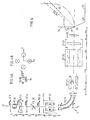
- FIG. 1 shows that two parallel beams corresponding to the energies V ⁇ ⁇ V, focus at the same point on the plane PF 35; the ordinate is dilated to make the figure legible.
- FIG. 2A shows in the radial plane a parallel beam leaving the quadrupole QP 26.
- FIG. 2C shows that the QP quadrupole 26, on the contrary, has a diverging action in vertical section. This divergent action is in turn compensated for by an electrostatic lens with slits LF 27. At the output thereof, there is therefore also a parallel beam, which crosses exactly the small dimension of the opening slit FO 29.
- the particle beam is parallel in its two transverse dimensions, downstream of the slit lens LF 27, until it is applied to the input face 31 of the magnetic sector SM 30.
- the electrostatic sector SE 23 and the magnetic sector SM 30 each have a respective virtual chromatic rotation center.
- chromatic is used here in relation to the energy dispersion.
- the particles following the central trajectory before entering the electrostatic sector and having an energy slightly different from the nominal energy of the beam will leave the electrostatic sector SE 23 with inclined trajectories. When the energy varies, these inclined trajectories seem to rotate around a point which is called the center of chromatic rotation.
- the magnetic sector SM 30 has a center of chromatic rotation, towards which particles with similar energies and the same mass must converge with the appropriate angle so that they end up after deviation, at the same point of the focal plane PF 35 and with the same angle (trajectories combined) whatever the energy in the ⁇ AV band.
- means are provided for combining the two respective chromatic centers of rotation of the electrostatic sector SE 23 and the magnetic sector SM 30.
- the quadrupole QP 26 can do this in a very simple manner with magnification appropriate. This allows a complete correction of the chromatic or energetic dispersion of the particle beam for a mass, the quadrupole being moreover arranged to provide for the other masses, trajectories of different energies with the appropriate inclination.
- FIGS. 1, 2A, 2B, 3A and 3B Reference will first be made to FIGS. 1, 2A, 2B, 3A and 3B for the description of the transfer optics as well as of the input of the spectrometer 2.
- the beam of charged particles applied to the input of the transfer optic 1 is presented with a necking at point S.
- This beam of ions is composed of particles of different masses, which are animated by slightly different kinetic energies.
- V their average kinetic energy, which is prime in electron volts, and ⁇ AV the energy dispersion.
- the beam has in principle a symmetry of revolution at the point S.
- Such a beam can consist of secondary ions emitted by a sample subjected to a primary ion beam concentrated on its surface.
- a first unipotential electrostatic lens LE 11 gives an image of the source point S at a point 51.
- PC plates 12 can be provided allowing the beam to be recentered on the optical axis.
- a lens with slots LF 13 is provided.
- FIGS. 2A and 3A show that this slotted lens has no effect on the trajectories of ions situated in the radial plane.
- the slotted lens LF 13 makes these trajectories converge at a point of necking S2.
- a second LE 14 electrostatic lens is placed after the LF 13 slit lens.
- the lens LE 14 gives points S and 51 an image P situated at the level of the entry slit FE 20 and centered on the axis of the latter.
- the lens LE 14 is placed so that its focus is substantially at point S2, this lens therefore providing sensitive rays or trajectories. ment parallel extending along the FE 20 input slot, according to its large dimension ( Figure 3B).
- magnification at the level of the entry slit FE 20 in the radial plane is obtained by playing on the excitation potential of the electrostatic lenses LE 11 and LE 14.
- a converging electrostatic lens denoted PA 21, which allows a controlled post-acceleration, and then a first HP hexapole 22.
- the PA lens 21 acts, in the vertical section of the particle beam, to produce a necking thereof at a point located upstream of the electrostatic sector SE 23.
- the first hexapole HP 22 is centered at this necking.
- This HP hexapole 22 is arranged to compensate for the second order opening aberrations created by the electrostatic sector SE 23 for the trajectories located in the radial plane. At first order, it has no action, and therefore does not modify the trajectories located in vertical section. Furthermore, as already indicated, the hexapole does not introduce b 2 type aberrations on the trajectories in the vertical section thanks to the fact that the necking of the beam in this section is located in the center of the hexapole .
- the PA 21 post-acceleration lens plays another role. This role consists in modifying the opening angle for the spectrometer 2 proper. Correlatively, seen for the rest of the spectrometer, the necking produced by the transfer optic in P at the level of the entry slit in the radial plane, is transferred to P1 by the post-acceleration lens PA 21. This makes it possible to '' increase the clarity of the spectrometer after removing or correcting the most important aberrations. Post-acceleration brings ions from V energy to Vp energy.
- the main-object plane of the post-acceleration lens PA 21 is located in the plane of the entrance slit FE 20, so that the spectrometer sees an entrance slit located at P1, in the main plane image of the PA 21 lens.
- the size of the Gaussian image has not changed. For a given separating power, only the opening angle available at the entrance increases.
- the spectrometer is arranged so that the image focal point of the post-acceleration lens PA 21 is located in the center of the HP hexapole 22, at point P2.
- Post-acceleration also makes it possible to reduce the relative energy dispersion from AVN to AVNp, which leads to a decrease in mixed aberrations and aberrations in (AVNP) 2.
- the Applicants have chosen the ratio VNp of the order of a quarter, which implies, for negative ions of incident energy of ⁇ 5 kV, to put all the conductors constituting the spectrometer and located downstream of the PA 21 post-acceleration lens at a voltage of ⁇ 15 kV.
- the spectrometer comprises a second hexapole (HP 25), arranged after the electrostatic sector (SE 23), and centered on the real image which the electrostatic sector (SE 23) of the slot (FE 20) gives in the radial plane. .
- HP 25 is centered on P3 allows correction of mixed aberrations to be carried out without having to touch up the setting of the hexapole HP 22 which corrects opening aberrations (independence of the settings).
- the energy filtering is carried out upstream of the transfer optic.
- the second HP 25 hexapole In a variant, it is carried out at the level of the second HP 25 hexapole. The latter then comprises two hexapoles framing an energy filtering slot (not shown).
- FIGS. 1, 2A, 2C, 2D show certain details of the structure of the magnetic sector. This comprises a magnet, not shown, which cooperates with two pole pieces 32A and 32B, the shape of which is given by the views illustrated in the radial plane.
- the invention makes it possible to considerably facilitate these corrections, by effecting them by adjustments which do not require displacement of the components of the spectrometer, and which are made as independent as possible from each other. .
- the particle separator of the invention would make it possible, like a spectrograph, to use a photographic plate for the collection of particles deviated, and having undergone mass analysis.
- a series of separate collecting devices such as electronic multipliers whose input surface will be sensitive to the impact of charged particles from the magnetic sector SM 30 .
- the half-angle at the top is of the order of 10 -2 radians for a separating power M / AM of the order of 4,000.
- the magnetic circuit is at ground potential, but non-magnetic electrodes placed inside the air gap are brought to a potential of + 15 kV in operation in post-accelerated mode. Finally, a magnetic shunt limits the leakage of the field on the entry face of the magnetic sector.
- a mufticollector assembly consisting of ion-electron converters followed by electron multipliers.
- the optical elements (except the magnet) are placed in a structural piece of stainless steel which ensures the mechanical positions of the various devices and serves as a vacuum enclosure.
- a cryogenic pumping unit makes it possible to obtain the desired ultra-vacuum.
- the magnet is connected to the previous device by an elastic and sealed system, which includes means for mechanical alignment of the optical axes.
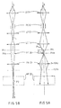
- FIGS. 5A and 5B, and 6A and 6B for a better illustration of the operations with and without post-acceleration, respectively.
- FIG. 5A shows that, in the radial plane, the trajectories pass without alteration through the slit lens LF 13, to join the second electrostatic lens LE 14, and focus in principle at point P.
- the post-acceleration lens PA 21 brought to 10 kV, produces a focal point apparent at point P1, downstream of the spectrometer. It is therefore from this point P1 that the trajectories applied to the HP hexapole 22 will start.
- the distance between points P1 and P, or more exactly between the planes PHi and PHO is 11 mm .
- the settings of the transfer optics are modified so that the trajectories begin to converge as soon as they exit the second electrostatic lens LE 14. They pass through the entry slit FE 20, to further converge a little more at the level of the lens PA 21, and lead fially to the same point of necking P2 as previously.
Description
L'invention concerne un séparateur de particules chargées, ou spectromètre de masse, à grande clarté, pour l'identification et la mesure simutta- née de plusieurs éléments.The invention relates to a charged clarity particle separator or mass spectrometer for the identification and simultaneous measurement of several elements.
Le spectromètre est destiné à recevoir un faisceau de particules chargées ou ions, composé par des particules de différentes masses (M - M1, M2, Kt, etc.), animées par des énergies cinétiques légèrement différentes. On notera V(eV) leur énergie cinétique moyenne et ± AV la dispersion énergétique correspondante.The spectrometer is intended to receive a beam of charged particles or ions, composed by particles of different masses (M - M 1 , M 2 , Kt, etc.), animated by slightly different kinetic energies. We denote by V (eV) their average kinetic energy and ± AV the corresponding energy dispersion.
Un spectromètre de masse comporte généralement une fente d'entrée, après laquelle le faisceau passe dans un secteur électrostatique, puis dans un secteur magnétique. Cette disposition a pour but de dévier les particules, d'une manière sélective quant à leur masse et autant que possible indépendamment de leur énergie. La déviation intervient dans un plan dit radial qui est le plan de symétrie de l'instrument et qui est perpendiculaire à la grande dimension de la fente d'entrée.A mass spectrometer generally has an entrance slit, after which the beam passes into an electrostatic sector, then into a magnetic sector. The purpose of this arrangement is to deflect the particles, in a selective manner as to their mass and as much as possible independently of their energy. The deviation occurs in a so-called radial plane which is the plane of symmetry of the instrument and which is perpendicular to the large dimension of the entry slit.
Le faisceau de particules présente donc une composante radiale, et une composante perpendiculaire, dans ce qu'on appelle la section verticale.The particle beam therefore has a radial component, and a perpendicular component, in what is called the vertical section.
Il est connu d'utiliser un secteur magnétique qui possède une face d'entrée et une face de sortie planes, et dans lequel la face d'entrée est inclinée sur l'axe du faisceau de particules, tandis que le plan de la face de sortie passe par l'intersection de cette face d'entrée avec l'axe du faisceau de particules. Dans ces conditions, l'angle de déviation des particules dans le secteur magnétique ne dépend pas de la masse des particules chargées, ce qui introduit une simplification. Le rayon de courbure des trajectoires dépend de la masse des particules.It is known to use a magnetic sector which has a plane entry face and exit face, and in which the entry face is inclined on the axis of the particle beam, while the plane of the face of exit passes through the intersection of this entry face with the axis of the particle beam. Under these conditions, the angle of deflection of the particles in the magnetic sector does not depend on the mass of the charged particles, which introduces a simplification. The radius of curvature of the trajectories depends on the mass of the particles.
La qualité d'un spectromètre de masse se définit par son pouvoir séparateur M/AM, où AM est la plus petite différence de masse que l'on peut distinguer avec l'instrument. Dans un spectromètre dont l'optique serait parfaite (le mot "optique" est utilisé ici au sens large), ce pouvoir séparateur ne dépendrait que des dimensions de la fente d'entrée. Dans la réalité, les images de la fente d'entrée, ou raies, sont déformées par les défauts optiques de l'appareil, dits aberrations. Ces aberrations dépendent principalement de la dispersion énergétique AV des ions, et de l'ouverture du faisceau qui est limité par la fente d'ouverture que l'on insère la plupart du temps avant le secteur magnétique.The quality of a mass spectrometer is defined by its separating power M / AM, where AM is the smallest difference in mass that can be distinguished with the instrument. In a spectrometer whose optics would be perfect (the word "optics" is used here in the broad sense), this separating power would only depend on the dimensions of the entrance slit. In reality, the images of the entry slit, or lines, are distorted by the optical defects of the device, called aberrations. These aberrations depend mainly on the energy dispersion AV of the ions, and on the beam opening which is limited by the opening slit which is inserted most of the time before the magnetic sector.
Pour un pouvoir séparateur donné, le meilleur spectromètre est le plus sensible, c'est-à-dire celui qui accepte le faisceau dont l'étendue géométrique est la plus grande. Cette aptitude est appelée "clarté" du spectromètre. Cependant, pour une géométrie donnée du spectromètre, on ne peut augmenter la clarté qu'en réduisant l'effet néfaste des aberrations.For a given separating power, the best spectrometer is the most sensitive, that is to say the one that accepts the beam with the greatest geometric extent. This ability is called "clarity" of the spectrometer. However, for a given geometry of the spectrometer, clarity can only be increased by reducing the harmful effect of aberrations.
Enfin, lorsque l'on veut faire des mesures simultanées sur toutes les raies du spectre (toutes les masses), la correction ou l'élimination des aberrations est beaucoup plus délicate.Finally, when one wants to make simultaneous measurements on all the lines of the spectrum (all the masses), the correction or elimination of the aberrations is much more delicate.
Le problème est donc de réaliser un spectromètre de masse à grande clarté, capable de détection multiple simultanée et qui possède un pouvoir séparateur élevé.The problem is therefore to produce a mass spectrometer with high clarity, capable of simultaneous multiple detection and which has a high separating power.
A cet effet, un premier but de la présente invention est de corriger les aberrations propres du spectromètre, en particulier de son secteur magnétique, et aussi de son secteur électrostatique.To this end, a first object of the present invention is to correct the proper aberrations of the spectrometer, in particular of its magnetic sector, and also of its electrostatic sector.
Un second but de la présente invention est, à l'aide d'une optique de transfert placée en amont du spectromètre de masse proprement dit, d'améliorer l'adaptation et le transfert du faisceau d'ions sur l'entrée du spectromètre.A second object of the present invention is, using a transfer optic placed upstream of the mass spectrometer itself, to improve the adaptation and the transfer of the ion beam on the input of the spectrometer.
Ces buts sont atteints par différents aspects de l'invention, dont certains sont intéressants en eux-mêmes.These aims are achieved by different aspects of the invention, some of which are interesting in themselves.
De manière connue, le dispositif ici proposé comprend une-fente d'entrée, suivie d'un secteur électrostatique, puis d'un secteur magnétique. Une fente d'ouverture peut être insérée entre les secteurs électrostatique et magnétique ou, d'une manière classique, à l'entrée du secteur électrostatique. Cet ensemble permet de dévier un faisceau de particules dans le plan radial perpendiculaire à la grande dimension de la fente d'entrée. Pour ce qui le concerne, le secteur magnétique possède une face d'entrée plane, inclinée sur l'axe du faisceau de particules, et une face de sortie également plane, dont le plan passe par l'intersection de la face d'entrée avec l'axe du faisceau de particules. Il s'agit ici de la disposition des faces magnétiques effectives qui diffèrent des faces matérielles en raison des champs de fuite.In known manner, the device proposed here comprises an inlet slot, followed by an electrostatic sector, then a magnetic sector. An opening slot can be inserted between the electrostatic and magnetic sectors or, in a conventional manner, at the entrance to the electrostatic sector. This assembly makes it possible to deflect a beam of particles in the radial plane perpendicular to the large dimension of the entry slit. As far as it is concerned, the magnetic sector has a planar entry face, inclined on the axis of the particle beam, and an exit face also planar, the plane of which passes through the intersection of the entry face with the axis of the particle beam. This is the arrangement of the actual magnetic faces which differ from the material faces due to the leakage fields.
Par ailleurs, il est également connu, dans un contexte particulier, d'interposer un quadrupôle entre les secteurs électrostatique et magnétique (publication H. MATSUDA, MASS SPECTRO-METRY REVIEWS, Vol. 2, n° 2 (1983) John Wi- lev pages 289 à 325). Toutefois, ce quadrupôle fonctionne très différemment de celui que peut utiliser la présente invention.Furthermore, it is also known, in a particular context, to interpose a quadrupole between the electrostatic and magnetic sectors (publication H. MATSUDA, MASS SPECTRO-METRY REVIEWS, Vol. 2, n ° 2 (1983) John Wi-lev pages 289 to 325). However, this quadrupole operates very differently from that which the present invention can use.
Enfin, on connaît aussi les spectrographes de masse du type Mattauch-Herzog, dans lesquels l'ouverture d'une part et la largeur de bande d'énergie d'autre part sont délimitées respectivement à l'aide d'un diaphragme d'ouverture et d'un "diaphragme d'énergie" dont les réglages interagissent. Il faut alors réduire les domaines de variation de l'ouverture et de la largeur de la bande d'énergie à des valeurs relativement faibles, si l'on veut que les aberrations du second ordre demeurent négligeables. Il en résulte une faible valeur pour la transmission ou clarté de l'appareil.Finally, there are also known mass spectrographs of the Mattauch-Herzog type, in which the aperture on the one hand and the energy bandwidth on the other are delimited respectively using an aperture diaphragm and an "energy diaphragm" whose settings interact. It is then necessary to reduce the ranges of variation of the opening and the width of the energy band to relatively small values, if it is desired that the second order aberrations remain negligible. This results in a low value for the transmission or clarity of the device.
Dans le Brevet français publié sous le No 2 056 163 (US-A-3 622 781), il est proposé de transformer un spectrographe de masse du type Mattauch-Herzog, de façon à permettre un réglage indépendant de l'ouverture et de la largeur de bande d'énergie, tout en obtenant une valeur plus élevée pour la clarté de l'appareil.In the French patent published under No. 2,056,163 (US-A-3,622,781), it is proposed to transform a mass spectrograph of the Mattauch-Herzog type, so as to allow independent adjustment of the aperture and the energy bandwidth, while obtaining a higher value for the clarity of the device.
Le moyen préconisé par ce Brevet français antérieur consiste à disposer une première lentille électrique (18) entre la fente d'entrée (10) et le diaphragme d'énergie (20) et une seconde lentille électrique (22) entre le diaphragme d'énergie (20) et le secteur magnétique (24). Le Brevet précise le rôle de ces lentilles, en relation avec le diaphragme d'ouverture et le diaphragme d'énergie réglable.The means recommended by this prior French patent consists of having a first lens electric (18) between the entrance slit (10) and the energy diaphragm (20) and a second electric lens (22) between the energy diaphragm (20) and the magnetic sector (24). The Patent specifies the role of these lenses, in relation to the aperture diaphragm and the adjustable energy diaphragm.
Dans un exemple de réalisation que donne ce Brevet français antérieur (page 8), la face d'entrée du secteur magnétique (24) est inclinée d'un angle e qui se trouve être égal à 26,6°. Cet usage d'une face d'entrée inclinée, bien connu par ailleurs, permet de définir un point focal qui se trouve à une distance de deux fois le rayon dans la direction perpendiculaire au plan de symétrie de l'appareil. Le plan (26) de focalisation est décalé en arrière du champ magnétique, d'un angle ω qui est ici égal à 8,1°.In an exemplary embodiment given by this prior French patent (page 8), the input face of the magnetic sector (24) is inclined by an angle e which happens to be equal to 26.6 °. This use of an inclined entry face, well known elsewhere, makes it possible to define a focal point which is at a distance of twice the radius in the direction perpendicular to the plane of symmetry of the device. The focusing plane (26) is offset behind the magnetic field, by an angle ω which is here equal to 8.1 °.
La valeur de 26,6° pour l'angle e correspond à une déviation standard dé 90° de l'aimant. Bien entendu, une valeur différente de l'angle de déviation donne une autre valeur pour l'angle E du Brevet français antérieur.The value of 26.6 ° for angle e corresponds to a standard deviation of 90 ° from the magnet. Of course, a value different from the deflection angle gives another value for the angle E of the prior French patent.
Il se trouve que cette valeur de 26,6° est proche de celle que va retenir la présente invention, pour d'autres raisons, et avec un secteur magnétique recevant un faisceau de particules qui est parallèle dans le plan radial.It turns out that this value of 26.6 ° is close to that which the present invention will retain, for other reasons, and with a magnetic sector receiving a particle beam which is parallel in the radial plane.
Cependant, dans le Brevet français antérieur No 2 056 163, il existe une focalisation "dans l'autre sens": alors que dans un spectrographe de masse normal les particules qui montent sont perdues, dans le Brevet antérieur les lentilles les ramènent en empêchant le faisceau de s'écarter. Il apparaît donc ainsi que l'inclinaison de la face d'entrée du spectrographe est utilisée dans le Brevet antérieur pour resserrer le faisceau, et non pour corriger les aberrations, comme le fera la présente invention.However, in the previous French patent No 2,056,163, there is a focus "in the other direction": while in a normal mass spectrograph the particles which go up are lost, in the previous patent the lenses bring them back preventing the beam to move away. It therefore appears that the inclination of the entry face of the spectrograph is used in the prior patent to tighten the beam, and not to correct the aberrations, as the present invention will do.
Selon une première caractéristique de la présente invention, le spectromètre comporte des moyens tels qu'un quadrupôle ayant un foyer objet au niveau de l'image réelle que donne le secteur électrostatique de la fente d'entrée dans le plan radial, pour fournir au secteur magnétique un faisceau de particules qui est parallèle au moins dans le plan radial, et qui présente, en outre, pour chaque énergie de la bande ± AV, l'inclinaison appropriée pour que le secteur magnétique ait un fonctionnement achromatique au niveau de toutes les raies du spectre de masse. De plus, e notant l'angle de la face d'entrée avec la normale à l'axe du faisceau qui est située du côté de la déviation de celui-ci, et 0 notant l'angle de déviation du faisceau dans le secteur magnétique, ces deux angles satisfont la relation: tg θ/2 tg (θ - ε) = 2 Ceci permet d'annuler les aberrations d'ouverture du second ordre créées par le secteur magnétique pour les trajectoires du faisceau situées dans le plan radial (aberrations en a2, où a est l'inclinaison d'une trajectoire dans le plan radial par rapport à la trajectoire centrale). Bien entendu, l'annulation de ces aberrations intervient aussi pour la composant radiale des trajectoires qui possèdent aussi une composante verticale. Les trajectoires dans la section verticale (ou les composantes, dans la section verticale de trajectoires quelconques) produisent également des aberrations d'ouverture du second ordre dans le plan radial (aberrations en b2, où b est l'inclinaison d'une trajectoire par rapport au plan radial).According to a first characteristic of the present invention, the spectrometer comprises means such as a quadrupole having an object focus at the level of the real image that the electrostatic sector of the entry slot gives in the radial plane, to supply the sector magnetic a beam of particles which is parallel at least in the radial plane, and which has, moreover, for each energy of the band ± AV, the appropriate inclination so that the magnetic sector has an achromatic functioning at the level of all the lines of the mass spectrum. In addition, e noting the angle of the entry face with the normal to the axis of the beam which is situated on the deflection side thereof, and 0 noting the angle of deflection of the beam in the magnetic sector , these two angles satisfy the relation: tg θ / 2 tg (θ - ε) = 2 This makes it possible to cancel the second order opening aberrations created by the magnetic sector for the beam trajectories located in the radial plane (aberrations in a 2 , where a is the inclination of a trajectory in the radial plane with respect to the central trajectory). Of course, the cancellation of these aberrations also occurs for the radial component of the trajectories which also have a vertical component. The trajectories in the vertical section (or the components, in the vertical section of any trajectories) also produce second order opening aberrations in the radial plane (aberrations in b 2 , where b is the inclination of a trajectory by relative to the radial plane).
Une seconde caractéristique de l'invention fait intervenir l'optique de transfert. Celle-ci est disposée en coopération avec le spectromètre proprement dit, de sorte qu'en sa section verticale, le faisceau de particules comporte une striction entre la fente d'entrée et le secteur électrostatique; il est alors prévu, au niveau de cette striction, un premier hexapôle, agencé pour compenser les aberrations d'ouverture du second ordre créées par le secteur électrostatique pour les trajectoires situées dans le plan radial, aberrations en a2, et pour la composante radiale des autres trajectoires. L'emplacement choisi pour l'hexapôle fait que ce dernier n'introduit pas d'aberrations en b2 venant de l'ouverture dans la section verticale.A second characteristic of the invention involves the transfer optic. This is arranged in cooperation with the spectrometer itself, so that in its vertical section, the particle beam has a neck between the entrance slit and the electrostatic sector; there is then provided, at this necking, a first hexapole, arranged to compensate for the second order opening aberrations created by the electrostatic sector for the trajectories located in the radial plane, aberrations at a 2 , and for the radial component other trajectories. The location chosen for the hexapole means that the latter does not introduce ab 2 aberrations from the opening in the vertical section.
Les aberrations d'ouverture du second ordre liées au secteur électrostatique sont déterminables, ce secteur étant par exemple de type sphérique.Second order opening aberrations related to the electrostatic sector can be determined, this sector being for example of the spherical type.
De préférence, l'optique de transfert est agencée pour appliquer à la fente d'entrée un faisceau de particules qui est sensiblement parallèle en section verticale. Il est prévu une lentille convergente entre la fente d'entrée et le premier hexapôle (cette lentille convergente étant capable de fournir une post-accélération). L'hexapôle est centré sur le point conjugué de la fente d'entrée par ladite lentille convergente, dans la section verticale du faisceau.Preferably, the transfer optic is arranged to apply a particle beam which is substantially parallel in vertical section to the entry slit. A converging lens is provided between the entry slit and the first hexapole (this converging lens being capable of providing post-acceleration). The hexapole is centered on the conjugate point of the entry slit by said converging lens, in the vertical section of the beam.
Selon un autre aspect de l'invention, l'optique de transfert comporte deux lentilles électrostatiques, coopérant pour produire une striction du faisceau au niveau de la fente d'entrée dans le plan radial. Entre ces deux lentilles électrostatiques est prévue une lentille à fentes agencée de sorte que le faisceau soit parallèle en section verticale au niveau de la fente d'entrée. C'est alors la lentille convergente (de post-accélération), qui assure la convergence du faisceau au point de striction précité, en section verticale.According to another aspect of the invention, the transfer optic comprises two electrostatic lenses, cooperating to produce a constriction of the beam at the level of the entry slot in the radial plane. Between these two electrostatic lenses is provided a lens with slits arranged so that the beam is parallel in vertical section at the level of the entry slit. It is then the converging (post-acceleration) lens, which ensures the convergence of the beam at the abovementioned point of necking, in vertical section.
Ce qui précède intéresse la correction des aberrations d'ouverture pour les trajectoires situées dans le plan radial, au niveau du secteur magnétique puis du secteur électrostatique. Pour les trajectoires (ou les composantes de trajectoires) dans la section verticale, il n'y a cas correction des aberrations d'ouverture en b . Toutefois, l'optique de transfert est agencée de telle sorte que les angles vus b par le spectromètre sont toujours très petits, si bien que les aberrations correspondantes en b2 sont négligeables.The above concerns the correction of the opening aberrations for the trajectories located in the radial plane, at the level of the magnetic sector then of the electrostatic sector. For trajectories (or trajectory components) in the vertical section, there is no correction of the opening aberrations in b. However, the transfer optic is arranged so that the angles seen b by the spectrometer are always very small, so that the corresponding aberrations in b 2 are negligible.
Un autre aspect encore de l'invention intéresse la correction des aberrations chromatiques, c'est-à-dire dans la dispersion énergétique.Yet another aspect of the invention concerns the correction of chromatic aberrations, that is to say in energy dispersion.
Le secteur électrostatique et le secteur magnétique possédant des centres de rotation chromatiques virtuels respectifs, le quadrupôle est placé de manière à conjuguer avec un grandissement approprié ces deux centres de rotation chromatique. Le quadrupôle conjugue le centre de rotation chromatique du secteur électrostatique avec le centre de rotation chromatique du secteur magnétique correspondant à un rayon donné, c'est-à-dire, à une masse donnée. Le quadrupôle est en outre disposé de manière à ce que chaque énergie arrive sur le secteur magnétique avec l'inclinaison appropriée; il s'ensuit que la dispersion chromatique est complètement annulée pour la masse considérée après la sortie du secteur magnétique tandis que pour les autres masses la dispersion chromatique s'annule au niveau de leur raie. Cette correction intervient dans la limite de la bande d'énergie ± ΔV définie par les moyens disposés en amont de l'optique de transfert ou par une fente de filtrage placée en P3.The electrostatic sector and the magnetic sector having centers of rotation chro respective virtual matics, the quadrupole is placed so as to combine with an appropriate magnification these two centers of chromatic rotation. The quadrupole combines the center of chromatic rotation of the electrostatic sector with the center of chromatic rotation of the magnetic sector corresponding to a given radius, that is to say, to a given mass. The quadrupole is also arranged so that each energy arrives on the magnetic sector with the appropriate inclination; it follows that the chromatic dispersion is completely canceled for the mass considered after leaving the magnetic sector while for the other masses the chromatic dispersion is canceled at their line. This correction occurs within the limit of the energy band ± ΔV defined by the means disposed upstream of the transfer optic or by a filtering slot placed in P3.
En pratique, le quadrupôle est disposé de manière que son foyer-objet coïncide avec l'image réelle que donne le secteur électrostatique de la fente d'entrée dans le plan radial, ce quadrupôle étant suivi de moyens de compensation de sa divergence dans la section verticale, de sorte que le faisceau de particules soit ensuite parallèle en ses deux dimensions transversales. Les moyens de compensation de la divergence du quadrupôle en section verticale sont avantageusement une lentille à fentes.In practice, the quadrupole is arranged so that its focal point coincides with the real image that the electrostatic sector of the entry slot gives in the radial plane, this quadrupole being followed by means of compensating for its divergence in the section vertical, so that the particle beam is then parallel in its two transverse dimensions. The means for compensating for the divergence of the quadrupole in vertical section are advantageously a lens with slits.
Il existe encore des aberrations mixtes d'ouverture et chromatiques. Pour compenser celles-ci, le dispositif comporte un second hexapôle, disposé après le secteur électrostatique et sensiblement centré sur l'image réelle que donne le secteur électrostatique de la fente d'entrée dans le plan radial.There are still mixed opening and chromatic aberrations. To compensate for these, the device comprises a second hexapole, disposed after the electrostatic sector and substantially centered on the real image that the electrostatic sector of the entry slot gives in the radial plane.
Cette disposition permet la réduction des aberrations mixtes, pour les trajectoires situées dans le plan radial, avec une compensation exacte pour une masse choisie. Pour les autres masses, l'aberration est considérablement réduite.This arrangement allows the reduction of mixed aberrations, for the trajectories located in the radial plane, with exact compensation for a chosen mass. For the other masses, the aberration is considerably reduced.
Le filtrage chromatique, c'est-à-dire en énergie, du faisceau de particules, s'effectue ici en amont de l'optique de transfert. Dans une variante, il s'effectue au niveau de ce second hexapôle. Celui-ci comporte alors deux hexapôles encadrant une fente de filtrage en énergie.The chromatic, that is to say energy, filtering of the particle beam takes place here upstream of the transfer optic. In a variant, it takes place at the level of this second hexapole. This then comprises two hexapoles framing an energy filtering slot.
D'autres caractéristiques et avantages de l'invention apparaîtront à l'examen de la description détaillée ci-après, et des dessins annexés, sur lesquels:
- - la figure 1 est une première vue schématique d'un spectromètre selon la présente invention, présentée comme une coupe dans le plan radial, cette figure comportant deux faisceaux parallèles arrivant avec des incidences différentes sur le secteur magnétique, ces deux faisceaux correspondant à des énergies légèrement différentes ± AV;
- - la figure 2A est une vue semblable à la figure 1, mais illustrant la séparation, dans un même faisceau monoénergétique, de particules possédant deux masses différentes;
- - la figure 2B est une vue partielle illustrant, en section verticale, la forme du faisceau en amont du secteur électrostatique SE 23 de la figure 2A;
- - la figure 2C est une vue illustrant, encore en section verticale, la forme du faisceau en aval du secteur électrostatique SE 23; et
- - la figure 2D est une vue en section verticale illustrant la forme du faisceau dans la direction que celui-ci présente en sortie du secteur magnétique
SM 30; - - les figures 3A et 3B sont des vues agrandies correspondant aux figures 2A et 2B;
- - les figures 4, 4A et 4B illustrent plus précisément un 5 exemple particulier de réalisation du spectromètre de l'invention;
- - les figures 5A et 5B illustrent, dans cet exemple, le fonctionnement avec post-accélération; et
- - les figures 6A et 6B illustrent, dans le même exemple, le fonctionnement sans post-accélération.
- - Figure 1 is a first schematic view of a spectrometer according to the present invention, presented as a section in the radial plane, this figure comprising two parallel beams arriving with different incidences on the magnetic sector, these two beams corresponding to energies slightly different ± AV;
- - Figure 2A is a view similar to Figure 1, but illustrating the separation, in the same monoenergetic beam, of particles having two different masses;
- - Figure 2B is a partial view illustrating, in vertical section, the shape of the beam upstream of the
electrostatic sector SE 23 of Figure 2A; - - Figure 2C is a view illustrating, also in vertical section, the shape of the beam downstream of the
electrostatic sector SE 23; and - - Figure 2D is a vertical section view illustrating the shape of the beam in the direction that it presents at the output of the
magnetic sector SM 30; - - Figures 3A and 3B are enlarged views corresponding to Figures 2A and 2B;
- - Figures 4, 4A and 4B illustrate more specifically a particular embodiment of the spectrometer of the invention;
- - Figures 5A and 5B illustrate, in this example, operation with post-acceleration; and
- - Figures 6A and 6B illustrate, in the same example, operation without post-acceleration.
Comme précédemment indiqué, la présente invention concerne 15 un séparateur de particules chargees, ou spectromètre de masse, à détection multiple simultanée et à grande clarté.As previously indicated, the present invention relates to a charged particle separator, or mass spectrometer, with multiple simultaneous detection and high clarity.
Par opposition aux spectrographes de masse, qui utilisent comme détecteur final une plaque photographique, les spectromètres de masse n'ont pas nécessairement besoin que leur zone de détection, la surface focale de sortie du secteur magnétique, soit un plan.In contrast to mass spectrographs, which use a photographic plate as their final detector, mass spectrometers do not necessarily need their detection zone, the focal exit surface of the magnetic sector, to be a plane.
Il en est cependant ainsi dans le spectromètre de l'invention, 25 que l'on décrira tout d'abord d'une manière générale en référence aux figures 1 et 2.However, this is the case in the spectrometer of the invention, which will be described first of all in general with reference to FIGS. 1 and 2.
Le spectromètre comporte à son entrée une optique de transfert 1. La nature de celle-ci peut dépendre des caractéristiques du faisceau de particules appliquées à l'entrée ou "point-source" S. L'optique de transfert 1 se termine au niveau d'une fente d'entrée FE 20, qui constitue l'entrée du spectromètre de masse proprement dit.The spectrometer has at its input a
De manière connue, le spectromètre comporte, derrière la fente d'entrée FE 20, un secteur électrostatique SE 23, puis un secteur magnétique SM 30, en amont duquel est prévue une fente d'ouverture FO 29. Cet ensemble de moyens a pour fonction de dévier le faisceau de particules dans un plan radial perpendiculaire à la grande dimension de la fente d'entrée FE 20. Le plan radial est celui des figures 1 et 2A.In a known manner, the spectrometer comprises, behind the entry slit
On sait que l'organe principal d'un spectromètre de masse est son secteur magnétique, dont l'action dispersive dépend à la fois de la masse et de l'énergie de chaque particule; cette action dispersive se manifeste par des trajectoires en arc de cercle, dont le rayon est plus ou moins grand selon la masse et l'énergie. Il est connu d'associer à un tel secteur magnétique un secteur électrostatique qui le précède, et qui possède de son côté une action dispersive mais uniquement en fonction de l'énergie des particules. Les deux secteurs sont combinés de telle sorte que l'action dispersive du secteur électrostatique compense l'action dispersive en énergie du secteur magnétique. Il ne reste alors en principe, en sortie du secteur magnétique, que l'action dispersive en fonction de la masse.We know that the main organ of a mass spectrometer is its magnetic sector, whose dispersive action depends on both the mass and the energy of each particle; this dispersive action manifests itself by trajectories in an arc of a circle, the radius of which is greater or less depending on mass and energy. It is known to associate with such a magnetic sector an electrostatic sector which precedes it, and which for its part has a dispersive action but only as a function of the energy of the particles. Both sectors are combined so that the dispersive action of the electrostatic sector compensates for the energy dispersive action of the magnetic sector. It then remains in principle, at the exit from the magnetic sector, only the dispersive action as a function of mass.
Par ailleurs, et bien que cela ne soit pas classique, la publication Matsuda déjà citée montre l'utilisation d'un quadrupôle entre le secteur électrostatique et le secteur magnétique. Cela est donc également considéré comme connu, étant observé que le quadrupôle de Matsuda n'a pas du tout la même fonction que celui de la présente invention.Furthermore, and although this is not classic, the publication Matsuda already cited shows the use of a quadrupole between the electrostatic sector and the magnetic sector. This is therefore also considered to be known, it being observed that the Matsuda quadrupole does not at all have the same function as that of the present invention.
Enfin, il est également connu de faire en sorte que le secteur magnétique SM 30 possède une face d'entrée plane 31, inclinée sur l'axe du faisceau de particules, et une face de sortie 32 également plane, dont le plan passe par l'intersection 33 de la face d'entrée 31 avec l'axe du faisceau de particules. Cette disposition présente l'avantage de fournir le même angle de déviation quelle que soit la masse. L'angle de déviation est égal au double de l'angle de la face de sortie 32 avec l'axe du faisceau des particules à l'entrée du secteur magnétique SM 30. Il en résulte encore que, pour un faisceau parallèle à l'entrée, la focalisation des particules en sortie du secteur magnétique s'effectue dans un plan PF 35 qui passe lui aussi par le point 33.Finally, it is also known to ensure that the
Pour obtenir un spectromètre à détection multiple et à grande clarté, en même temps qu'à grand pouvoir séparateur (ou excellente résolution), il est nécessaire de compenser différentes aberrations que présentent les éléments du spectromètre, pris séparément ou dans leurs combinaisons.To obtain a spectrometer with multiple detection and with great clarity, at the same time as with great separating power (or excellent resolution), it is necessary to compensate for various aberrations which the elements of the spectrometer present, taken separately or in their combinations.
Une première aberration est connue sous le nom d'aberration d'ouverture du second ordre du secteur magnétique. En bref, ce type d'aberration réside en ce que deux trajectoires symétriques par rapport à la trajectoire centrale à l'entrée du secteur magnétique se couperont après le secteur en un point situé hors de cette trajectoire centrale; le décalage entre le point d'intersection et la trajectoire centrale est proportionnel au carré de l'inclinaison angulaire a de chacune des trajectoires sécantes par rapport à la trajectoire centrale (d'où le second ordre en a2).A first aberration is known as a second order aperture aberration of the magnetic sector. In short, this type of aberration lies in the fact that two symmetrical trajectories with respect to the central trajectory at the entrance to the magnetic sector will intersect after the sector at a point situated outside this central trajectory; the offset between the point of intersection and the central trajectory is proportional to the square of the angular inclination a of each of the intersecting trajectories relative to the central trajectory (hence the second order in a 2 ).
Un premier aspect de l'invention consiste à corriger ce type d'aberration d'ouverture du second ordre, au niveau du secteur magnétique lui-même. On désigne par 34 la normale à l'axe du faisceau de particules qui est située du côté de la concavité qui sera imprimée au faisceau par le secteur magnétique SM 30. On note par e l'angle que forme la face d'entrée 31 du secteur magnétique SM 30 avec cette normale 34. On note par 8 l'angle de déviation du faisceau dans le secteur magnétique SM 30. De manière tout à fait inattendue, il a été observé par les inventeurs que les aberrations d'ouverture du second ordre créées par le secteur magnétique, pour les trajectoires situées dans le plan radial, sont annulées lorsque ces deux angles satisfont la relation suivante: tg θ/2 · tg (θ - ε) = 2A first aspect of the invention consists in correcting this type of second order opening aberration, at the level of the magnetic sector itself. We denote by 34 the normal to the axis of the particle beam which is located on the side of the concavity which will be impressed on the beam by the
La présente invention concerne un spectromètre de masse à très grande clarté, c'est-à-dire un appareil acceptant les faisceaux dont l'étendue géométrique est la plus grande, et à détection simuftanée, ce qui rend la correction des aberrations très délicate.The present invention relates to a mass spectrometer with very high clarity, that is to say an apparatus accepting beams with the greatest geometric extent, and with simultaneous detection, which makes the correction of aberrations very delicate.
L'invention préconise une inclinaison appropriée de la face d'entrée du secteur magnétique, pour que celui-ci ait un fonctionnement dépourvu d'aberrations d'ouverture du second ordre pour toutes les masses - toutes les trajectoires du faisceau situées dans le plan radial - sous réserve bien sur qu'aient été préalablement corrigées les aberrations d'ouverture du secteur électrostatique.The invention recommends an appropriate inclination of the input face of the magnetic sector, so that it has an operation devoid of second order aperture aberrations for all masses - all beam trajectories located in the radial plane - provided of course that the aberrations in the opening of the electrostatic sector have been corrected beforehand.
L'inclinaison e de la face d'entrée est, en fonction de l'angle de déviation 9 du secteur magnétique, donnée par la relation précitée:
- tg θ/2 . tg (θ - ε) = 2
- tg θ / 2. tg (θ - ε) = 2
Pour une déviation de 90° dans le secteur magnétique SM, on aboutit à tg e = 112 soit e - 26,56°.For a deviation of 90 ° in the magnetic sector SM, we arrive at tg e = 112, ie e - 26.56 °.
Cette relation a été établie à partir des travaux des Demandeurs, sur la base des coefficients d'aberrations qui se manifestent dans les secteurs magnétiques pour de nombreuses configurations. En combinant certains de ces coefficients d'aberrations, on a pu trouver la relation ci-dessus, pour laquelle sont corrigées les aberrations d'ouverture du second ordre du secteur magnétique. C'est le point principal, qui permet de corriger ces aberrations quelle que soit l'étendue géométrique du faisceau, ce qui est indispensable dès lors que la présente invention vise à collecter un faisceau aussi large que possible.This relationship was established from the work of the Applicants, on the basis of the aberration coefficients which occur in the magnetic sectors for many configurations. By combining some of these aberration coefficients, we could find the above relationship, for which the second order aperture aberrations of the magnetic sector are corrected. This is the main point, which makes it possible to correct these aberrations whatever the geometric extent of the beam, which is essential as soon as the present invention aims to collect a beam as wide as possible.
Il demeure bien entendu l'effet secondaire que l'inclinaison de la face d'entrée dégage le plan de focalisation (PF 35) du champ magnétique de l'aimant, chose antérieurement connue.There remains of course the secondary effect that the inclination of the input face releases the focusing plane (PF 35) from the magnetic field of the magnet, something previously known.
Il a été observé que le Brevet français No 2 056 163 déjà cité fait apparaître un secteur magnétique dont la face d'entrée est inclinée de 26,6° pour un angle de déviation de 90°. Toutefois, ce Brevet antérieur utilise cette disposition dans un contexte différent, et par conséquent il n'enseigne nullement à l'homme de l'art que la relation précitée puisse être utilisée pour effectuer une correction des aberrations dans le secteur magnétique. Par contre, l'utilisation de cette même relation selon la présente invention produit une correction des aberrations d'ouverture de l'aimant pour les trajectoires situées dans le plan radial, de sorte qu'il ne reste que les aberrations introduites par le secteur électrostatique, que l'on peut corriger à l'aide d'un hexapôle (HP22) situé en amont.It has been observed that the French Patent No. 2,056,163 already cited shows a magnetic sector whose entry face is inclined by 26.6 ° for a deflection angle of 90 °. However, this prior patent uses this provision in a different context, and therefore in no way teaches those skilled in the art that the aforementioned relationship can be used to correct aberrations in the magnetic sector. On the other hand, the use of this same relation according to the present invention produces a correction of the opening aberrations of the magnet for the trajectories located in the radial plane, so that only the aberrations introduced by the electrostatic sector remain. , which can be corrected using a hexapole (HP22) located upstream.
L'homme de l'art comprendra que cette correction des aberrations d'ouverture du second ordre liées au secteur magnétique lui-même est très importante, et qu'elle peut naturellement servir dans d'autres spectromètres que celui décrit en détail ici.Those skilled in the art will understand that this correction of the second order aperture aberrations linked to the magnetic sector itself is very important, and that it can naturally be used in other spectrometers than that described. in detail here.
Le faisceau de particules disponible en sortie du secteur électrostatique SE 23 présente une striction en un point P3 (figure 2A). Afin de tirer le meilleur parti de la première correction, des moyens sont prévus en aval de ce point P3 pour faire en sorte que le secteur magnétique SM 30 reçoive un faisceau de particules qui est parallèle dans le plan radial.The particle beam available at the outlet of the
Ceci peut être réalisé à l'aide d'un ou plusieurs quadrupôles tels que QP 26, interposés entre le secteur électrostatique SE 23 et le secteur magnétique SM 30. Une façon de faire consiste à agencer le quadrupôle unique QP 26 de manière que son foyer-objet coïncide avec le point de striction P3. Comme indiqué précédemment, la position du quadrupôle QP 26 est déterminée de manière que l'inclinaison de chacun des faisceaux parallèles correspondant aux diverses énergies soit appropriées pour donner un fonctionnement achromatique au niveau des raies situées dans le plan PF 35 et cela simultanément pour toutes les masses. Cette propriété est illustrée sur la figure 1 qui montre que deux faisceaux parallèles corrspondant aux énergies V ± ΔV, focalisent en un même point du plan PF 35; l'ordonnée est dilatée pour rendre la figure lisible. Comme on le verra plus loin, ce point P3 est l'image réelle que donne le secteur électrostatique SE 23 de la fente d'entrée FE 20 dans le plan radial. Ainsi, la figure 2A fait apparaître dans le plan radial un faisceau parallèle en sortie du quadrupôle QP 26.This can be done using one or more quadrupoles such as
La figure 2C montre que le quadrupôle QP 26 possède au contraire une action divergente en section verticale. Cette action divergente est à son tour compensée par une lentille électrostatique à fentes LF 27. En sortie de celle-ci, on retrouve donc aussi un faisceau parallèle, qui traverse exactement la petite dimension de la fente d'ouverture FO 29.FIG. 2C shows that the
Si maintenant on examine à nouveau la figure 2A, il apparaît que le faisceau parallèle (représenté unique et, pour simplifier la figure, comme correspondant à l'énergie moyenne du faisceau) fourni par le quadrupôle QP 26 dans le plan radial traverse sans modification la lentille à fentes LF 27, pour passer à l'intérieur de la grande dimension de la fente d'ouverture FO 29. La comparaison avec la figure 1 montre que cette grande dimension de la fente d'ouverture FO 29 permet le passage des faisceaux parallèles d'inclinaisons chromatiques diverses issus du quadrupôle QP 26, compte tenu de la dispersion énergétique existant entre le secteur électrostatique SE 23 et le secteur magnétique SM 30.If we now examine FIG. 2A again, it appears that the parallel beam (represented single and, to simplify the figure, as corresponding to the average energy of the beam) supplied by the
Des dispositions qui précèdent, il résulte finalement que le faisceau de particules est parallèle en ses deux dimensions transversales, en aval de la lentille à fentes LF 27, jusqu'à ce qu'il soit appliqué à la face d'entrée 31 du secteur magnétique SM 30.From the foregoing arrangements, it finally results that the particle beam is parallel in its two transverse dimensions, downstream of the
On sait que le secteur électrostatique SE 23 et le secteur 25 magnétique SM 30 possèdent chacun un centre de rotation chromatique virtuel respectif. (L'adjectif "chromatique" est utilisé ici en relation à la dispersion d'énergie). Les particules suivant la trajectoire centrale avant leur entrée dans le secteur électrostatique et présentant une énergie légèrement différente de l'énergie nominale du faisceau sortiront du secteur électrostatique SE 23 avec des trajectoires inclinées. Lorsque l'énergie varie, ces trajectoires inclinées paraissent tourner autour d'un point qui est nommé centre de rotation chromatique.It is known that the
De manière analogue, le secteur magnétique SM 30 possède un centre de rotation chromatique, vers lequel doivent converger avec l'angle approprié des particules présentant des énergies voisines et la même masse pour qu'elles aboutissent après déviation, au même point du plan focal PF 35 et avec le même angle (trajectoires confondues) quelle que soit l'énergie dans la bande ± AV. On obtient alors une compensation complète (au premier ordre) de la dispersion énergétique du prisme magnétique. On notera qu'il y a autant de centres de rotation chromatique qu'il y a de masses considérées.Similarly, the
Toutefois, si, à l'entrée du secteur SM 30, l'inclinaison des trajectoires est simplement proportionnelle à l'écart AV avec un facteur approprié, le même pour toutes les masses, elles seront quand même convergentes au même point du plan focal PF 35, pour une masse donnée, mais les trajectoires d'énergies différentes n'auront plus la même inclinaison.However, if, at the entrance to
Selon une autre caractéristique de l'invention, des moyens sont prévus pour conjuguer les deux centres de rotation chromatiques respectifs du secteur électrostatique SE 23 et du secteur magnétique SM 30. Le quadrupôle QP 26 peut le faire d'une manière très simple avec un grandissement approprié. Ceci permet une correction complète de la dispersion chromatique ou énergétique du faisceau de particules pour une masse, le quadrupôle étant en outre disposé pour fournir pour les autres masses, des trajectoires d'énergies différentes avec l'inclinaison appropriée.According to another characteristic of the invention, means are provided for combining the two respective chromatic centers of rotation of the
On examinera maintenant la correction des aberrations d'ouverture du second ordre qui se produisent au niveau du secteur électrostatique SE 23. Cette correction fait intervenir essentiellement un premier hexapôle HP 22. Toutefois, ce premier hexapôle HP 22 intervenant aussi en étroite combinaison avec les éléments du spectromètre 2 proprement dit ainsi que de son optique de transfert 1, il convient de décrire maintenant l'ensemble du spectromètre.We will now examine the correction of the second order opening aberrations which occur at the level of the
Il sera tout d'abord fait référence aux figures 1, 2A, 2B, 3A et 3B pour la description de l'optique de transfert ainsi que de l'entrée du spectromètre 2.Reference will first be made to FIGS. 1, 2A, 2B, 3A and 3B for the description of the transfer optics as well as of the input of the spectrometer 2.
Le faisceau de particules chargées appliqué à l'entrée de l'optique de transfert 1 se présente avec une striction au point S. Ce faisceau d'ions est composé de particules de différentes masses, qui sont animées par des énergies cinétiques légèrement différentes. On note comme précédemment V leur énergie cinétique moyenne, qui s'exprime en électronsvolts, et ± AV la dispersion énergétique.The beam of charged particles applied to the input of the
Le faisceau présente en principe une symétrie de révolution au point S. Un tel faisceau peut être constitué par des ions secondaires émis par un échantillon soumis à un faisceau d'ions primaire concentré à sa surface.The beam has in principle a symmetry of revolution at the point S. Such a beam can consist of secondary ions emitted by a sample subjected to a primary ion beam concentrated on its surface.
Une première lentille électrostatique unipotentielle LE 11 donne une image du point de source S en un point 51. Autour de ce point peuvent être prévues des plaques PC 12 permettant le recentrage éventuel du faisceau sur l'axe optique.A first unipotential
Après la première lentille LE 11, et éventuellement les plaques de centrage PC 12, est prévue une lentille à fentes LF 13.After the
Les figures 2A et 3A montrent que cette lentille à fentes n'a aucun effet sur les trajectoires d'ions situées dans le plan radial. Par contre, en section verticale (figures 2B et 3B), la lentille à fentes LF 13 fait converger ces trajectoires en un point de striction S2.FIGS. 2A and 3A show that this slotted lens has no effect on the trajectories of ions situated in the radial plane. On the other hand, in vertical section (FIGS. 2B and 3B), the slotted
Une seconde lentille électrostatique LE 14 est placée après la lentille à fentes LF 13.A
Dans le plan radial (figures 2A et 3A), la lentille LE 14 donne des points S et 51 une image P située au niveau de la fente d'entrée FE 20 et centrée sur l'axe de celle-ci.In the radial plane (FIGS. 2A and 3A), the
Dans la section verticale (figures 2B et 3B), la lentille LE 14 est placée de façon que son foyer soit sensiblement au point S2, cette lentille fournissant donc des rayons ou trajectoires sensible. ment parallèles se déployant le long de la fente d'entrée FE 20, selon sa grande dimension (figure 3B).In the vertical section (Figures 2B and 3B), the
De cette manière, le grandissement au niveau de la fente d'entrée FE 20 dans le plan radial est obtenu en jouant sur le potentiel d'excitation des lentilles électrostatiques LE 11 et LE 14.In this way, the magnification at the level of the entry slit
Pour les trajectoire situées dans le plan vertical (figures 2B et 38), un réglage indépendant est obtenu grâce à la lentille à fentes LF 13.For the trajectories situated in the vertical plane (FIGS. 2B and 38), an independent adjustment is obtained thanks to the lens with
A l'entrée du spectromètre 2 proprement dit, et derrière la fente d'entrée FE 20, sont prévues d'une part une lentille électrostatique convergente notée PA 21, qui permet une post-accélération commandée, et ensuite un premier hexapôle HP 22.At the entrance to the spectrometer 2 proper, and behind the entry slit
La lentille PA 21 agit, dans la section verticale du faisceau de particules, pour produire une striction de celui-ci en un point situé en amont du secteur électrostatique SE 23. Le premier hexapôle HP 22 est centré au niveau de cette striction.The
Cet hexapôle HP 22 est agencé pour compenser les aberrations d'ouverture du second ordre créées par le secteur électrostatique SE 23 pour les trajectoires situées dans le plan radial. Au premier ordre, il n'a aucune action, et ne modifie donc pas les trajectoires situées en section verticale. Par ailleurs, comme il a été déjà indiqué, l'hexapôle n'introduit pas d'aberrations du type b2 sur les trajectoires dans la section verticale grâce au fait que la striction du faisceau dans cette section se trouve au centre de l'hexapôle.This HP hexapole 22 is arranged to compensate for the second order opening aberrations created by the
La lentille de post-accélération PA 21 joue un autre rôle. Ce rôle consiste à modifier l'angle d'ouverture pour le spectromètre 2 proprement dit. Corrélativement, vue pour le reste du spectromètre, la striction que produit l'optique de transfert en P au niveau de la fente d'entrée dans le plan radial, est reportée en P1 par la lentille de post-accélération PA 21. Ceci permet d'augmenter la clarté du spectromètre après suppression ou correction des aberrations les plus importantes. La post-accélération amène les ions de l'énergie V à l'énergie Vp.The
En pratique, le plan principal-objet de la lentille de post-accélération PA 21 est situé dans le plan de la fente d'entrée FE 20, de sorte que le spectromètre voit une fente d'entrée située en P1, dans le plan principal image de la lentille PA 21. Pour le spectromètre, la dimension de l'image gaussienne n'a pas changé. Pour un pouvoir séparateur donné, seul l'angle d'ouverture disponible à l'entrée augmente.In practice, the main-object plane of the
Comme précédemment indiqué, le spectromètre est agencé pour que le foyer image de la lentille de post-accélération PA 21 se trouve au centre de l'hexapôle HP 22, au point P2.As previously indicated, the spectrometer is arranged so that the image focal point of the
La post-accélération permet, de plus, de réduire la dispersion énergétique relative de AVN à AVNp, ce qui entraine une diminution des aberrations mixtes et des aberrations en (AVNP)2.Post-acceleration also makes it possible to reduce the relative energy dispersion from AVN to AVNp, which leads to a decrease in mixed aberrations and aberrations in (AVNP) 2.
Pour des raisons de commodité, Les Demanderesses ont choisi le rapport VNp de l'ordre de un quart, ce qui implique, pour des ions négatifs d'énergie incidente de ± 5 kV, de mettre tous les conducteurs constituant le spectromètre et situés en aval de la lentille de post-accélération PA 21 à une tension de± 15 kV.For reasons of convenience, the Applicants have chosen the ratio VNp of the order of a quarter, which implies, for negative ions of incident energy of ± 5 kV, to put all the conductors constituting the spectrometer and located downstream of the
Ensuite, le spectromètre comporte un second hexapôle (HP 25), disposé après le secteur électrostatique (SE 23), et centré sur l'image réelle que donne le secteur électrostatique (SE 23) de la fente (FE 20) dans le plan radial. Ceci permet la réduction des aberrations mixtes d'ouverture et chromatique pour les trajectoires situées dans le plan radial, avec compensation exacte pour une masse choisie. Le fait que HP 25 soit centré sur P3 permet d'effectuer la correction des aberrations mixtes sans avoir à retoucher le réglage de l'hexapôle HP 22 qui corrige les aberrations d'ouverture (indépendance des réglages).Then, the spectrometer comprises a second hexapole (HP 25), arranged after the electrostatic sector (SE 23), and centered on the real image which the electrostatic sector (SE 23) of the slot (FE 20) gives in the radial plane. . This allows the reduction of mixed opening and chromatic aberrations for the trajectories located in the radial plane, with exact compensation for a chosen mass. The fact that
Dans le mode de réalisation décrit, le filtrage en énergie s'effectue en amont de l'optique de transfert.In the embodiment described, the energy filtering is carried out upstream of the transfer optic.
Dans une variante, il s'effectue au niveau du second hexapôle HP 25. Celui-ci comporte alors deux hexapôles encadrant une fente de filtrage en énergie (non représentés).In a variant, it is carried out at the level of the
Après le second hexapôle HP 25, on retrouve le quadrupôle QP 26, la lentille à fentes LF 27, la fente d'ouverture FO 29, et enfin le secteur magnétique SM 30.After the
Les figures 1, 2A, 2C, 2D font apparaitre certains détails 20 de la structure du secteur magnétique. Celui-ci comporte un aimant, non représenté, qui coopère avec deux pièces polaires 32A et 32B, dont la forme est donnée par les vues illustrées dans le plan radial.FIGS. 1, 2A, 2C, 2D show certain details of the structure of the magnetic sector. This comprises a magnet, not shown, which cooperates with two
Indépendamment de l'obtention des différentes corrections déjà décrites, l'invention permet de faciliter considérablement ces corrections, en les effectuant par des réglages qui ne nécessitent pas de déplacement des composants du spectromètre, et qui sont rendus autant que possible indépendants les uns des autres.Independently of obtaining the various corrections already described, the invention makes it possible to considerably facilitate these corrections, by effecting them by adjustments which do not require displacement of the components of the spectrometer, and which are made as independent as possible from each other. .
A cet effet, le montage et le réglage du spectromètre s'effectuent comme suit:
- - Sont implantés tout d'abord le secteur électrostatique SE 23, qui est de type sphérique, ainsi que le secteur magnétique
SM 30. - -
Le quadrupôle QP 26 est alors mis en place, pour respecter a priori la condition d'inclinaison appropriée des trajectoires chromatiques et la condition de parallélisme du faisceau entrant dans le secteur magnétique. La lentille à fentesLF 27 est ensuite mise en place, de manière à corriger la divergence du quadrupôle QP 26 dans la section verticale. La fente d'ouvertureFO 29 est elle aussi mise en place, de même que lesecond hexapôle HP 25, lequel est placé au foyer du quadrupôleQP 26. On notera au passage que la structure en section droite des hexapôlesHP 22et HP 25 est illustrée sur la figure 4A, tandis que celle du quadrupôleOP 26 est illustrée sur la figure 4B. - - En amont du secteur électrostatique SE 23, sont implantés 15 (en remontant le faisceau) l'hexapôle
HP 22, centré sur un point choisi à l'avance comme foyer en section verticale, la lentille de post-accélérationPA 21, la fente d'entréeFE 20, la seconde lentille électrostatique LE 14, la lentille à fentesLF 13, les plaques de centragePC 12, et enfin la première lentille électrostatique unipotentielle LE 11.
- - The
electrostatic sector SE 23, which is of the spherical type, is first installed, as well as themagnetic sector SM 30. - - The
quadrupole QP 26 is then set up, in order to comply a priori with the condition of appropriate inclination of the chromatic trajectories and the condition of parallelism of the beam entering the magnetic sector. The slottedlens LF 27 is then put in place, so as to correct the divergence of thequadrupole QP 26 in the vertical section. Theopening slot FO 29 is also put in place, as is thesecond hexapole HP 25, which is placed at the focus of thequadrupole QP 26. It will be noted in passing that the structure in cross section of the hexapolesHP 22 andHP 25 is illustrated in FIG. 4A, while that of thequadrupole OP 26 is illustrated in FIG. 4B. - - Upstream of the
electrostatic sector SE 23, there are located 15 (by raising the beam) thehexapole HP 22, centered on a point chosen in advance as focal point in vertical section, thepost-acceleration lens PA 21, theslot FE 20 input, thesecond LE 14 electrostatic lens, theLF 13 slotted lens, thePC 12 centering plates, and finally thefirst LE 11 unipotential electrostatic lens.
Tous les éléments peuvent ainsi être placés dans des positions fixes prédéterminées, qui n'auront pas à être modifiées par la suite.All the elements can thus be placed in predetermined fixed positions, which will not have to be modified subsequently.
Des réglages additionnels sont alors effectués comme suit :
- -
Le quadrupôle OP 26 est réglé de façon à donner une inclinaison appropriée aux trajectoires dispersées en énergie issues du secteur électrostatiqueSE 23. - - La lentille de post-accélération et ses annexes sont réglés de manière à amener le point de striction P3 au foyer du quadrupôle QP 26 et par conséquent au centre de l'hexapôle
HP 25; ce réglage assure le parallélisme dans le plan radial du faisceau issu deOP 26 et permet de compenser d'éventuels défauts de position du quadrupôleQP 26. - - La lentille à fentes
LF 13 de l'optique de transfert est réglée pour amener le point de striction P2 au centre dupremier hexapôle HP 22.
- - The
quadrupole OP 26 is adjusted so as to give an appropriate inclination to the trajectories dispersed in energy coming from theelectrostatic sector SE 23. - - The post-acceleration lens and its annexes are adjusted so as to bring the point of necking P3 to the focal point of the
quadrupole QP 26 and therefore to the center of thehexapole HP 25; this adjustment ensures parallelism in the radial plane of the beam fromOP 26 and makes it possible to compensate for possible position defects of theQP 26 quadrupole. - - The
LF 13 slot lens of the transfer optic is adjusted to bring the point of necking P2 to the center of thefirst HP 22 hexapole.
L'homme de l'art comprendra que l'appareil se trouve ainsi entièrement réglé sans qu'il n'y ait aucune nécessité de démontage pour faire varier les positions relatives des différents constituants.Those skilled in the art that the device is thus entirely solved without that there is no need i t disassembly for changing the relative positions of the various components.
Il n'y a pas non plus nécessité de réglage au niveau de la collection des particules déviées, en sortie du secteur magnétique SM 30. En effet, les particules des différentes masses arrivent toutes sur un même plan PF 35.There is also no need for adjustment at the level of the collection of deflected particles, at the outlet of the
Le séparateur de particules de l'invention permettrait, à la façon d'un spectrographe, d'utiliser une plaque photographique pour la collection des particules déviées, et ayant subi l'analyse en masse.The particle separator of the invention would make it possible, like a spectrograph, to use a photographic plate for the collection of particles deviated, and having undergone mass analysis.
Selon l'invention, il est estimé préférable de placer dans le plan focal PF 35 une série de dispositifs collecteurs séparés, tels que des multiplicateurs électroniques dont la surface d'entrée sera sensible à l'impact des particules chargées issues du secteur magnétique SM 30.According to the invention, it is considered preferable to place in the focal plane PF 35 a series of separate collecting devices, such as electronic multipliers whose input surface will be sensitive to the impact of charged particles from the
On décrira maintenant, en faisant essentiellement référence aux figures 4 et suivantes, un exemple particulier de mise en oeuvre de l'invention.We will now describe, essentially referring to Figures 4 and following, a particular example of implementation of the invention.
Ions négatifs d'énergie moyenne 5 kV, formant un faisceau de révolution qui présente une striction au point S. Le demi-angle au sommet est de l'ordre de 10-2 radians pour un pouvoir séparateur M/AM de l'ordre de 4 000.Negative ions of average energy 5 kV, forming a beam of revolution which has a necking at the point S. The half-angle at the top is of the order of 10 -2 radians for a separating power M / AM of the order of 4,000.
-
- Lentille électrostatique LE 11: trois électrodes circulaires, percées d'un trou central de 4 mm de diamètre. L'électrode centrale est portée à un potentiel de - 4670 volts. Les deux autres électrodes, situées de part et d'autre, sont au potentiel de la masse.-
LE 11 electrostatic lens: three circular electrodes, pierced with a central hole 4 mm in diameter. The central electrode is brought to a potential of - 4670 volts. The other two electrodes, located on either side, are at ground potential. -
- Plaques de centrage PC 12: quatre plaques en acier inoxydable, de surface active 18 x 2 mm, montées pour former un canal carré. La distance entre deux plaques en regard est de 3 mm. Leur centre est placé au niveau d'une striction du faisceau d'ions.-
PC 12 centering plates: four stainless steel plates, with active surface 18 x 2 mm, mounted to form a square channel. The distance between two facing plates is 3 mm. Their center is placed at a neck of the ion beam. -
- Lentille à fentes LF 13: trois électrodes comportant des ouvertures rectangulaires dont le grand axe est situé dans le plan radial. Electrode centrale: 6 x 64 mm; les deux autres électrodes: 4 x 30 mm. L'électrode centrale, qui reçoit une tension de - 5 kV, est distante de 66,5 mm de l'axe de la lentille LE 11.-
LF 13 slot lens: three electrodes with rectangular openings, the major axis of which is located in the radial plane. Central electrode: 6 x 64 mm; the other two electrodes: 4 x 30 mm. The central electrode, which receives a voltage of - 5 kV, is 66.5 mm away from the axis of theLE 11 lens. -
- Lentille électrostatique LE 13: identique à LE 11, sauf électrode centrale portée à - 4310 volts. Cette électrode est située à 36 mm du centre de la lentille à fentes LF 13, et à 30 mm de la fente d'entrée FE 20 située en aval. Spectromètre de masse 2-
LE 13 electrostatic lens: identical toLE 11, except central electrode raised to - 4310 volts. This electrode is located 36 mm from the center of theslot lens LF entry slot FE 20 located downstream. Mass spectrometer 2 -
- Fente d'entrée FE 20: il s'agit d'une ouverture rectangulaire de 0,024 x 0,8 mm (avec post-accélération active), pour une résolution en masse M/AM - 4 000. Le grand axe est perpendiculaire au plan radial. La fente est réglable en x et en y.-
FE 20 input slot: this is a rectangular opening of 0.024 x 0.8 mm (with active post-acceleration), for mass resolution M / A M - 4,000. The major axis is perpendicular in the radial plane. The slot is adjustable in x and in y. -
- Electrode de post-accélération PA 21: disque d'épaisseur 8 mm, percé au diamètre intérieur de 14 mm, et isolé par un cylindre en alumine. Ce disque est porté à + 10 kV en fonctionnement post-accéléré, les éléments aval ayant alors leur référence de tension portée à + 15 kV.-
PA 21 post-acceleration electrode: 8 mm thick disc, drilled with an internal diameter of 14 mm, and isolated by an alumina cylinder. This disc is brought to + 10 kV in post-accelerated operation, the downstream elements then having their voltage reference brought to + 15 kV. -
- Hexapôle HP 22: six barres cylindriques de 8 mm de diamètre pour 36 mm de longueur, d'axes régulièrement répartis sur une surface cylindrique de diamètre 24 mm. Différence de potentiel entre barres voisines, ± 36 volts en alternance. Le centre de l'hexapôle est à 52 mm en aval de l'électrode PC 21 et à 43 mm en amont de la face d'entrée du secteur électrostatique.- Hexapôle HP 22: six cylindrical bars 8 mm in diameter and 36 mm in length, with axes regularly distributed over a cylindrical surface with a diameter of 24 mm. Potential difference between neighboring bars, ± 36 volts alternately. The center of the hexapole is 52 mm downstream from the
PC 21 electrode and 43 mm upstream from the entry face of the electrostatic sector. -
- Secteur électrostatique SE 23: angle de dé- viatbn 90°. Deux portions de sphère concentriques de rayons 94 et 106 mm. Différence de potentiel appliquée entre l'intérieur et l'extérieur: ± 4819,8 volts. Fente de garde à l'entrée et à la sortie pour limiter les fuites de champ électrique.-
SE 23 electrostatic sector: deflection angle 90 °. Two concentric sphere portions of radii 94 and 106 mm. Potential difference applied between interior and exterior: ± 4819.8 volts. Guard slot on entry and exit to limit leakage of electric field. -
- Hexapôle HP 25: comme H 22, sauf longueur des barres 72 mm, et différence de potentiel ± 1702,5 volts. Son centre est placé à 77 mm en aval de la face de sortie du secteur électrostatique SE 23.- Hexapole HP 25: like
H 22, except length of the bars 72 mm, and potential difference ± 1702.5 volts. Its center is placed 77 mm downstream from the exit face of theelectrostatic sector SE 23. - - Quadrupôle QP 26: quatre barres cylindriques de 24 mm de diamètre pour 120 mm de longueur, d'axes régulièrement répartis sur une surface cylindrique de 46 mm de diamètre. Différence de potentiel : ± 46,4 volts, en alternance, les barres au potentiel négatif étant celles situées dans le plan radial.- Quadrupole QP 26: four cylindrical bars 24 mm in diameter for 120 mm in length, with axes regularly distributed over a cylindrical surface of 46 mm in diameter. Potential difference: ± 46.4 volts, alternating, the bars with negative potential being those located in the radial plane.
-
- Lentille à fentes LF 27: même structure générale que LF 13; électrode centrale percée à 14 x 70 mm, électrodes extrêmes percées à 10 x 60 mm. L'électrode centrale est portée au potentiel correspondant à une distance focale de 173 mm, et placée à 119 mm en aval du centre du quadrupôle OP 26.-
LF 27 slotted lens: same general structure asLF 13; central electrode drilled to 14 x 70 mm, extreme electrodes drilled to 10 x 60 mm. The central electrode is brought to the potential corresponding to a focal distance of 173 mm, and placed 119 mm downstream from the center of theOP 26 quadrupole. -
- Fente d'ouverture FO 29: dimensions 5 x 0,7 mm pour une résolution en masse M/AM - 4100; grand axe dans le plan radial.-
FO 29 opening slot: dimensions 5 x 0.7 mm for mass resolution M / AM - 4100; major axis in the radial plane. -
- Secteur magnétique SM 30: circuit magnétique en fer doux de section en U. Entrefer de l'aimant 8 mm. Rayon des trajectoires utiles de 70 à 350 mm. Induction magnétique réglable jusqu'à 1 Tesla.-
SM 30 magnetic sector: magnetic circuit in soft iron with U-shaped section. 8 mm magnet gap. Radius of useful paths from 70 to 350 mm. Magnetic induction adjustable up to 1 Tesla.
- Angle de la face d'entrée e - 26,56° (tg ε = ½)Angle of the input face e - 26.56 ° (tg ε = ½)
- Angle de déviation 0 - 90°Deviation angle 0 - 90 °
- Angle de la face de sortie θ/2 = 45°Angle of the exit face θ / 2 = 45 °
- Angle du plan de focalisation PF 35, 53°13Focus plane angle PF 35, 53 ° 13
Le circuit magnétique est au potentiel de la masse, mais des électrodes non magnétiques placées à l'intérieur de l'entrefer sont portées à un potentiel de + 15 kV en fonctionnement en mode post-accéléré. Enfin, un shunt magnétique limite les fuites du champ sur la face d'entrée du secteur magnétique. Sur la partie supérieure du plan de focalisation PF 35 est placé un ensemble mufticollecteur constitué de convertisseurs ions- électrons suivis de multiplicateurs d'électrons.The magnetic circuit is at ground potential, but non-magnetic electrodes placed inside the air gap are brought to a potential of + 15 kV in operation in post-accelerated mode. Finally, a magnetic shunt limits the leakage of the field on the entry face of the magnetic sector. On the upper part of the focusing plane PF 35 is placed a mufticollector assembly consisting of ion-electron converters followed by electron multipliers.
Les éléments optiques (sauf l'aimant) sont placés dans une pièce de structure en acier inoxydable qui assure les positions mécaniques des différents dispositifs et sert d'enceinte à vide. Un groupe de pompage cryogénique permet d'obtenir l'ultra-vide désiré. L'aimant est relié au dispositif précédent par un système élastique et étanche, et qui comporte des moyens d'alignement mécanique des axes optiques.The optical elements (except the magnet) are placed in a structural piece of stainless steel which ensures the mechanical positions of the various devices and serves as a vacuum enclosure. A cryogenic pumping unit makes it possible to obtain the desired ultra-vacuum. The magnet is connected to the previous device by an elastic and sealed system, which includes means for mechanical alignment of the optical axes.
Il est maintenant fait référence aux figures 5A et 5B, et 6A et 6B, pour une meilleure illustration des fonctionnements avec et sans post-accélération, respectivement.Reference is now made to FIGS. 5A and 5B, and 6A and 6B, for a better illustration of the operations with and without post-acceleration, respectively.
Jusqu'à la lentille à fentes LF 13, les trajectoires demeurent celles déjà décrites, et sont les mêmes dans le plan radial et en section verticale.Up to the
La figure 5A montre que, dans le plan radial, les trajectoires traversent sans altération la lentille à fentes LF 13, pour venir rejoindre la seconde lentille électrostatique LE 14, et se focaliser en principe au point P. Cependant, la lentille de post-accélération PA 21, portée à 10 kV, produit un point de focalisation apparent au point P1, pour l'aval du spectromètre. C'est donc de ce point P1 que vont partir les trajectoires appliquées à l'hexapôle HP 22. Pour les valeurs numériques précédemment décrites, la distance entre les points P1 et P, ou plus exactement entre les plans PHi et PHO est de 11 mm.FIG. 5A shows that, in the radial plane, the trajectories pass without alteration through the
En section verticale (figure SB), les trajectoires ont été modifiées par la lentille à fentes LF 13. Elles sont donc parallèles jusqu'au plan PHi, après quoi elles convergent légèrement pour traverser la fente d'ouverture FE 20 dans le plan PHO, et prendre alors leur orientation définitive vers le point de striction P2 sur lequel est centré l'hexapôle HP 22.In vertical section (Figure SB), the trajectories have been modified by the lens with
Les distances focales sont les suivantes :
- - Pour
LE 11, f11 = 15 mm. - - Pour
LF 13, f13 = 9,44 mm. - - Pour
LE 14, f 14 - 19,88 mm. - - Pour
PA 21, f2l - 97 mm.
- - For
LE 11, f11 = 15 mm. - - For
LF 13, f13 = 9.44 mm. - - For
LE 14, f 14 - 19.88 mm. - - For
PA 21, f2l - 97 mm.
En fonctionnement, sans post-accélération (figures 6A et 6B), seul subsiste l'effet de lentille convergente produit par la lentille PA 21. Le point P demeure donc associé à un point P1, d'où paraissent partir les trajectoires que l'on retrouve en aval de la lentille PA 21 dans le plan radial.In operation, without post-acceleration (FIGS. 6A and 6B), only the converging lens effect produced by the
En section verticale (figure 6B), les réglages de l'optique de transfert sont modifiés de sorte que les trajectoires commencent à converger dès la sortie de la seconde lentille électrostatique LE 14. Elles traversent la fente d'entrée FE 20, pour converger encore un peu davantage au niveau de la lentille PA 21, et aboutir fialement au même point de striction P2 que précédemment.In vertical section (FIG. 6B), the settings of the transfer optics are modified so that the trajectories begin to converge as soon as they exit the second
Les valeurs de distances focales sont un peu différentes :
- - f11 et f14 restent les mêmes
- - pour
LF 13, f13 - 8,30 mm - - pour
PA 21, f21 = 139,09 mm
Alors que l'on obtient un grandissement unité au niveau de la fente d'entrée dans le mode avec post-accélération, le mode sans post-accélération fournit un grandissement de 1,32 entre l'image située en P1 et l'image située en P.The focal length values are a little different:
- - f11 and f14 remain the same
- - for
LF 13, f13 - 8.30 mm - - for
PA 21, f21 = 139.09 mm
While a unit magnification is obtained at the entry slit in the post-acceleration mode, the mode without post-acceleration provides a magnification of 1.32 between the image located in P1 and the image located in P.
Il apparat ainsi que la post-accélération, accompagnée de l'effet de convergence lié à l'électrode supplémentaire PA 21 est compatible avec les propriétés de réglage indépendant que possède le dispositif selon l'invention: seules les tensions électriques sont à modifier.It thus appears that the post-acceleration, accompanied by the convergence effect linked to the
Bien entendu, on pourra remplacer certains des composants du spectromètre décrit en détail par leurs équivalents. Le quadrupôle unique QP 26 pourrait ainsi être remplacé par deux quadrupôles. L'homme de fart connaît d'autres équivalents au quadrupôle, ainsi qu'aux hexapôles, lentilles électrostatiques et lentilles à fentes.Of course, some of the components of the spectrometer described in detail can be replaced by their equivalents. The
Claims (11)
which makes it possible to cancel the opening aberrations of the second order created by the magnetic sector for the trajectories situated in the radial plane.
Applications Claiming Priority (2)
| Application Number | Priority Date | Filing Date | Title |
|---|---|---|---|
| FR8401332 | 1984-01-27 | ||
| FR8401332A FR2558988B1 (en) | 1984-01-27 | 1984-01-27 | HIGH-CLARITY MASS SPECTROMETER CAPABLE OF SIMULTANEOUS MULTIPLE DETECTION |
Publications (3)
| Publication Number | Publication Date |
|---|---|
| EP0151078A2 EP0151078A2 (en) | 1985-08-07 |
| EP0151078A3 EP0151078A3 (en) | 1986-08-20 |
| EP0151078B1 true EP0151078B1 (en) | 1989-12-27 |
Family
ID=9300554
Family Applications (1)
| Application Number | Title | Priority Date | Filing Date |
|---|---|---|---|
| EP85400127A Expired EP0151078B1 (en) | 1984-01-27 | 1985-01-25 | High intensity mass spectrometer with simultaneous multiple detection |
Country Status (6)
| Country | Link |
|---|---|
| US (1) | US4638160A (en) |
| EP (1) | EP0151078B1 (en) |
| JP (1) | JPS6110843A (en) |
| DE (1) | DE3575048D1 (en) |
| FR (1) | FR2558988B1 (en) |
| SU (1) | SU1600645A3 (en) |
Families Citing this family (13)
| Publication number | Priority date | Publication date | Assignee | Title |
|---|---|---|---|---|
| DE3522340A1 (en) * | 1985-06-22 | 1987-01-02 | Finnigan Mat Gmbh | LENS ARRANGEMENT FOR FOCUSING ELECTRICALLY CHARGED PARTICLES AND MASS SPECTROMETER WITH SUCH A LENS ARRANGEMENT |
| JPS6477853A (en) * | 1987-09-18 | 1989-03-23 | Jeol Ltd | Mapping type ion microanalyzer |
| JPH0224950A (en) * | 1988-07-14 | 1990-01-26 | Jeol Ltd | Mass analyzing device with simultaneous sensing |
| JPH02304854A (en) * | 1989-05-19 | 1990-12-18 | Jeol Ltd | Simultaneous detecting type mass spectrometer |
| US5019712A (en) * | 1989-06-08 | 1991-05-28 | Hughes Aircraft Company | Production of focused ion cluster beams |
| JPH03269943A (en) * | 1990-03-20 | 1991-12-02 | Jeol Ltd | Simultaneous detection type mass analyzer |
| FR2666171B1 (en) * | 1990-08-24 | 1992-10-16 | Cameca | HIGH TRANSMISSION STIGMA MASS SPECTROMETER. |
| JP3727047B2 (en) * | 1999-07-30 | 2005-12-14 | 住友イートンノバ株式会社 | Ion implanter |
| US6984821B1 (en) * | 2004-06-16 | 2006-01-10 | Battelle Energy Alliance, Llc | Mass spectrometer and methods of increasing dispersion between ion beams |
| US20060043285A1 (en) * | 2004-08-26 | 2006-03-02 | Battelle Memorial Institute | Method and apparatus for enhanced sequencing of complex molecules using surface-induced dissociation in conjunction with mass spectrometric analysis |
| FR2942072B1 (en) * | 2009-02-06 | 2011-11-25 | Cameca | ACHROMATIC MAGNETIC MASS SPECTROMETER WITH DOUBLE FOCUSING. |
| LU92130B1 (en) * | 2013-01-11 | 2014-07-14 | Ct De Rech Public Gabriel Lippmann | Mass spectrometer with optimized magnetic shunt |
| US11081331B2 (en) * | 2015-10-28 | 2021-08-03 | Duke University | Mass spectrometers having segmented electrodes and associated methods |
Family Cites Families (4)
| Publication number | Priority date | Publication date | Assignee | Title |
|---|---|---|---|---|
| NL7004207A (en) * | 1969-07-30 | 1971-02-02 | ||
| JPS4864989A (en) * | 1971-12-10 | 1973-09-07 | ||
| JPS5829577B2 (en) * | 1980-06-13 | 1983-06-23 | 日本電子株式会社 | Double convergence mass spectrometer |
| US4389571A (en) * | 1981-04-01 | 1983-06-21 | The United States Of America As Represented By The United States Department Of Energy | Multiple sextupole system for the correction of third and higher order aberration |
-
1984
- 1984-01-27 FR FR8401332A patent/FR2558988B1/en not_active Expired
-
1985
- 1985-01-25 EP EP85400127A patent/EP0151078B1/en not_active Expired
- 1985-01-25 DE DE8585400127T patent/DE3575048D1/en not_active Expired - Lifetime
- 1985-01-25 SU SU853850145A patent/SU1600645A3/en active
- 1985-01-28 JP JP60012747A patent/JPS6110843A/en active Granted
- 1985-01-28 US US06/695,240 patent/US4638160A/en not_active Expired - Lifetime
Also Published As
| Publication number | Publication date |
|---|---|
| FR2558988B1 (en) | 1987-08-28 |
| JPS6110843A (en) | 1986-01-18 |
| EP0151078A2 (en) | 1985-08-07 |
| JPH0359544B2 (en) | 1991-09-10 |
| SU1600645A3 (en) | 1990-10-15 |
| EP0151078A3 (en) | 1986-08-20 |
| DE3575048D1 (en) | 1990-02-01 |
| FR2558988A1 (en) | 1985-08-02 |
| US4638160A (en) | 1987-01-20 |
Similar Documents
| Publication | Publication Date | Title |
|---|---|---|
| EP0151078B1 (en) | High intensity mass spectrometer with simultaneous multiple detection | |
| EP0188961B1 (en) | Apparatus for the very high resolution microanalysis of a solid sample | |
| FR2620858A1 (en) | SECONDARY ION MASS SPECTROMETRY INSTRUMENT WITH DIRECT FORMATION OF THE IMAGE | |
| FR2584234A1 (en) | INTEGRATED CIRCUIT TESTER WITH ELECTRON BEAM | |
| FR2544914A1 (en) | IMPROVEMENTS TO MASS SPECTROMETERS | |
| FR2532111A1 (en) | EMISSION LENS AND COMBINED ELECTROSTATIC LENS | |
| FR2527383A1 (en) | ELECTRON GUN WITH FIELD EMISSION CATHODE AND MAGNETIC LENS | |
| FR2484182A1 (en) | ASSEMBLY COMPRISING TWO MAGNETS FOR CURING A BEAM OF CHARGED PARTICLES | |
| EP2394290B1 (en) | Magnetic achromatic mass spectrometer with double focusing | |
| EP2198449A1 (en) | Wide angle high resolution tomographic probe | |
| EP0669461B1 (en) | Three grid ion-optical device | |
| EP2396806A1 (en) | Mass analysis device with wide angular acceptance including a reflectron | |
| EP0389342A1 (en) | Composite electromagnetic lens with a variable focal length | |
| FR2460080A1 (en) | ELECTROSTATIC FOCUSING TELEVISION CAMERA TUBE | |
| EP0473488A2 (en) | High transmission stigmatic mass spectrometer | |
| EP0155890B1 (en) | Slit-scanning image converter tube | |
| EP0319402B1 (en) | Use of an electron gun for a cathode-ray tube | |
| FR3006499A1 (en) | ELECTROSTATIC LENS WITH INSULATING OR SEMICONDUCTOR MEMBRANE | |
| FR2753303A1 (en) | ENERGY FILTER, ELECTRONIC TRANSMISSION MICROSCOPE AND METHOD FOR FILTERING ENERGY THEREOF | |
| FR2563047A1 (en) | SET OF ELECTRON GUNS FOR COLOR TELEVISION RECEIVER | |
| EP1490888B1 (en) | Device for measuring the emission of x rays produced by an object exposed to an electron beam | |
| EP0540093B1 (en) | Image tube with electrostatic shutter and imaging device | |
| FR2818002A1 (en) | WINDING COIL FOR MAGNETIC LENS AND MAGNETIC LENS COMPRISING SUCH A COIL | |
| EP0124440A1 (en) | High luminosity mass spectrometer | |
| JPH1196955A (en) | Parallel detection type energy loss analyzer |
Legal Events
| Date | Code | Title | Description |
|---|---|---|---|
| PUAI | Public reference made under article 153(3) epc to a published international application that has entered the european phase |
Free format text: ORIGINAL CODE: 0009012 |
|
| AK | Designated contracting states |
Kind code of ref document: A2 Designated state(s): DE FR GB IT NL SE Designated state(s): DE FR GB IT NL SE |
|
| PUAL | Search report despatched |
Free format text: ORIGINAL CODE: 0009013 |
|
| AK | Designated contracting states |
Kind code of ref document: A3 Designated state(s): DE FR GB IT NL SE |
|
| 17P | Request for examination filed |
Effective date: 19860929 |
|
| 17Q | First examination report despatched |
Effective date: 19880224 |
|
| GRAA | (expected) grant |
Free format text: ORIGINAL CODE: 0009210 |
|
| AK | Designated contracting states |
Kind code of ref document: B1 Designated state(s): DE FR GB IT NL SE |
|
| GBT | Gb: translation of ep patent filed (gb section 77(6)(a)/1977) | ||
| REF | Corresponds to: |
Ref document number: 3575048 Country of ref document: DE Date of ref document: 19900201 |
|
| ITF | It: translation for a ep patent filed |
Owner name: MODIANO & ASSOCIATI S.R.L. |
|
| PLBE | No opposition filed within time limit |
Free format text: ORIGINAL CODE: 0009261 |
|
| STAA | Information on the status of an ep patent application or granted ep patent |
Free format text: STATUS: NO OPPOSITION FILED WITHIN TIME LIMIT |
|
| 26N | No opposition filed | ||
| ITTA | It: last paid annual fee | ||
| EAL | Se: european patent in force in sweden |
Ref document number: 85400127.8 |
|
| REG | Reference to a national code |
Ref country code: GB Ref legal event code: IF02 |
|
| PGFP | Annual fee paid to national office [announced via postgrant information from national office to epo] |
Ref country code: FR Payment date: 20031218 Year of fee payment: 20 |
|
| PGFP | Annual fee paid to national office [announced via postgrant information from national office to epo] |
Ref country code: SE Payment date: 20031230 Year of fee payment: 20 |
|
| PGFP | Annual fee paid to national office [announced via postgrant information from national office to epo] |
Ref country code: DE Payment date: 20040115 Year of fee payment: 20 |
|
| PGFP | Annual fee paid to national office [announced via postgrant information from national office to epo] |
Ref country code: GB Payment date: 20040121 Year of fee payment: 20 |
|
| PGFP | Annual fee paid to national office [announced via postgrant information from national office to epo] |
Ref country code: NL Payment date: 20040128 Year of fee payment: 20 |
|
| PG25 | Lapsed in a contracting state [announced via postgrant information from national office to epo] |
Ref country code: GB Free format text: LAPSE BECAUSE OF EXPIRATION OF PROTECTION Effective date: 20050124 |
|
| PG25 | Lapsed in a contracting state [announced via postgrant information from national office to epo] |
Ref country code: NL Free format text: LAPSE BECAUSE OF EXPIRATION OF PROTECTION Effective date: 20050125 |
|
| REG | Reference to a national code |
Ref country code: GB Ref legal event code: PE20 |
|
| EUG | Se: european patent has lapsed | ||
| NLV7 | Nl: ceased due to reaching the maximum lifetime of a patent |
Effective date: 20050125 |