EP0150761A2 - Device for the accurate insertion towards the print position and for printing on forms of different sizes in an electronic cast register or the like - Google Patents
Device for the accurate insertion towards the print position and for printing on forms of different sizes in an electronic cast register or the like Download PDFInfo
- Publication number
- EP0150761A2 EP0150761A2 EP85100367A EP85100367A EP0150761A2 EP 0150761 A2 EP0150761 A2 EP 0150761A2 EP 85100367 A EP85100367 A EP 85100367A EP 85100367 A EP85100367 A EP 85100367A EP 0150761 A2 EP0150761 A2 EP 0150761A2
- Authority
- EP
- European Patent Office
- Prior art keywords
- stop
- printing
- label
- printing table
- larger
- Prior art date
- Legal status (The legal status is an assumption and is not a legal conclusion. Google has not performed a legal analysis and makes no representation as to the accuracy of the status listed.)
- Granted
Links
Images
Classifications
-
- B—PERFORMING OPERATIONS; TRANSPORTING
- B41—PRINTING; LINING MACHINES; TYPEWRITERS; STAMPS
- B41J—TYPEWRITERS; SELECTIVE PRINTING MECHANISMS, i.e. MECHANISMS PRINTING OTHERWISE THAN FROM A FORME; CORRECTION OF TYPOGRAPHICAL ERRORS
- B41J13/00—Devices or arrangements of selective printing mechanisms, e.g. ink-jet printers or thermal printers, specially adapted for supporting or handling copy material in short lengths, e.g. sheets
- B41J13/26—Registering devices
-
- G—PHYSICS
- G07—CHECKING-DEVICES
- G07G—REGISTERING THE RECEIPT OF CASH, VALUABLES, OR TOKENS
- G07G5/00—Receipt-giving machines
Definitions
- the invention relates to a device for precise insertion into the printing position and for printing receipts of different sizes in electronic cash registers or similar booking machines, in which labels as well as larger receipts can be printed on a horizontal printing table provided with lowerable stops.
- DE-PS 25 56 331 has already described a device for the precise insertion of documents of different sizes into the printing position in cash registers or similar booking machines.
- this known device when printing documents of different sizes, the size of the printing field on the recording media to be printed cannot be influenced.
- the invention has for its object to make the length of the print field depending on the size of the record carrier, so that, for. B. can be triggered automatically by manual insertion of labels or larger receipts without manual intervention by the operator, a pressure with a printing field of different lengths.
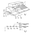
- the electronic display field 3 the output device 5 for a receipt 6, the viewing window 7 for the journal strip, a printing table 9 is provided for inserting receipts 10 of different sizes into the printer.
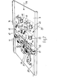
- Fig. 2 shows the printing table 9 without the device of the printer arranged above it.
- the transport roller pairs 11 indicate the transport device for the line-by-line feed for multi-line printing of the documents and for ejecting the documents after the printing has been carried out.
- the stationary printing table 9 is delimited by two lateral and a rear stop 13 and 14 or 15.
- the first side stop 13 can be lowered and serves as a stop for small documents, hereinafter referred to as labels.
- the second side stop 14 is fixed and serves as a stop for larger forms hereinafter referred to as documents.
- a rear stop 15 serves both for the labels and for the receipts to be printed, as a limitation when feeding and for positioning.
- the first lateral stop 13 is mounted on an only indicated pivot axis 17 and projects, held by a spring (not shown) in the position shown in FIG. 2, with its free end 13 a from below through a slot 19 in the printing table 9 and leads when loading its free end 13 a with the ramp slope 21 from a short clockwise rotation until the upper edge 13 b of the ramp slope lies in the plane of the printing table 9.
- a spring not shown
- the run-up slope 21 lies at an acute angle to the surface of the printing table 9, and the spring-loaded mounting of the first lateral stop 13 is designed such that by inserting a document in the direction of the arrow 25 (FIGS. 1 and 2) on the printing table 9 into the printing position by running onto the ramp slope 21, the first lateral stop 13 is lowered.
- the rear stop 15 (Fig. 2) is also spring-loaded on a fixed axis 27 and projects with two bends 29 and 30 through slots in the space above the printing table 9, so that in the direction of arrows 25 or 26 (Fig. 1 and 2) introduced documents come to a stop at the bends 29 and 30.
- the bend 29 of the rear stop 15 has a run-on slope 31 (FIG. 2) on the side, which in the same way as the run-up slope 21 of the first lateral stop 13 includes an acute angle to the printing table 9.
- a large document for example, occupying the entire length of the printing table 9, if it is inserted into the printing position 9 in the direction of arrow 33 (FIGS. 1 and 2) on the printing table 9, by running onto the ramp 31, the rear stop 15 into the Lower the level of the printing table 9.
- the first side stop 13 is assigned two label sensors 35 and 36 on the insertion side, which are at an angle of approximately 45 to the side stop 13 and, like the first side stop, project through a slot 38 and 39 in the printing table 9.
- the first label sensor 35 which is arranged close to the run-up slope 21 of the first lateral stop 13, serves to signal the end of the document when printing in multiple lines, and the second label sensor 36 responds when a label or a document is in a sufficiently precise position in front of the rear Stop 15 is brought.
- a document sensor 41 is arranged in a position corresponding to the label sensor 35, which responds when a document has assumed the desired position in front of the second side stop 14.
- the document sensor 41 which projects through a slot 42 in the printing table 9, and the first label sensor 35 are mounted on an axis 43 fixed to the frame and are each held in the position shown in FIG. 2 by a spring (not shown) when there is no document or Label is inserted.
- All of the label or receipt sensors 35, 36 and 41 are each assigned a microswitch 45, 46, which are actuated when the label sensor or the receipt sensor is lowered when a label or receipt is inserted. As shown schematically in FIG.
- the printer by responding to the two label sensors 35 and 36, the printer is closed by closing the contact 35a of the second microswitch 45 and the contact 36a of the microswitch (not shown) of the second label sensor 36 by responding to a first control circuit 48 signals that a label is properly inserted and only the reduced pressure in the print line 47 (FIG. 2) is to take place.
- the assigned second label sensor 36 and the document sensor 41 are also lowered by addressing Their microswitches closed the contacts 35a, 36a and 13d, the contact 41a of the microswitch 46 on the receipt sensor 41 switched over and signaled to the printer by responding to a second control circuit 49 that a larger receipt had been inserted and printing was to take place over the entire print line 47.
- the rear stop 15 is lowered and the document is closed by one line spacing in the direction of the arrow by closing the transport roller pairs 11 (FIG. 2) 26 transported. If the last available line is printed in the case of a multi-line print on a document, the first label sensor 35 released by the document end signals the end of the form and triggers the further drive of the transport rollers 11 and thereby causes the document to be ejected.
- the rear stop 15 can be lowered by laterally inserting the forms in the direction of arrow 25 if the form also detects the bevel 31.
Abstract
Description
Die Erfindung betrifft eine Einrichtung zum genauen Einführen in die Druckstellung und zum Bedrucken von unterschiedlich großen Belegen in elektronischen Registrierkassen oder dergleichen Buchungsmaschinen, in der Etiketten als auch größere Belege auf einem horizontalen mit absenkbaren Anschlägen versehenen Drucktisch bedruckbar sind.The invention relates to a device for precise insertion into the printing position and for printing receipts of different sizes in electronic cash registers or similar booking machines, in which labels as well as larger receipts can be printed on a horizontal printing table provided with lowerable stops.
In der DE-PS 25 56 331 ist bereits eine Einrichtung zum genauen Einlegen von unterschiedlich großen Belegen in die Druckstellung in Registrierkassen oder dergleichen Buchungsmaschinen beschrieben. Bei dieser bekannten Einrichtung ist beim Bedrucken unterschiedlich großer Belege jedoch die Abmessung des Druckfeldes bei den zu bedruckenden Aufzeichnungsträgern von der Größe desselben nicht beeinflußbar.DE-PS 25 56 331 has already described a device for the precise insertion of documents of different sizes into the printing position in cash registers or similar booking machines. In this known device, however, when printing documents of different sizes, the size of the printing field on the recording media to be printed cannot be influenced.
Der Erfindung liegt die Aufgabe zugrunde, die Länge des Druckfeldes abhängig von der Größe des Aufzeichnungsträgers zu gestalten, so daß z. B. durch wahlweises Einlegen von Etiketten oder größeren Belegen automatisch ohne manuellen Eingriff der Bedienungsperson ein Druck mit einem Druckfeld unterschiedlicher Länge ausgelöst werden kannn.The invention has for its object to make the length of the print field depending on the size of the record carrier, so that, for. B. can be triggered automatically by manual insertion of labels or larger receipts without manual intervention by the operator, a pressure with a printing field of different lengths.
Die gestellte Aufgabe wird durch die im Kennzeichen des Patentanspruchs 1 angegebenen Merkmale gelöst. Weitere Ausbildungen des Erfindungsgegenstandes sind in den Unteransprüchen aufgeführt.The object is achieved by the features specified in the characterizing part of
Ein Ausführungsbeispiel der Erfindung wird nun an Hand der Zeichnungen im einzelnen beschrieben. Es zeigen:
- Fig. 1 eine elektronsiche Registrierkasse
- Fig. 2 eine perspektivische Ansicht des Drucktisches mit Darstellung der unter dem Drucktisch angeordneten Bauelemente und
- Fig. 3 ein Blockschaltbild für die Druckwerksteuerung.
- Fig. 1 is an electronic cash register
- Fig. 2 is a perspective view of the printing table showing the components arranged under the printing table and
- Fig. 3 is a block diagram for the printing unit control.
An der in Fig. 1 dargestellten elektronischen Registrierkasse mit ihrem Tastenfeld 1, dem elektronischen Anzeigefeld 3, der Ausgabeeinrichtung 5 für einen Kassenbon 6, dem Sichtfenster 7 für den Journalstreifen ist ein Drucktisch 9 zum Einführen von Belegen 10 unterschiedlicher Größe in den Drucker vorgesehen.At the electronic cash register shown in FIG. 1 with its
Fig. 2 zeigt den Drucktisch 9 ohne die über ihm angeordnete Vorrichtung des Druckers. Mit den Transportwalzenpaaren 11 ist die Transporteinrichtung für den zeilenweisen Vorschub zum mehrzeiligen Bedrucken der Belege und zum Auswerfen der Belege nach Durchführung des Druckes angedeutet. Der stationäre Drucktisch 9 wird durch zwei seitliche und einen hinteren Anschlag 13 und 14 bzw. 15 begrenzt.Fig. 2 shows the printing table 9 without the device of the printer arranged above it. The
Der erste seitliche Anschlag 13 ist absenkbar und dient als Anschlag für kleine Belege, im folgenden beispielsweise als Etiketten bezeichnet. Der zweite seitliche Anschlag 14 ist fest und dient als Anschlag für größere Formulare im folgenden kurz als Belege bezeichnet. Sowohl für die Etiketten, als auch für die zu bedruckenden Belege dient ein hinterer Anschlag 15 als Begrenzung beim Einzug und für die Positionierung.The
Der erste seitliche Anschlag 13 ist auf einer nur angedeuteten Schwenkachse 17 gelagert und ragt, durch eine Feder (nicht dargestellt) in der in Fig. 2 dargestellten Lage gehalten, mit seinem freien Ende 13 a von unten durch einen Schlitz 19 im Drucktisch 9 und führt bei Belastung seines freien Endes 13 a mit der Auflaufschräge 21 eine kurze Schwenkung im Uhrzeigerdrehsinn aus, bis die Oberkante 13 b der Auflaufschräge in der Ebene des Drucktisches 9 liegt. Bei Absenkung des ersten seitlichen Anschlags 13 betätigt dieser einen ersten Mikroschalter 23. Die Auflaufschräge 21 liegt in einem spitzen Winkel zur Oberfläche des Drucktisches 9, und die ferderbelastete Lagerung des ersten seitlichen Anschlags 13 ist so gestaltet, daß durch Einführen eines Belegs in Richtung des Pfeiles 25 (Fig. 1 und 2) auf den Drucktisch 9 in die Druckstellung durch Auflaufen auf die Auflaufschräge 21 der erste seitliche Anschlag 13 abgesenkt wird.The first
Der hintere Anschlag 15 (Fig. 2) ist auf einer gestellfesten Achse 27 ebenfalls federbelastet gelagert und ragt mit zwei Abwinklungen 29 und 30 durch Schlitze in den Raum über dem Drucktisch 9, so daß in Richtung der Pfeile 25 oder 26 (Fig. 1 und 2) eingeführte Belege an den Abwinklungen 29 und 30 zum Stehen kommen. Die Abwinklung 29 des hinteren Anschlags 15 weist seitlich eine Auflaufschräge 31 (Fig. 2) auf, die in gleicher Weise wie die Auflaufschräge 21 des ersten seitlichen Anschlags 13 einen spitzen Winkel zum Drucktisch 9 einschließt. Ein beispielsweise die ganze Länge des Drucktisches 9 einnehmender großer Beleg kann, wenn er in Richtung des Pfeiles 33 (Fig. 1 und 2) auf dem Drucktisch 9 in die Druckstellung eingeführt wird, durch Auflaufen auf die Auflaufschräge 31 den hinteren Anschlag 15 bis in die Ebene des Drucktisches 9 absenken.The rear stop 15 (Fig. 2) is also spring-loaded on a
Dem ersten seitlichen Anschlag 13 sind einführseitig zwei Etikettfühler 35 und 36 zugeordnet, die in einem Winkel von etwa 45 zum seitlichen Anschlag 13 stehen und wie der erste seitliche Anschlag durch einen Schlitz 38 bzw. 39 im Drucktisch 9 ragen. Der erste Etikettfühler 35, der dicht neben der Auflaufschräge 21 des ersten seitlichen Anschlags 13 angeordnet ist, dient zur Signalisierung des Belegendes bei mehrzeiligem Druck, und der zweite Etikettfühler 36 spricht an, wenn ein Etikett oder ein Beleg in einer ausreichend genaue Lage vor den hinteren Anschlag 15 gebracht ist.The
Vor dem zweiten seitlichen Anschlag 14 ist ein Belegfühler 41 in einer entsprechenden Lage wie der Etikettfühler 35 angeordnet, der anspricht, wenn ein Beleg die gewünschte Lage vor dem zweiten seitlichen Anschlag 14 eingenommen hat. Der Belegfühler 41, der durch einen Schlitz 42 des Drucktisches 9 ragt, und der erste Etikettfühler 35 sind auf einer gestellfesten Achse 43 gelagert und werden durch je eine Feder (nicht dargestellt) in der in Fig. 2 dargestellten Lage gehalten, wenn kein Beleg bzw. Etikett eingeführt ist. Allen Etikett- bzw. Belegfühlern 35, 36 bzw. 41 ist jeweils ein Mikroschalter 45, 46 zugeordnet, die beim Absenken der Etikettfühler bzw. des Belegfühlers beim Einlegen eines Etiketts oder Belegs betätigt werden. Wie in Fig. 3 schematisch dargestellt ist, wird durch Ansprechen der beiden Etikettfühler 35 und 36 dem Drucker durch Schließen des Kontaktes 35a des zweiten Mikroschalters 45 und des Kontaktes 36a des nicht dargestellten Mikroschalters des zweiten Etikettfühlers 36 durch Ansprechen einer ersten Steuerschaltung 48 signalisiert, daß ein Etikett ordnungsgemäß eingelegt ist und nur der reduzierte Druck in der Druckzeile 47 (Fig. 2) erfolgen soll.In front of the
Werden beim Einlegen eines Aufzeichnungsträgers in Richtung der Pfeile 25 oder 26 der erste seitliche Anschlag 13 mit seinem ersten Etikettfühler und beim Ausrichten am zweiten seitlichen Anschlag 14 und am hinteren Anschlag 15 auch der zugeordnete zweite Etikettfühler 36 und der Belegfühler 41 abgesenkt, so werden durch Ansprechen ihrer Mikroschalter die Kontakte 35a, 36a und 13d geschlossen, der Kontakt 41a des Mikroschalters 46 am Belegfühler 41 umgeschaltet und durch Ansprechen einer zweiten Steuerschaltung 49 dem Drucker signalisiert, daß ein größerer Beleg eingelegt wurde und ein Druck über die gesamte Druckzeile 47 erfolgen soll.If when inserting a record carrier in the direction of
Bei einem mehrzeiligen Druck auf einen Beleg wird nach dem Einführen des Belegs bis an den hinteren Anschlag 15 und dem Abdruck der ersten Zeile der hintere Anschlag 15 abgesenkt und der Beleg durch Schließen der Transportrollenpaare 11 (Fig. 2) um einen Zeilenabstand in Richtung des Pfeiles 26 transportiert. Wenn bei einem mehrzeiligen Druck auf einen Beleg die letzte verfügbare Zeile bedruckt ist, signalisiert der durch das Belegende freigegebene erste Etikettfühler 35 das Formularende und löst den weiteren Antrieb der Transportrollen 11 aus und veranlaßt dadurch das Auswerfen des Belegs.In the case of a multi-line print on a document, after inserting the document up to the
Um den Drucker vielseitig verwenden zu können und auch Formulare mit unterschiedlichen größeren Abmessungen bedrucken zu können, läßt sich der hintere Anschlag 15 durch seitliches Einführen der Formulare in Richtung des Pfeiles 25 absenken, wenn das Formular dabei auch die Auflaufschräge 31 erfaßt.In order to be able to use the printer in a versatile manner and also to be able to print forms with different larger dimensions, the
Wird hierbei das große Formular so eingelegt, daß dabei sowohl die beiden Etikettfühler 35 und 36 als auch der erste seitliche Anschlag 13 und der Belegfühler 41 abgesenkt und dadurch die zugeordneten Mikroschalter betätigt werden, erfolgt ein einzeiliger oder mehrzeiliger Abdruck in der gesamten Druckzeile.If the large form is inserted in such a way that both the
Claims (6)
Priority Applications (1)
| Application Number | Priority Date | Filing Date | Title |
|---|---|---|---|
| AT85100367T ATE35651T1 (en) | 1984-02-01 | 1985-01-16 | DEVICE FOR PRECISE INSERTION INTO THE PRINTING POSITION AND FOR PRINTING RECEIPTS OF DIFFERENT SIZES IN ELECTRONIC CASH REGISTERS OR THE LIKE. |
Applications Claiming Priority (2)
| Application Number | Priority Date | Filing Date | Title |
|---|---|---|---|
| DE3403396A DE3403396C1 (en) | 1984-02-01 | 1984-02-01 | Device for precise introduction into the printing position and for printing documents of different sizes in electronic cash registers or the like |
| DE3403396 | 1984-02-01 |
Publications (3)
| Publication Number | Publication Date |
|---|---|
| EP0150761A2 true EP0150761A2 (en) | 1985-08-07 |
| EP0150761A3 EP0150761A3 (en) | 1986-07-30 |
| EP0150761B1 EP0150761B1 (en) | 1988-07-13 |
Family
ID=6226434
Family Applications (1)
| Application Number | Title | Priority Date | Filing Date |
|---|---|---|---|
| EP85100367A Expired EP0150761B1 (en) | 1984-02-01 | 1985-01-16 | Device for the accurate insertion towards the print position and for printing on forms of different sizes in an electronic cast register or the like |
Country Status (3)
| Country | Link |
|---|---|
| EP (1) | EP0150761B1 (en) |
| AT (1) | ATE35651T1 (en) |
| DE (1) | DE3403396C1 (en) |
Cited By (3)
| Publication number | Priority date | Publication date | Assignee | Title |
|---|---|---|---|---|
| WO1991013765A1 (en) * | 1990-03-16 | 1991-09-19 | Siemens Nixdorf Informationssysteme Aktiengesellschaft | Printer with a printer housing divided in the plane of the print carrier |
| EP0949083A1 (en) * | 1996-11-08 | 1999-10-13 | Star Micronics Co., Ltd. | Printer |
| EP3013648B1 (en) | 2013-06-28 | 2018-03-28 | Tönjes, Piet | Method for producing an identifier and identifier |
Citations (1)
| Publication number | Priority date | Publication date | Assignee | Title |
|---|---|---|---|---|
| DE2556331A1 (en) * | 1975-12-13 | 1977-06-23 | Anker Werke Ag | Card positioning appts. for office machine - has movable table with adjustable lays for different size of card |
-
1984
- 1984-02-01 DE DE3403396A patent/DE3403396C1/en not_active Expired
-
1985
- 1985-01-16 EP EP85100367A patent/EP0150761B1/en not_active Expired
- 1985-01-16 AT AT85100367T patent/ATE35651T1/en not_active IP Right Cessation
Patent Citations (1)
| Publication number | Priority date | Publication date | Assignee | Title |
|---|---|---|---|---|
| DE2556331A1 (en) * | 1975-12-13 | 1977-06-23 | Anker Werke Ag | Card positioning appts. for office machine - has movable table with adjustable lays for different size of card |
Cited By (6)
| Publication number | Priority date | Publication date | Assignee | Title |
|---|---|---|---|---|
| WO1991013765A1 (en) * | 1990-03-16 | 1991-09-19 | Siemens Nixdorf Informationssysteme Aktiengesellschaft | Printer with a printer housing divided in the plane of the print carrier |
| US5320437A (en) * | 1990-03-16 | 1994-06-14 | Siemens Nixdorf Informationssysteme Aktiengesellschaft | Printer with a printer housing divided in the plane of the print carrier |
| EP0949083A1 (en) * | 1996-11-08 | 1999-10-13 | Star Micronics Co., Ltd. | Printer |
| EP0949083A4 (en) * | 1996-11-08 | 2000-05-03 | Star Mfg Co | Printer |
| US6126340A (en) * | 1996-11-08 | 2000-10-03 | Star Micronics Co., Ltd. | Printer |
| EP3013648B1 (en) | 2013-06-28 | 2018-03-28 | Tönjes, Piet | Method for producing an identifier and identifier |
Also Published As
| Publication number | Publication date |
|---|---|
| ATE35651T1 (en) | 1988-07-15 |
| DE3403396C1 (en) | 1984-12-20 |
| EP0150761A3 (en) | 1986-07-30 |
| EP0150761B1 (en) | 1988-07-13 |
Similar Documents
| Publication | Publication Date | Title |
|---|---|---|
| EP0052408A2 (en) | Printing mechanism with a recording element and means for the rotation of a record carrier | |
| DE2618089A1 (en) | DEVICE FOR INSERTING A SINGLE SHEET-SHAPED COPY CARRIER INTO THE COPY CARRIAGE CONVEYOR OF A COPY DEVICE | |
| DE3226510C2 (en) | Universal paper transport device for single sheets and continuous paper in line printing devices | |
| DE3119025A1 (en) | THERMAL PRINTER | |
| DE3818167C2 (en) | ||
| DE4023499A1 (en) | CONTINUOUS PAPER SELF-LOADING MECHANISM FOR THERMAL PRINTER | |
| DE3034517C1 (en) | Device for transporting a data carrier in a data recognition device | |
| DE2717758B2 (en) | Device for guiding paper in printing equipment, in particular in data and telex typing machines | |
| DE2749976A1 (en) | RECORDING DEVICE | |
| EP0150761B1 (en) | Device for the accurate insertion towards the print position and for printing on forms of different sizes in an electronic cast register or the like | |
| DE3319115C2 (en) | ||
| DE1549817A1 (en) | Manually operated receipt card reader | |
| DE2738855A1 (en) | DEVICE FOR PAPER GUIDING IN PRINTING DEVICES, IN PARTICULAR IN DATA AND TELEPHONE MACHINES | |
| DE2946033A1 (en) | PAPER FEEDING DEVICE FOR PRINTING DEVICES WITH SEVERAL, AXIAL ARRANGEMENTS OF PAPER GUIDE TUBES | |
| EP0035178A1 (en) | Device for printers for depositing sheet-like record carriers | |
| DE1262645B (en) | Raster printer | |
| DE4344493A1 (en) | Internal drum printer with paper feed device | |
| EP0019079A1 (en) | Document positioning device | |
| DE2307893B2 (en) | ||
| DE3421406C1 (en) | Ribbon cassette for typewriters or similar machines | |
| DE2847917A1 (en) | TYPEWRITER, PRINTER, ETC. | |
| EP0330847B1 (en) | Printing device, in particular a transport ticket printing device | |
| DE60315306T2 (en) | Alignment of recording material in a printing device | |
| DE3031992C2 (en) | ||
| DE2742947A1 (en) | DEVICE FOR PAPER GUIDE IN PRINTING EQUIPMENT, ESPECIALLY IN DATA AND TELETYPE MACHINES |
Legal Events
| Date | Code | Title | Description |
|---|---|---|---|
| PUAI | Public reference made under article 153(3) epc to a published international application that has entered the european phase |
Free format text: ORIGINAL CODE: 0009012 |
|
| AK | Designated contracting states |
Designated state(s): AT CH FR GB IT LI NL |
|
| PUAL | Search report despatched |
Free format text: ORIGINAL CODE: 0009013 |
|
| AK | Designated contracting states |
Kind code of ref document: A3 Designated state(s): AT CH FR GB IT LI NL |
|
| EL | Fr: translation of claims filed | ||
| TCNL | Nl: translation of patent claims filed | ||
| 17P | Request for examination filed |
Effective date: 19860827 |
|
| 17Q | First examination report despatched |
Effective date: 19870901 |
|
| ITF | It: translation for a ep patent filed |
Owner name: DE DOMINICIS & MAYER S.R.L. |
|
| GRAA | (expected) grant |
Free format text: ORIGINAL CODE: 0009210 |
|
| AK | Designated contracting states |
Kind code of ref document: B1 Designated state(s): AT CH FR GB IT LI NL |
|
| REF | Corresponds to: |
Ref document number: 35651 Country of ref document: AT Date of ref document: 19880715 Kind code of ref document: T |
|
| ET | Fr: translation filed | ||
| GBT | Gb: translation of ep patent filed (gb section 77(6)(a)/1977) | ||
| PLBE | No opposition filed within time limit |
Free format text: ORIGINAL CODE: 0009261 |
|
| STAA | Information on the status of an ep patent application or granted ep patent |
Free format text: STATUS: NO OPPOSITION FILED WITHIN TIME LIMIT |
|
| 26N | No opposition filed | ||
| ITTA | It: last paid annual fee | ||
| PGFP | Annual fee paid to national office [announced via postgrant information from national office to epo] |
Ref country code: FR Payment date: 19931215 Year of fee payment: 10 |
|
| PGFP | Annual fee paid to national office [announced via postgrant information from national office to epo] |
Ref country code: AT Payment date: 19931220 Year of fee payment: 10 |
|
| PGFP | Annual fee paid to national office [announced via postgrant information from national office to epo] |
Ref country code: GB Payment date: 19940106 Year of fee payment: 10 |
|
| PGFP | Annual fee paid to national office [announced via postgrant information from national office to epo] |
Ref country code: NL Payment date: 19940131 Year of fee payment: 10 |
|
| PGFP | Annual fee paid to national office [announced via postgrant information from national office to epo] |
Ref country code: CH Payment date: 19940422 Year of fee payment: 10 |
|
| PG25 | Lapsed in a contracting state [announced via postgrant information from national office to epo] |
Ref country code: GB Effective date: 19950116 Ref country code: AT Effective date: 19950116 |
|
| PG25 | Lapsed in a contracting state [announced via postgrant information from national office to epo] |
Ref country code: CH Effective date: 19950131 Ref country code: LI Effective date: 19950131 |
|
| PG25 | Lapsed in a contracting state [announced via postgrant information from national office to epo] |
Ref country code: NL Effective date: 19950801 |
|
| GBPC | Gb: european patent ceased through non-payment of renewal fee |
Effective date: 19950116 |
|
| PG25 | Lapsed in a contracting state [announced via postgrant information from national office to epo] |
Ref country code: FR Effective date: 19950929 |
|
| REG | Reference to a national code |
Ref country code: CH Ref legal event code: PL |
|
| NLV4 | Nl: lapsed or anulled due to non-payment of the annual fee |
Effective date: 19950801 |
|
| REG | Reference to a national code |
Ref country code: FR Ref legal event code: ST |