EP0150720B1 - Fritiergerät mit indirekter elektrischer Beheizung - Google Patents
Fritiergerät mit indirekter elektrischer Beheizung Download PDFInfo
- Publication number
- EP0150720B1 EP0150720B1 EP19850100124 EP85100124A EP0150720B1 EP 0150720 B1 EP0150720 B1 EP 0150720B1 EP 19850100124 EP19850100124 EP 19850100124 EP 85100124 A EP85100124 A EP 85100124A EP 0150720 B1 EP0150720 B1 EP 0150720B1
- Authority
- EP
- European Patent Office
- Prior art keywords
- container
- vessel
- oil
- fryer
- shaft
- Prior art date
- Legal status (The legal status is an assumption and is not a legal conclusion. Google has not performed a legal analysis and makes no representation as to the accuracy of the status listed.)
- Expired
Links
- 238000010438 heat treatment Methods 0.000 title claims description 25
- 238000004891 communication Methods 0.000 claims description 4
- 229910001220 stainless steel Inorganic materials 0.000 claims description 4
- 239000010935 stainless steel Substances 0.000 claims description 4
- 230000002093 peripheral effect Effects 0.000 claims description 3
- 241000711981 Sais Species 0.000 claims 1
- 238000004140 cleaning Methods 0.000 description 7
- 230000008901 benefit Effects 0.000 description 5
- 238000006731 degradation reaction Methods 0.000 description 5
- 230000015556 catabolic process Effects 0.000 description 4
- 238000010276 construction Methods 0.000 description 4
- 238000012423 maintenance Methods 0.000 description 4
- 230000015572 biosynthetic process Effects 0.000 description 2
- 238000013461 design Methods 0.000 description 2
- 230000000694 effects Effects 0.000 description 2
- 238000002474 experimental method Methods 0.000 description 2
- 238000000605 extraction Methods 0.000 description 2
- 235000013305 food Nutrition 0.000 description 2
- 238000007254 oxidation reaction Methods 0.000 description 2
- 238000005086 pumping Methods 0.000 description 2
- 230000009467 reduction Effects 0.000 description 2
- 238000007789 sealing Methods 0.000 description 2
- 238000013019 agitation Methods 0.000 description 1
- 230000004323 axial length Effects 0.000 description 1
- 230000005540 biological transmission Effects 0.000 description 1
- 230000008878 coupling Effects 0.000 description 1
- 238000010168 coupling process Methods 0.000 description 1
- 238000005859 coupling reaction Methods 0.000 description 1
- 238000005485 electric heating Methods 0.000 description 1
- 239000006260 foam Substances 0.000 description 1
- 239000000383 hazardous chemical Substances 0.000 description 1
- 231100000206 health hazard Toxicity 0.000 description 1
- 238000007689 inspection Methods 0.000 description 1
- 238000000034 method Methods 0.000 description 1
- 230000000737 periodic effect Effects 0.000 description 1
- 230000008569 process Effects 0.000 description 1
- 238000009877 rendering Methods 0.000 description 1
- 230000008439 repair process Effects 0.000 description 1
- 238000005476 soldering Methods 0.000 description 1
- 239000000126 substance Substances 0.000 description 1
- 238000003466 welding Methods 0.000 description 1
Images

Classifications
-
- A—HUMAN NECESSITIES
- A47—FURNITURE; DOMESTIC ARTICLES OR APPLIANCES; COFFEE MILLS; SPICE MILLS; SUCTION CLEANERS IN GENERAL
- A47J—KITCHEN EQUIPMENT; COFFEE MILLS; SPICE MILLS; APPARATUS FOR MAKING BEVERAGES
- A47J37/00—Baking; Roasting; Grilling; Frying
- A47J37/12—Deep fat fryers, e.g. for frying fish or chips
- A47J37/1233—Deep fat fryers, e.g. for frying fish or chips the frying liquid being heated outside the frying vessel, e.g. by pumping it through a heat exchanger
Definitions
- the present invention relates to a fryer, particularly for use in a community kitchen, provided with electric heater means for indirect heating of the frying oil or fat.
- An electric fryer as disclosed in GB-A-1 111 090 comprises a stainless steel vessel a rear portion of which contains at least one armoured resistance heater hingedly mounted or guided in such a manner that in operation its active heater portion is completely immersed in the oil.
- a stainless steel vessel a rear portion of which contains at least one armoured resistance heater hingedly mounted or guided in such a manner that in operation its active heater portion is completely immersed in the oil.
- one achieves direct heating of the oil but because of the low heat transmission coefficient between the heater surface and the oil there occurs a considerable temperature difference of as much as 100°C or above between the heater surface and the oil.
- the oil in contact with the heater surface is subjected to a degradation process which, in addition to rendering the cleaning of. the resistance heater difficult, converts some of the oil to substances constituting particular health hazards.
- a first solution to this problem consists in increasing the heat-transmitting surface area of the resistance heater(s) in proportion to its or their capacity so as to reduce the above noted temperature difference to acceptable values.
- This solution requires the employ of resistance heaters having excessive dimensions and intricate shapes, thus complicating the design, the use and, above all, the periodic cleaning of the fryer.
- the heating container which is usually disposed with its axis vertical, is required to have a considerable axial length and thus occupies a considerable vertical space below the bottom of the vessel.
- the container has to be provided with an element mounted therein for agitating and circulating the oil and driven by an externally mounted motor.
- the motor is preferably mounted above the level of the oil in the frying vessel, i.e. at an uncomfortable and not readily accessible location.
- the fryer according to the invention thus comprises a stainless steel vessel and a container located adjacent said vessel in communication therewith, said container being provided with electric heater means secured to its outer wall surface and with means for forcedly circulating the frying oil between said container and said vessel, said fryer being characterized in that said container is located adjacent the front side of the fryer and communicates with an expansion zone of said vessel, and in that said means for forcedly circulating the oil comprises a vaned shaft mounted coaxially in said container and having its lower end telescopingly coupled to an electric motor for driving said shaft, the upper end of said shaft being rotatably but non-slidably connected to a closure plug of said container, the engagement length of said lower end being smaller than the engagement length of said plug in said container.
- This arrangement for heating and forcedly circulating the oil is capable of producing a considerable turbulence in the heat exchange zone, with the resultant reduction of the temperature difference between the heating surface and the frying oil, so as to avoid the degradation of the oil.
- This advantage is the more noticeable, the greater the number of vanes on said shaft and the closer the vanes extend towards the container wall.
- to obtain the maximum advantage would require an extremely accurate and thus costly construction of the rotor, i.e. of the vaned shaft.
- a great number of vanes would induce the entire mass of the oil to rotate, whereby the pumping effect would be reduced, resulting in a reduced circulation and excessive agitation of the oil, with the consequent oxydation thereof due to the formation of air bubbles.
- a further object of the invention is thus the provision of a rotor of very simple construction and designed to be mounted and serviced in a simple manner while being capable of producing maximum turbulence in the flow of the frying oil preferably or solely in the zone immediately adjacent the wall of the heating assembly.
- a rotor having a central shaft carrying a plurality of radial vanes and characterized in that a plurality of rods extending substantially paral- lely to said shaft is secured to said vanes at a peripheral zone thereof proximate the heating wall.
- a fryer shown in Fig. 1 has a housing 5 containing a stainless steel vessel 6 for containing an oil bath 7 and formed with an expansion zone 8 adjacent the front side 9 of the fryer.
- the term "expansion zone 8" denotes a part of the vessel destined to contain the foam formed during the frying process and extending from the level of oil bath 7 to an overflow level.
- the lower portion of vessel 6 is provided with a discharge conduit 10 and filter 11 disposed on the inclined bottom of the vessel converging towards the opening of discharge conduit 10.
- Inserted into vessel 6 is a basket 12 for containing the food to be fried.
- a container 13 is mounted in the fryer adjacent the front side thereof, with its lower end in communication with discharge conduit 10 and its upper end connected to vessel 6 through a conduit 14.
- Container 13 is provided with electric resistance heaters 15 wound on its outer surface and secured thereto by welding or soldering, and contains a means for forcedly circulating the oil between container 13 and vessel 6.
- the forced circulation means comprises a vaned shaft 16 mounted coaxially in container 13 and having its lower end telescopingly engaged with an electric motor 17, while its upper end is rotatably but non-slidably connected to a closure plug 18 of container 13.
- the length Y of the telescoping engagement of the lower end is smaller than the engagement length X of plug 18 in container 13 so as to ensure the safety of the operator on disassembly of the fryer for cleaning and maintenance purposes.
- the rotor including shaft 16 may thus be extracted from container 13 by lifting plug 18, the driving connection to motor 17 being released prior to the complete extraction of plug 18 from container 13 so as to exclude any danger to the operator.
- Motor 17 is disposed outside container 13.
- the shaft of motor 17 has to be provided with conventional sealing means for avoiding or at least controlling leakage of the heated oil.
- a normally closed discharge valve 19 Inserted in discharge conduit 10 downstream of container 13 is a normally closed discharge valve 19 permitting the oil to be discharged from vessel 6 and container 13 if so required for maintenance or repair of the fryer.
- the fryer according to the invention offers the following advantages with regard to efficiency and facility of operation:
- the indirect heating of the oil in combination with the forced circulation ensures a uniform temperature of the oil bath and reduces the danger of degradation of the oil, with the resultant advantages as regards the quality of the prepared foods.
- the arrangement of container 13 with the associated means for heating and forcedly circulating the oil at a forward location of the fryer and in outlet communication with the expansion zone, and the location of the motor below the container ensure optimum accessibility of the container and its connecting passages for cleaning and maintenance purposes.
- the telescope-type coupling of the elements of the forced circulation means permits the associated parts to be readily disassembled without any danger to the operator.
- the different lengths of the upper and lower mountings of shaft 16 are effective to ensure uncoupling of shaft 16 from motor 17 prior to the extraction of the rotor from container 13.
- Fig. 2 shows an alternative embodiment of the fryer according to the invention.
- This embodiment differs from the one shown in Fig. 1 mainly in that discharge conduit 10 is extended downwards in the front portion of the fryer.
- oil heating container 13 is no longer directly inserted in discharge conduit 10, but connected thereto via a short inlet conduit 20.
- This embodiment further permits a receptacle 21 to be placed into the lower portion of housing 5 for collecting the oil discharged by opening valve 19.
- the Fig. 2 embodiment has the slight disadvantage that inlet conduit 20 is not as readily accessible for cleaning and inspection.
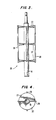
- a rotor 25 is formed by shaft 16 having a plurality of radial vanes welded thereto.
- Vanes 27 are preferably of semicircular shape and arranged at inclined positions with respect to the axis of shaft 16. Otherwise vanes 27 are arranged in pairs opposite one another and at equal spacings along the length of shaft 16.
- a plurality of rods 28 is welded to the free ends of vanes 27 in spaced relation and substantially parallel to the axis of shaft 16. There are preferably four rods 28 located at diametrally opposite positions with respect to the axis of shaft 16.
- rods 28 may be directly connected to shaft 16 through radial links.
- the rods have to be mounted for rotation together with the remainder of the rotor and should be disposed in the peripheral zone of the vanes as close as possible to the heating wall.
- Rotor 25 is obviously of very simple construction and desinged for simple and efficient employ in an oil heating and circulating arrangement of the type described.
- the rotor according to the invention exerts an efficient pumping effect for the circulation of the oil between the heating arrangement and the vessel of the fryer.
- the rods 28 disposed peripherally of vanes 27 are effective to induce a violent turbulence in the oil flow adjacent the heat exchange wall of the heating contrainer, while the overall turbulence of the oil flow remains relatively low.
- This arrangement minimizes the danger of oxydation of the oil due to the formation of air bubbles.
- the temperature difference AT between the heating wall and the oil is reduced to very low values in the order of 20 to 30°C, so that the degradation of the oil, and thus the consumption thereof, is minimized.
Landscapes
- Engineering & Computer Science (AREA)
- Food Science & Technology (AREA)
- Frying-Pans Or Fryers (AREA)
Claims (8)
Priority Applications (1)
| Application Number | Priority Date | Filing Date | Title |
|---|---|---|---|
| AT85100124T ATE33924T1 (de) | 1984-01-20 | 1985-01-08 | Fritiergeraet mit indirekter elektrischer beheizung. |
Applications Claiming Priority (4)
| Application Number | Priority Date | Filing Date | Title |
|---|---|---|---|
| ITPN1984U34003U IT8434003U1 (it) | 1984-01-20 | 1984-01-20 | Friggitrice con dispositivo di riscaldamento elettrico indiretto |
| IT3400384U | 1984-01-20 | ||
| ITPN1984U34061U IT8434061U1 (it) | 1984-10-10 | 1984-10-10 | Girante per dispositivo di riscaldamento dell'olio nelle friggitrici |
| IT3406184U | 1984-10-10 |
Publications (2)
| Publication Number | Publication Date |
|---|---|
| EP0150720A1 EP0150720A1 (de) | 1985-08-07 |
| EP0150720B1 true EP0150720B1 (de) | 1988-05-04 |
Family
ID=26328982
Family Applications (1)
| Application Number | Title | Priority Date | Filing Date |
|---|---|---|---|
| EP19850100124 Expired EP0150720B1 (de) | 1984-01-20 | 1985-01-08 | Fritiergerät mit indirekter elektrischer Beheizung |
Country Status (3)
| Country | Link |
|---|---|
| EP (1) | EP0150720B1 (de) |
| DE (1) | DE3562447D1 (de) |
| ES (1) | ES539211A0 (de) |
Families Citing this family (2)
| Publication number | Priority date | Publication date | Assignee | Title |
|---|---|---|---|---|
| FR2688994A1 (fr) * | 1992-03-31 | 1993-10-01 | Rousseau Jean Pierre | Friteuse. |
| CN112978100B (zh) * | 2021-02-25 | 2023-03-28 | 德州金奈尔新材料科技有限公司 | 一种新材料加工用的加热装置 |
Family Cites Families (3)
| Publication number | Priority date | Publication date | Assignee | Title |
|---|---|---|---|---|
| US2243661A (en) * | 1940-07-30 | 1941-05-27 | Ken Vic Inc | Deep fat food fryer |
| US3977390A (en) * | 1974-11-07 | 1976-08-31 | Burger King Corporation | Heated oil cooking apparatus for comestibles |
| DE3241008A1 (de) * | 1982-11-06 | 1984-05-10 | E.G.O. Italiana S.p.A., 28100 Novara, Veveri | Fritiergeraet mit einem behaelter und einer beheizung fuer das darin befindliche fritiermedium, wie fett oder oel |
-
1984
- 1984-12-28 ES ES539211A patent/ES539211A0/es active Granted
-
1985
- 1985-01-08 DE DE8585100124T patent/DE3562447D1/de not_active Expired
- 1985-01-08 EP EP19850100124 patent/EP0150720B1/de not_active Expired
Also Published As
| Publication number | Publication date |
|---|---|
| ES8600909A1 (es) | 1985-11-01 |
| EP0150720A1 (de) | 1985-08-07 |
| ES539211A0 (es) | 1985-11-01 |
| DE3562447D1 (en) | 1988-06-09 |
Similar Documents
| Publication | Publication Date | Title |
|---|---|---|
| CA1213746A (en) | Deep fat fryer with improved filter | |
| US20180303285A1 (en) | Air fryer | |
| US4668390A (en) | High efficiency deep fat fryer | |
| US4462915A (en) | Method and system for filtering cooking oil | |
| US4704290A (en) | Deep fat frying method | |
| US4684412A (en) | Cleaning and drying apparatus and method for the recirculation system of a high efficiency deep fat fryer | |
| US3839951A (en) | Apparatus for cooking comestibles | |
| US4590361A (en) | Food frying apparatus including indirect oil heater | |
| CN214631720U (zh) | 一种便捷的空气炸锅 | |
| EP0168359A1 (de) | Gerät zum Braten von Nahrungsmitteln in Fett, insbesondere für den Haushaltsgebrauch | |
| CN109276159A (zh) | 一种烹调器具 | |
| EP0150720B1 (de) | Fritiergerät mit indirekter elektrischer Beheizung | |
| CN214231013U (zh) | 料理机的主机及料理机 | |
| US3638558A (en) | Cooking apparatus for comestibles immersed in heated oil | |
| US4481873A (en) | Deep fat fryer with extended heat transfer tubes | |
| CA1231244A (en) | High efficiency deep fat fryer | |
| CN215124121U (zh) | 一种炒制火锅底料的炒制设备 | |
| US4578196A (en) | Method and system for filtering cooking oil | |
| CN2238547Y (zh) | 全自动酥油茶机 | |
| CN218870076U (zh) | 一种交变磁场感应加热的空气炸锅 | |
| JP3080939B2 (ja) | 固形料理材の連続調理システム | |
| US3800692A (en) | Apparatus for frying chicken | |
| CN214231018U (zh) | 料理机的主机及料理机 | |
| CN217959760U (zh) | 一种空气炸锅 | |
| JP3318573B2 (ja) | アク除去機能付き鍋 |
Legal Events
| Date | Code | Title | Description |
|---|---|---|---|
| PUAI | Public reference made under article 153(3) epc to a published international application that has entered the european phase |
Free format text: ORIGINAL CODE: 0009012 |
|
| AK | Designated contracting states |
Designated state(s): AT BE CH DE FR GB IT LI LU NL SE |
|
| 17P | Request for examination filed |
Effective date: 19850918 |
|
| 17Q | First examination report despatched |
Effective date: 19860919 |
|
| GRAA | (expected) grant |
Free format text: ORIGINAL CODE: 0009210 |
|
| AK | Designated contracting states |
Kind code of ref document: B1 Designated state(s): AT BE CH DE FR GB IT LI LU NL SE |
|
| ITF | It: translation for a ep patent filed | ||
| REF | Corresponds to: |
Ref document number: 33924 Country of ref document: AT Date of ref document: 19880515 Kind code of ref document: T |
|
| REF | Corresponds to: |
Ref document number: 3562447 Country of ref document: DE Date of ref document: 19880609 |
|
| ET | Fr: translation filed | ||
| PGFP | Annual fee paid to national office [announced via postgrant information from national office to epo] |
Ref country code: DE Payment date: 19881208 Year of fee payment: 5 |
|
| PGFP | Annual fee paid to national office [announced via postgrant information from national office to epo] |
Ref country code: AT Payment date: 19881209 Year of fee payment: 5 |
|
| PGFP | Annual fee paid to national office [announced via postgrant information from national office to epo] |
Ref country code: CH Payment date: 19881216 Year of fee payment: 5 |
|
| PGFP | Annual fee paid to national office [announced via postgrant information from national office to epo] |
Ref country code: LU Payment date: 19890105 Year of fee payment: 5 |
|
| PGFP | Annual fee paid to national office [announced via postgrant information from national office to epo] |
Ref country code: GB Payment date: 19890108 Year of fee payment: 5 |
|
| PG25 | Lapsed in a contracting state [announced via postgrant information from national office to epo] |
Ref country code: LU Free format text: LAPSE BECAUSE OF NON-PAYMENT OF DUE FEES Effective date: 19890131 Ref country code: FR Effective date: 19890131 |
|
| PGFP | Annual fee paid to national office [announced via postgrant information from national office to epo] |
Ref country code: SE Payment date: 19890131 Year of fee payment: 5 Ref country code: NL Payment date: 19890131 Year of fee payment: 7 Ref country code: BE Payment date: 19890131 Year of fee payment: 5 |
|
| PLBE | No opposition filed within time limit |
Free format text: ORIGINAL CODE: 0009261 |
|
| STAA | Information on the status of an ep patent application or granted ep patent |
Free format text: STATUS: NO OPPOSITION FILED WITHIN TIME LIMIT |
|
| 26N | No opposition filed | ||
| PG25 | Lapsed in a contracting state [announced via postgrant information from national office to epo] |
Ref country code: GB Effective date: 19900108 Ref country code: AT Effective date: 19900108 |
|
| PG25 | Lapsed in a contracting state [announced via postgrant information from national office to epo] |
Ref country code: SE Effective date: 19900109 |
|
| PG25 | Lapsed in a contracting state [announced via postgrant information from national office to epo] |
Ref country code: LI Effective date: 19900131 Ref country code: CH Effective date: 19900131 Ref country code: BE Effective date: 19900131 |
|
| BERE | Be: lapsed |
Owner name: ZANUSSI GRANDI IMPIANTI S.P.A. Effective date: 19900131 |
|
| PG25 | Lapsed in a contracting state [announced via postgrant information from national office to epo] |
Ref country code: NL Effective date: 19900801 |
|
| GBPC | Gb: european patent ceased through non-payment of renewal fee | ||
| NLV4 | Nl: lapsed or anulled due to non-payment of the annual fee | ||
| REG | Reference to a national code |
Ref country code: CH Ref legal event code: PL |
|
| PG25 | Lapsed in a contracting state [announced via postgrant information from national office to epo] |
Ref country code: DE Effective date: 19901002 |
|
| REG | Reference to a national code |
Ref country code: FR Ref legal event code: ST |
|
| EUG | Se: european patent has lapsed |
Ref document number: 85100124.8 Effective date: 19901107 |