EP0150554B1 - Verfahren und Vorrichtung zum Verpacken in flexible warm-schrumpffähige Verpackungen - Google Patents
Verfahren und Vorrichtung zum Verpacken in flexible warm-schrumpffähige Verpackungen Download PDFInfo
- Publication number
- EP0150554B1 EP0150554B1 EP84304145A EP84304145A EP0150554B1 EP 0150554 B1 EP0150554 B1 EP 0150554B1 EP 84304145 A EP84304145 A EP 84304145A EP 84304145 A EP84304145 A EP 84304145A EP 0150554 B1 EP0150554 B1 EP 0150554B1
- Authority
- EP
- European Patent Office
- Prior art keywords
- container
- heat
- nozzle
- pressure
- vacuum
- Prior art date
- Legal status (The legal status is an assumption and is not a legal conclusion. Google has not performed a legal analysis and makes no representation as to the accuracy of the status listed.)
- Expired
Links
- 238000000034 method Methods 0.000 title claims description 40
- 238000004806 packaging method and process Methods 0.000 title description 9
- 239000007789 gas Substances 0.000 claims description 44
- 238000010438 heat treatment Methods 0.000 claims description 16
- 238000007789 sealing Methods 0.000 claims description 16
- 238000004891 communication Methods 0.000 claims description 11
- 238000009461 vacuum packaging Methods 0.000 claims description 7
- 238000002347 injection Methods 0.000 claims description 6
- 239000007924 injection Substances 0.000 claims description 6
- 239000012815 thermoplastic material Substances 0.000 claims description 6
- IJGRMHOSHXDMSA-UHFFFAOYSA-N Atomic nitrogen Chemical compound N#N IJGRMHOSHXDMSA-UHFFFAOYSA-N 0.000 claims description 4
- 239000005022 packaging material Substances 0.000 claims description 4
- 230000005855 radiation Effects 0.000 claims description 4
- 239000002344 surface layer Substances 0.000 claims description 4
- 239000005021 flexible packaging material Substances 0.000 claims description 2
- 229910052757 nitrogen Inorganic materials 0.000 claims description 2
- 230000001360 synchronised effect Effects 0.000 claims description 2
- 239000010410 layer Substances 0.000 description 11
- 239000000463 material Substances 0.000 description 8
- 229920001200 poly(ethylene-vinyl acetate) Polymers 0.000 description 6
- 239000005038 ethylene vinyl acetate Substances 0.000 description 5
- 239000004677 Nylon Substances 0.000 description 3
- 229920001328 Polyvinylidene chloride Polymers 0.000 description 3
- 229920001577 copolymer Polymers 0.000 description 3
- 229920001778 nylon Polymers 0.000 description 3
- 239000005033 polyvinylidene chloride Substances 0.000 description 3
- 238000004321 preservation Methods 0.000 description 3
- 238000012545 processing Methods 0.000 description 3
- XLYOFNOQVPJJNP-UHFFFAOYSA-N water Substances O XLYOFNOQVPJJNP-UHFFFAOYSA-N 0.000 description 3
- 238000003466 welding Methods 0.000 description 3
- 239000004698 Polyethylene Substances 0.000 description 2
- 230000004888 barrier function Effects 0.000 description 2
- DQXBYHZEEUGOBF-UHFFFAOYSA-N but-3-enoic acid;ethene Chemical compound C=C.OC(=O)CC=C DQXBYHZEEUGOBF-UHFFFAOYSA-N 0.000 description 2
- 239000012611 container material Substances 0.000 description 2
- 238000007654 immersion Methods 0.000 description 2
- -1 polyethylene Polymers 0.000 description 2
- 229920000573 polyethylene Polymers 0.000 description 2
- 230000037303 wrinkles Effects 0.000 description 2
- 238000007664 blowing Methods 0.000 description 1
- 238000009835 boiling Methods 0.000 description 1
- 239000003638 chemical reducing agent Substances 0.000 description 1
- 238000010276 construction Methods 0.000 description 1
- 238000007796 conventional method Methods 0.000 description 1
- 235000015242 cooked ham Nutrition 0.000 description 1
- 230000001419 dependent effect Effects 0.000 description 1
- 238000013461 design Methods 0.000 description 1
- 230000000694 effects Effects 0.000 description 1
- 230000001747 exhibiting effect Effects 0.000 description 1
- 229920002313 fluoropolymer Polymers 0.000 description 1
- 235000013305 food Nutrition 0.000 description 1
- 230000017525 heat dissipation Effects 0.000 description 1
- 239000002654 heat shrinkable material Substances 0.000 description 1
- 239000011261 inert gas Substances 0.000 description 1
- 238000009413 insulation Methods 0.000 description 1
- 238000004519 manufacturing process Methods 0.000 description 1
- 238000012986 modification Methods 0.000 description 1
- 230000004048 modification Effects 0.000 description 1
- 239000000178 monomer Substances 0.000 description 1
- 229920006280 packaging film Polymers 0.000 description 1
- 239000012785 packaging film Substances 0.000 description 1
- 229920000642 polymer Polymers 0.000 description 1
- 229920002689 polyvinyl acetate Polymers 0.000 description 1
- 239000011118 polyvinyl acetate Substances 0.000 description 1
- 230000001681 protective effect Effects 0.000 description 1
- 238000000926 separation method Methods 0.000 description 1
- 239000002356 single layer Substances 0.000 description 1
- 238000012546 transfer Methods 0.000 description 1
Images

Classifications
-
- B—PERFORMING OPERATIONS; TRANSPORTING
- B65—CONVEYING; PACKING; STORING; HANDLING THIN OR FILAMENTARY MATERIAL
- B65D—CONTAINERS FOR STORAGE OR TRANSPORT OF ARTICLES OR MATERIALS, e.g. BAGS, BARRELS, BOTTLES, BOXES, CANS, CARTONS, CRATES, DRUMS, JARS, TANKS, HOPPERS, FORWARDING CONTAINERS; ACCESSORIES, CLOSURES, OR FITTINGS THEREFOR; PACKAGING ELEMENTS; PACKAGES
- B65D75/00—Packages comprising articles or materials partially or wholly enclosed in strips, sheets, blanks, tubes or webs of flexible sheet material, e.g. in folded wrappers
- B65D75/002—Packages comprising articles or materials partially or wholly enclosed in strips, sheets, blanks, tubes or webs of flexible sheet material, e.g. in folded wrappers in shrink films
-
- B—PERFORMING OPERATIONS; TRANSPORTING
- B65—CONVEYING; PACKING; STORING; HANDLING THIN OR FILAMENTARY MATERIAL
- B65B—MACHINES, APPARATUS OR DEVICES FOR, OR METHODS OF, PACKAGING ARTICLES OR MATERIALS; UNPACKING
- B65B31/00—Packaging articles or materials under special atmospheric or gaseous conditions; Adding propellants to aerosol containers
- B65B31/04—Evacuating, pressurising or gasifying filled containers or wrappers by means of nozzles through which air or other gas, e.g. an inert gas, is withdrawn or supplied
- B65B31/06—Evacuating, pressurising or gasifying filled containers or wrappers by means of nozzles through which air or other gas, e.g. an inert gas, is withdrawn or supplied the nozzle being arranged for insertion into, and withdrawal from, the mouth of a filled container and operating in conjunction with means for sealing the container mouth
-
- B—PERFORMING OPERATIONS; TRANSPORTING
- B65—CONVEYING; PACKING; STORING; HANDLING THIN OR FILAMENTARY MATERIAL
- B65B—MACHINES, APPARATUS OR DEVICES FOR, OR METHODS OF, PACKAGING ARTICLES OR MATERIALS; UNPACKING
- B65B53/00—Shrinking wrappers, containers, or container covers during or after packaging
- B65B53/02—Shrinking wrappers, containers, or container covers during or after packaging by heat
Definitions
- This invention relates to a method and an apparatus for packaging articles and products of various description in flexible heat-shrinkable packaging material. This method is specially useful for packaging food products, especially perishable ones.
- the container whereinto the product to be packaged has been previously placed is position inside a chamber, the chamber, and hence the container, are evacuated, the mouth of the container is sealed while the chamber is under vacuum, the chamber vacuum level is increased (chamber is evacuated to a greater extent) to cause the container to bulge out, the walls of the bulging container are heated from a heat source within the vacuum chamber, and atmospheric pressure is restored, at a controlled rate, inside the chamber to accomplish heat-shrinking of the wrapper around the product.
- the vacuum chamber method is often complicated to implement because all of the main operations are carried out within the chamber, access to which can cause pneumatic seal problems.
- Another object of the invention is to provide a method whereby the preservation of the packaged product can be improved, with special reference to the instance of perishable products.
- a further object of the invention is to provide a method which is highly reliable and simple and enables heat-shrunk vacuum packages to be produced which are free of wrinkles and of the utmost value as regards their aesthetic presentation.
- an object of this invention is to provide an apparatus of simple design and construction, adapted to implement the inventive method.
- One aspect of the present invention provides a method of vacuum packaging in flexible packaging materials wherein a product to be packaged is inserted in a container formed from a heat-shrinkable thermoplastic material leaving an opening for communication to the outside, comprising the steps of: displacing the thermoplastic material of the container away from the product, while injecting an insulating gas under superatmospheric pressure into the container; heating the container by heat application from an external heat source to induce heat shrinking of the container; removing the insulating gas from within the container while still applying the shrinking heat; and thereafter sealing the container; characterised by the fact that the exterior of the container is exposed to ambient pressure throughout the whole process from loading of the bag until closing of the bag; by the fact that the container is caused to balloon away from the contained product exclusively by injection of the thermally insulating gas into the container; in that the removal of the insulating gas from within the container is initiated by the shrinking of the container and completed by the application of vacuum; and in that during the shrinking the superatmospheric pressure within the container is controlled by
- a further aspect of the present invention provides an apparatus for vacuum packaging products in containers formed from flexible, heat-shrinkable packaging materials, comprising:- a support for a loaded container; at least one nozzle; means for communicating said at least one nozzle with a source of an insulating gas at superatmospheric pressure; means subjecting said at least one nozzle to vacuum comprising at least one vacuum cut-off valve in communication with said nozzle means; at least one vent valve in communication with said nozzle means a means of clamping a said filled container with an opening in said container in communication with the said nozzle; a means of dry heating said container; and a means of sealing said container tight; characterised in that:- said source of insulating gas is at superatmospheric pressure; in that said vent valve is a pressure control valve which becomes connected to said nozzle during the operation of said dry heating means and is caused to open upon reaching a pre-determined pressure threshold inside said container and then controls the pressure inside said container at a superatmospheric level during shrinking of the container; in that
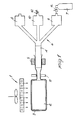
- the packaging apparatus comprises a heat source 1, which can supply heat, for example either by convection or radiation.
- a heat source an electric resistance heater combined with a blower will be used.
- a product 2 to be packaged is introduced into a container 3 formed of a flexible thermoplastic material of a heat-shrinkable nature either manually or through conventional loading means for such applications, not shown.
- the container with the product to be packaged inside it, is positioned at a nozzle 4, it being, for example, fed by a specially provided conveyor, e.g. a belt conveyor.
- a suitable clamp 5 provides a tight fit of the mouth of the container 3 onto the nozzle 4.
- the nozzle 4 is in communication through a valve 8, with a suction means such as a vacuum pump (not shown), and is also in communication with a means 7 of injecting a pressurised gas, for example, through a three-way connector, generally indicated at 6.
- Specially provided valves 8 and 9 control the opening and/or closing of said suction means and injection means.
- the nozzle 4 also communicates with the outside atmosphere through a third cut-off valve 10 and additional vent valve 12 connected thereto.
- a sealing means 11 is arranged either to heat seal the neck or mouth of the container 3 on completion of the packaging operation, or to apply a strap or clip thereon.
- the sealing means may comprise heated pressure sealing bars, or as an alternative, where the material of the container 3 is of the self-sealing type, a means of sealing by mere heat application. Alternatively, conventional clipping means may be used.
- the packaging method of this invention will be next described with reference to Figure 2.
- the container enclosing the product to be packaged is inserted with its mouth over the nozzle 4, and the clamp 5 is tightened around the container mouth to provide a perfect seal between the container and nozzle.
- the insulating gas of the following step is other than air, e.g. nitrogen or CO 2
- a pre-evacuation step is carried out at this time.
- the valve 8 is opened to put the interior of the container 3 into communication with the vacuum pump, the valves 9 and 10 being held closed. As air is removed from the space between the product 2 and container 3, the latter will collapse to contact the surface of the product 2.
- the insulating gas injection sequence On completion of the air removal step, the insulating gas injection sequence, indicated at B, takes place. Where the insulating gas is air, the pre-evacuation step would be omitted, and the cycle would be resumed by directly going to the gas injection step.
- the valve 9 is opened to admit pressurised gas from the pressure bottle 7 (Fig. 1) through a pressure reducer (14) into the space between the container 3 and product 2.
- the gas injection step is continued until the walls of the container 3 bulge out and separate completely from the surface of the product 2, to be insulated therefrom by the gas layer.
- the gas pressure at this stage will be the least required to fully detach the container walls from the product, and such as to avoid rupture of the walls.
- the pressure level may range, for example, from 200 to 10,000 Pa.
- the operative sequence indicated at C in the drawing takes place, wherein heat begins to be applied by means of the heat source 1 and the valves 8 and 9 are closed and the cut-off valve 10 opened.
- the container 3 undergoes a heat-shrinking effect which causes the previously introduced insulating gas to be discharged through the cut-off valve 10 and vent valve 12 whereby the walls of the container 3 collapse down to contact the surface of the product 2.
- quick heating of the bag walls can be achieved without the heating rate being hindered by the thermal inertia of the product 2 placed inside the container, owing to the provision of the insulating gas between the product and container.
- the product 2 is a chilled or frozen product, separation of the bag walls from the product by the gas provides insulation so the wall can be heated throughout its thickness. Otherwise the chilled product in contact with the bag wall acts as a heat sink.
- vent valve 12 The exit of gas from the container is initiated by the shrinking and is appropriately controlled through the vent valve 12, which is calibrated for a preset pressure level dependent on the container size, the material of which it is constructed, and its heat-shrinking temperature. Said vent valve 12 can prevent, during the heat shrinking process, both rupture of the container as caused by excess pressure, and a too high rate of gas removal. In fact, if the container is emptied quickly before its walls have reached their heat-shrinking temperature, the result will be an inadequate heat-shrinking.
- the heat-shrinking step may be completed, as illustrated by the sequence indicated at D, by continued application of heat and by opening the valve 8 connected to the vacuum suction system, while closing at the same time the cut-off valve 10.
- the sequence D is specially useful where the product being packaged is of a perishable nature.
- the package sealing step takes place, for example, by heat sealing using the sealing bars 11.
- the excess portion of the container walls is cut off and removed from the nozzle after releasing the clamp 5. Heating is continued to completion of the heat-shrinking process also at the mouth area after sealing.
- the material useful for the container in the inventive method is any thermoplastic material exhibiting heat-shrinking properties, and possibly heat welding properties.
- Single layer films may be used such as biaxially oriented, radiation cross-linked, polyethylene films like the films sold by W. R. Grace & Co. as "D-FILM” or as “CRY-OVAC D-FILM” (Trademarks of W. R. Grace & Co.) or bi-oriented plastified polyvinylidene chloride, like the one sold by W. R. Grace & Co. "S-FILM” (Trademark of W. R. Grace & Co.).
- multilayered films which have at least one heat-shrinkable layer and additional layers performing the function of a heat welding layer, of a gas barrier, etc., depending on the final use contemplated.
- a heat-shrinkable layer bi-oriented polyvinylidene chloride and copolymers thereof with ethylenically unsaturated monomers, fluorocarbon polymers, and fluorohydrocarbon polymers, may be used.
- a polyvinyl acetate or EVA (ethylene-vinyl acetate) copolymer may, for example, be used.
- the packaging material may moreover comprise additional intermediate layers, e.g. of polyvinylidene chloride, nylon, etc.
- An example of a multilayer film useful with this invention is an oriented film having layers of irradiated ethylene-vinyl acetate copolymer/viny- lidene chloride copolymer/ethylene-vinyl acetate, or a biaxially oriented film having layers of nylon/ nylon/irradiated polyethylene.
- the container used with this invention may be in the form of a wrapping sheet to be folded up in the process, or may be seamless tubing closed at one end, or may be a preformed bag.
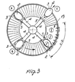
- Figure 3 of the drawings shows an alternative embodiment of an apparatus according to this invention, which allows the inventive process to be carried out in a semi-continuous or continuous fashion.
- the apparatus comprises a plurality of nozzles, e.g. four, which are mounted pivotally about a vertical centre axis, each of them being communicated to a vacuum pump, an insulating gas blowing means, a cut-off valve, and a vent valve, as described hereinabove.
- Timers control appropriately the opening and closing sequence of the various control valves to enable each nozzle to complete its processing cycle, as described with reference to Figure 2, in an independent and non- synchronous manner with respect to the other nozzles.
- Each nozzle performs a complete processing cycle during its full revolution about the vertical axis, so that upon returning to its starting point, or station A, a nozzle is ready to receive a fresh container with a product to be packaged therein and to complete a further revolution to go through all of the processing sequences B-C-D-E, the finished package being discharged at the point illustrated as station E.
- the heating and heat-shrinking step is expediently effected by passing the rotating nozzles through a heattunnel, preferably a convective hot air tunnel but radiation may also be employed, as indicated at 13.
- electric resistors and blowers may, for example, be provided inside the tunnel, and arranged evenly across the side and top walls of the tunnel.
- an existing multistation apparatus such as the "Girovac” (Trademark of W. R. Grace & Co.) machine from W. R. Grace & Co. or "Roto-Matic” machine from Tipper-Tie Division of Rheem Manufacturing Company, but equipped additionally with all the necessary facilities mentioned above, i.e., a hot air tunnel, heat welding bars and, for each nozzle, a cut-off valve and vent valve.
- a hot air tunnel i.e., a hot air tunnel, heat welding bars and, for each nozzle, a cut-off valve and vent valve.
- a bag is used of a biaxially oriented heat-shrinkable material, of the type available commercially under the trademark "Barrier Bag” and being distributed by W. R. Grace & Co.
- Said material comprises an outer surface layer of irradiated ethylene-vinyl acetate copolymer, an intermediate, gas impervious layer of plastified vinylidene chloride copolymer, and an inner surface layer of heat sealable ethylene-vinyl acetate copolymer.
- a product is introduced into the container. In this specific case, a cut of cooked ham is packaged. Next, by means of a sealing clamp, the bag mouth is inserted over a nozzle of a multistation machine, as shown in Figure 3.
- the container with the product therein is secured and sealed to the nozzle.
- the product being packaged is conveyed over a surface provided with rotating rollers, while through the nozzle, during the step B, air at a pressure of 1.96 KPa is introduced.
- This pressure can be controlled accurately, for example, with a manostat which automatically closes the gas intake valve upon reaching a preset level.
- the cut-off vent valve is closed.
- the ham cut being packaged is then started along a hot air heating tunnel 13 which has sufficient length to provide perfect heat shrinkage. Heating is accomplished by means of an electric resistance device incorporating a fan, such as "Leister Forte S" unit or similar unit of 10,000 watts.
- the tunnel interior temperature is about 170°C.
- a residence time in the tunnel of 4-5 seconds is adequate to provide full heat shrinkage.
- the cut-off valve 10 is opened.
- the outflow of the gas contained in the container is appropriately controlled by the vent valve 12, which includes a calibration spring arrangement effective to prevent rupture of the container as well as too fast a removal of the air.
- the vent valve opens fully to allow out all of the contained air.
- the cycle may be terminated at this point by closing the container with a clip or by heat sealing.
- a gas removal step may be provided through the vacuum forced suction system. This additional step is particularly suitable for stronger products where the shrink forces in the wrapping material will not distort the product.
- the method disclosed herein affords the achievement of a quick and effective heat shrinkage owing to the absence of contact during the heating and shrinking step between the container material and the product, and, therefore, the absence of heat dissipation to the product. Further, this method is more promising from the standpoint of preservation of the packaged product, owing to the insulating gas introduction step ensuring complete removal of the air from the container. Moreover, the presence of the insulating gas layer during the first heating step allows just slight heating of the product and contributes, in turn, to an improved preservation of the product.
- the "insulating gas" used in the method of the present invention is a gas, preferably an inert gas, which thermally insulates by expanding the bag and placing the bag out-of-contact with the product, i.e., the gas separates the bag and product so that the product will not chill the bag and keep it from being heated to its shrinkable temperature.
Landscapes
- Engineering & Computer Science (AREA)
- Mechanical Engineering (AREA)
- Chemical & Material Sciences (AREA)
- Dispersion Chemistry (AREA)
- Vacuum Packaging (AREA)
Claims (11)
Applications Claiming Priority (2)
| Application Number | Priority Date | Filing Date | Title |
|---|---|---|---|
| GB8323273 | 1983-08-31 | ||
| GB08323273A GB2145686B (en) | 1983-08-31 | 1983-08-31 | A method and apparatus for packaging in flexible heat-shrinkable containers |
Publications (2)
| Publication Number | Publication Date |
|---|---|
| EP0150554A1 EP0150554A1 (de) | 1985-08-07 |
| EP0150554B1 true EP0150554B1 (de) | 1988-03-16 |
Family
ID=10548070
Family Applications (1)
| Application Number | Title | Priority Date | Filing Date |
|---|---|---|---|
| EP84304145A Expired EP0150554B1 (de) | 1983-08-31 | 1984-06-19 | Verfahren und Vorrichtung zum Verpacken in flexible warm-schrumpffähige Verpackungen |
Country Status (8)
| Country | Link |
|---|---|
| EP (1) | EP0150554B1 (de) |
| JP (1) | JPS6068226A (de) |
| AU (1) | AU572176B2 (de) |
| BR (1) | BR8404321A (de) |
| DE (1) | DE3469877D1 (de) |
| GB (1) | GB2145686B (de) |
| NZ (1) | NZ209107A (de) |
| ZA (1) | ZA846120B (de) |
Families Citing this family (10)
| Publication number | Priority date | Publication date | Assignee | Title |
|---|---|---|---|---|
| FR2588828B1 (fr) * | 1985-10-23 | 1988-05-20 | Sleever Int | Procede et appareil pour l'application, par retraction, d'un troncon de gaine thermoretractable autour d'objets a revetir |
| IT1197311B (it) * | 1985-11-08 | 1988-11-30 | Argatom Ing Constr | Procedimento per aumentare la durata di conservazione del pesce |
| DE8804219U1 (de) * | 1988-03-29 | 1988-05-19 | W. Kordes' Söhne Rosenschulen GmbH & Co KG, 25365 Klein Offenseth-Sparrieshoop | Versandbehälter insbes. für Pflanzen od. dgl. |
| JP2900095B2 (ja) * | 1991-02-26 | 1999-06-02 | 茨木精機株式会社 | 包装方法及び装置 |
| AU658078B2 (en) * | 1992-09-08 | 1995-03-30 | Kureha Corporation | Divided package of adsorbent for internal use and process for producing the same |
| US8256190B2 (en) | 1998-09-10 | 2012-09-04 | The Bowden Group | System and method for providing a regulated atmosphere for packaging perishable goods |
| US7644560B2 (en) * | 1998-09-10 | 2010-01-12 | The Bowden Group | System and method for providing a regulated atmosphere for packaging perishable goods |
| US8783002B2 (en) | 1998-09-10 | 2014-07-22 | The Bowden Group | Method for providing a regulated atmosphere for packaging perishable goods |
| EP1207041A1 (de) * | 2000-11-20 | 2002-05-22 | Transhield AS | Material und Verfahren zum Schutz von Gegenständen |
| CZ13585U1 (cs) * | 2003-03-21 | 2003-08-18 | Jan Ing. Mašek | Zařízení na dosažení hlubokého vakua |
Family Cites Families (5)
| Publication number | Priority date | Publication date | Assignee | Title |
|---|---|---|---|---|
| DE2247452A1 (de) * | 1972-09-27 | 1974-04-04 | Hagedorn Kg Technopack Ewald | Verfahren und vorrichtung zum evakuieren und verschliessen eines verpackungsbeutels |
| AU497624B2 (en) * | 1975-06-12 | 1978-12-21 | W.R. Grace Australia Limited | Packaging of animal carcasses |
| JPS5323785A (en) * | 1976-08-12 | 1978-03-04 | Toppan Printing Co Ltd | Gas displacing/sealing device for packed body |
| IE51047B1 (en) * | 1980-06-25 | 1986-09-17 | Grace W R & Co | Packaging process and apparatus |
| IE52224B1 (en) * | 1981-03-18 | 1987-08-19 | Grace W R & Co | Packaging process and apparatus |
-
1983
- 1983-08-31 GB GB08323273A patent/GB2145686B/en not_active Expired
-
1984
- 1984-06-19 EP EP84304145A patent/EP0150554B1/de not_active Expired
- 1984-06-19 DE DE8484304145T patent/DE3469877D1/de not_active Expired
- 1984-08-03 NZ NZ209107A patent/NZ209107A/en unknown
- 1984-08-06 AU AU31635/84A patent/AU572176B2/en not_active Ceased
- 1984-08-07 ZA ZA846120A patent/ZA846120B/xx unknown
- 1984-08-24 JP JP59175327A patent/JPS6068226A/ja active Pending
- 1984-08-29 BR BR8404321A patent/BR8404321A/pt unknown
Also Published As
| Publication number | Publication date |
|---|---|
| NZ209107A (en) | 1986-08-08 |
| GB2145686B (en) | 1987-06-10 |
| EP0150554A1 (de) | 1985-08-07 |
| ZA846120B (en) | 1985-03-27 |
| BR8404321A (pt) | 1985-07-30 |
| GB2145686A (en) | 1985-04-03 |
| GB8323273D0 (en) | 1983-10-05 |
| AU572176B2 (en) | 1988-05-05 |
| JPS6068226A (ja) | 1985-04-18 |
| DE3469877D1 (en) | 1988-04-21 |
| AU3163584A (en) | 1985-03-07 |
Similar Documents
| Publication | Publication Date | Title |
|---|---|---|
| US4457122A (en) | Vacuum packaging goods in heat shrinkable plastic bags using flexible diaphragms | |
| US4471599A (en) | Packaging process and apparatus | |
| AU2003240246B2 (en) | Packaging method and device | |
| US4550548A (en) | Method and apparatus for vacuum packaging with preshrinking | |
| US5664408A (en) | Apparatus for vacuum packaging a soft product | |
| US4545177A (en) | Packing process and apparatus | |
| US4132048A (en) | Vacuum packaging bulk commodities | |
| GB2152897A (en) | Heat shrink packaging | |
| IE45916B1 (en) | Vacuum packing method and apparatus | |
| EP0150554A1 (de) | Verfahren und Vorrichtung zum Verpacken in flexible warm-schrumpffähige Verpackungen | |
| US4958480A (en) | High profile shrink package | |
| US2348176A (en) | Packaging process | |
| CA1247515A (en) | Method and apparatus for vacuum packaging goods in heat shrinkable plastic bags | |
| FR2588828A1 (fr) | Procede et appareil pour l'application, par retraction, d'un troncon de gaine thermoretractable autour d'objets a revetir | |
| GB2078658A (en) | Vacuum packaging process and apparatus | |
| IE52224B1 (en) | Packaging process and apparatus | |
| EP0176514A1 (de) | Verpacken von nahrungsmitteln. | |
| EP0745539A1 (de) | Leicht zu öffnende Verpackung, insbesondere für Lebensmittel und Verfahren zu deren Herstellung | |
| MXPA96002024A (en) | Packaging for an article as a food substance that can be opened easily and method to produce this packaging | |
| US3171238A (en) | Sealing method | |
| EP0056345A1 (de) | Verpackungsverfahren und -vorrichtung für Produkte der industriellen Bäckerei mit einer mittelmässigen Feuchtigkeit | |
| JPH0648424A (ja) | 包装容器の製造方法及び包装容器の製造装置 | |
| JP2001180623A (ja) | シュリンク包装方法及び該方法に用いる熱収縮性フィルム | |
| GB2052429A (en) | Method of sealing retortable pouches | |
| GB1562392A (en) | Packaging of foodstuffs |
Legal Events
| Date | Code | Title | Description |
|---|---|---|---|
| PUAI | Public reference made under article 153(3) epc to a published international application that has entered the european phase |
Free format text: ORIGINAL CODE: 0009012 |
|
| AK | Designated contracting states |
Designated state(s): AT BE CH DE FR IT LI LU NL SE |
|
| 17P | Request for examination filed |
Effective date: 19850531 |
|
| GRAA | (expected) grant |
Free format text: ORIGINAL CODE: 0009210 |
|
| AK | Designated contracting states |
Kind code of ref document: B1 Designated state(s): CH DE FR IT LI NL |
|
| REF | Corresponds to: |
Ref document number: 3469877 Country of ref document: DE Date of ref document: 19880421 |
|
| ITF | It: translation for a ep patent filed | ||
| ET | Fr: translation filed | ||
| PLBE | No opposition filed within time limit |
Free format text: ORIGINAL CODE: 0009261 |
|
| STAA | Information on the status of an ep patent application or granted ep patent |
Free format text: STATUS: NO OPPOSITION FILED WITHIN TIME LIMIT |
|
| 26N | No opposition filed | ||
| NLT1 | Nl: modifications of names registered in virtue of documents presented to the patent office pursuant to art. 16 a, paragraph 1 |
Owner name: W.R. GRACE & CO.-CONN. TE NEW YORK, NEW YORK, VER. |
|
| PGFP | Annual fee paid to national office [announced via postgrant information from national office to epo] |
Ref country code: NL Payment date: 19900630 Year of fee payment: 7 |
|
| PGFP | Annual fee paid to national office [announced via postgrant information from national office to epo] |
Ref country code: CH Payment date: 19910627 Year of fee payment: 8 |
|
| ITTA | It: last paid annual fee | ||
| PG25 | Lapsed in a contracting state [announced via postgrant information from national office to epo] |
Ref country code: NL Effective date: 19920101 |
|
| NLV4 | Nl: lapsed or anulled due to non-payment of the annual fee | ||
| PG25 | Lapsed in a contracting state [announced via postgrant information from national office to epo] |
Ref country code: LI Effective date: 19920630 Ref country code: CH Effective date: 19920630 |
|
| REG | Reference to a national code |
Ref country code: CH Ref legal event code: PL |
|
| PGFP | Annual fee paid to national office [announced via postgrant information from national office to epo] |
Ref country code: FR Payment date: 19930609 Year of fee payment: 10 |
|
| PGFP | Annual fee paid to national office [announced via postgrant information from national office to epo] |
Ref country code: DE Payment date: 19930630 Year of fee payment: 10 |
|
| PG25 | Lapsed in a contracting state [announced via postgrant information from national office to epo] |
Ref country code: FR Effective date: 19950228 |
|
| PG25 | Lapsed in a contracting state [announced via postgrant information from national office to epo] |
Ref country code: DE Effective date: 19950301 |
|
| REG | Reference to a national code |
Ref country code: FR Ref legal event code: ST |