EP0150183B1 - Verfahren und gerät zur feststellung der herkunft von gesprächen - Google Patents
Verfahren und gerät zur feststellung der herkunft von gesprächen Download PDFInfo
- Publication number
- EP0150183B1 EP0150183B1 EP83903626A EP83903626A EP0150183B1 EP 0150183 B1 EP0150183 B1 EP 0150183B1 EP 83903626 A EP83903626 A EP 83903626A EP 83903626 A EP83903626 A EP 83903626A EP 0150183 B1 EP0150183 B1 EP 0150183B1
- Authority
- EP
- European Patent Office
- Prior art keywords
- station
- call
- calling
- called
- directory number
- Prior art date
- Legal status (The legal status is an assumption and is not a legal conclusion. Google has not performed a legal analysis and makes no representation as to the accuracy of the status listed.)
- Expired
Links
- 238000000034 method Methods 0.000 title claims abstract description 11
- 238000004891 communication Methods 0.000 claims abstract description 16
- 230000004044 response Effects 0.000 claims description 5
- 238000010586 diagram Methods 0.000 description 6
- 238000012545 processing Methods 0.000 description 6
- 230000011664 signaling Effects 0.000 description 6
- 239000004020 conductor Substances 0.000 description 3
- 230000006870 function Effects 0.000 description 3
- 230000002093 peripheral effect Effects 0.000 description 3
- 238000013519 translation Methods 0.000 description 3
- 238000013475 authorization Methods 0.000 description 2
- 230000005540 biological transmission Effects 0.000 description 1
- 238000010276 construction Methods 0.000 description 1
- 238000001514 detection method Methods 0.000 description 1
- 230000010365 information processing Effects 0.000 description 1
- 238000009434 installation Methods 0.000 description 1
- 238000012423 maintenance Methods 0.000 description 1
- 238000012544 monitoring process Methods 0.000 description 1
- 238000012216 screening Methods 0.000 description 1
Images


Classifications
-
- H—ELECTRICITY
- H04—ELECTRIC COMMUNICATION TECHNIQUE
- H04Q—SELECTING
- H04Q3/00—Selecting arrangements
- H04Q3/72—Finding out and indicating number of calling subscriber
Definitions
- This invention relates to apparatus for providing a call tracing service for use with a telephone system having a communications terminal and serving a plurality of stations.
- tracing a call through a telephone switching system to identify the calling station has typically included the assistance of telephone company personnel.
- a party receiving, for example, a nuisance call would have telephone company personnel notified to trace the identity of the calling station while the nuisance call continued.
- this required telephone company personnel to first translate the called station's directory number to an equipment location and then physically trace the call connection through the switching system to the calling station equipment location.
- the equipment location can easily be translated to a local calling station directory number.
- personnel in the distant switching system office would have to trace the call to the calling station or to still another office until the calling station is identified.
- the call tracing process may take a considerable period of time.
- the nuisance caller is not going to continue the call for any extended period of time particularly if the caller is trying to avoid detection.
- Switched program-controlled switching systems eliminate the need of physically tracing a call through an office; however, the problem of notifying telephone company personnel to trace a nuisance call is still required.
- the switching system program may be modified to identify all calls to a particular called station.
- specialized equipment at the telephone office may be utilized to identify nuisance callers; however, again, the need for arranging for this type of tracing equipment in advance of the nuisance call is required. Nevertheless, call tracing may still be thwarted when an interoffice nuisance call is made.
- Display station sets offer some relief to the problem of having to arrange for call tracing in advance.
- the station set which is usually associated with a private branch exchange displays the intraexchange calling station identity when the called station set is rung.
- the problem of identifying a nuisance caller is likewise thwarted with an interoffice call.
- the problem of generating a permanent record for the authorities also arises unless prior arrangements with telephone company personnel have made in advance. Even wtih a record of all calls to a particular called station, the problem of distinguishing which calls are nuisance presents itself unless the nuisance caller uses the same calling station.
- BE 697758 discloses an assembly for telecommunications installations.
- a called subscriber can secure the identification of the calling subscriber by dialing a code after the call.
- an authorization to issue such a command must be prerecorded in the central office. Without such authorization for each and every call, there will have to be recorded all of the pertinent information regarding the call-including each unit making up the connection from the calling . subscriber to the called subscriber. This would require a very substantial increase in memory capacity to accommodate this feature.
- the identity of the called station as well as the stored identity of the calling station is sent to the communications terminal.
- the identities of both the calling and called stations may be sent to the authorities when a code designating a call as nuisance or obscene is entered at the called station after the call is completed.
- the identity of the calling station may be indicated at the called station.
- each one of a plurality of calling stations may be stored and designated as that of a calling station.
- the designated identity of a calling station is then chosen per a predetermined algorithm and sent to the communications terminal.
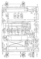
- Fig. 1 shows a block diagram of a typical switching network comprising telephone switching offices 100 and 101 which serve a plurality of customer stations such as 102, 103, 170 and 171.
- each of the telephone switching offices is suitably an electronic program-controlled switching system of the type disclosed in U.S. Pat. No. 3,570,008 to R. W. Downing et al. of March 9, 1971, and also disclosed in The Bell System Technical Journal, Vol. 43, No. 5, Parts 1 and 2, September, 1964.
- These citations may be referred to for a more comprehensive understanding of the construction and operation of the switching system, but a brief description will be given herein to illustrate how the invention functions within a switching system.
- Switching office 100 comprises line link network 104, trunk link network 105, and a stored program-controlled processor 108.
- Line link network 104 provides the terminations for customer stations, such as 102 and 170, while trunk link network 105 provides the terminations for trunks such as interoffice trunk 132 which is terminated at switching office 100 via trunk circuit 131.
- the trunk link network also provides terminations for miscellaneous other circuits such as digit receiver 107, announcement system 121, etc.
- the line and trunk link networks are connected via wire junctors 106 to permit the interconnection of lines, trunks, and service circuits for call processing under the control of processor 108.
- Line link network 104 is also interconnected by junctor circuits such as 154 to complete and supervise intraoffice calls between stations such as 102 and 170.
- central processor 108 The majority of the logic, control, storage, supervisory, and translation functions required for the operation of this system are performed by central processor 108.
- a typical central processor suitable for use in the illustrative switching system is described in The Bell System Technical Journal, Vol. 56, No. 2, February 1977.
- Processor 108 is a data processing facility and can be functionally divided into central control 109, call store 110, and program store 111 plus maintenance apparatus which has not been shown to simplify the drawing.
- Call store 110 is a memory for storing translation and routing information in addition to temporary information relating to calls in progress and special services. As will be described in more detail hereinafter, this temporary information includes the busylidle status of circuits and stations, callinglcalled station directory numbers, etc.
- call store 110 also includes memory dedicated to each customer station for storing on a per call basis information which is related to a calling station. This information includes the identity of the calling station such as the directory number and may also include the time of day, type of equipment, etc.
- the memory dedicated to each customer station also includes a station indicator for designating the information as that of either a "calling" or a "called" station. For example, responsive to a call from calling station 102 to called station 170, the station indicator for called station 170 is set to "calling" station such that call tracing service for other special services may be subsequently initiated. Similarly, the station indicator for calling station 102 is set to "called' station such that special feature associated with a calling station may be initiated.
- the indicator may also be extended to include various combinations of factors such as, for example, type of party (calling/called), group (PBX/ Centrex), or equipment; status of party, group, or equipment; screening treatment; etc.
- call store memory is dedicated to each customer station for storing on a per call basis, the calling station directory number.
- the memory also includes a station line indicator bit for designating the stored directory number as that of either a "calling" or a "called" station.
- Program store 111 is a memory for storing the program instructions which direct the central control to sequentially perform its many functions.
- Central control 109 is the information processing unit of the system and executes the program instructions listed in program store 111 using information temporarily stored in call store 110.
- Processor 108 interfaces with lines, trunks, and service circuits via scanners 112-114 and 153 and distributor 115.
- Distributor 115 responds to an order over a bus system from the central control to apply pulses to distribution points connected to peripheral units of equipment. For example, in response to an appropriate order, distributor 115 signals over conductor 116 to actuate apparatus such as a relay in trunk circuit 131.
- Scanners 112-114 and 153 are used to gather information for the central control by monitoring leads connected to the various peripheral units and customer stations.
- a trunk circuit such as 131 changes state as a result of a seizure from a distant originating switching office
- a signal is transmitted via conductor 117 to scanner 113.
- scanner 113 recognizes changes of state in digit receiver 107 via conductor 119 in order to ascertain digits received from lines or trunks.
- scanners 112 and 153 are used to recognize the busy/idle (off-hook/on-hook) condition of customer stations such as 102 and 170. Periodically, the scanners are addressed by central control 109 over a bus system to determine the state of the peripheral units and customer stations.
- processor 108 interfaces with communications terminal 181 for sending and receiving various types of administrative messages which may include, for example, the directory numbers of the calling and called stations associated with a call. These call tracing service messages may also be sent to a customer station which is connected to a processor-controlled service circuit.
- Switching office 101 basically comprises the same units of equipment as switching office 100 and need not be described herein.
- Switching offices 100 and 101 are connected together and to other switching offices via a common channel interoffice signaling (CCIS) system comprising terminals 124 and 127, data units 125 and 126, and data link 128.
- CCIS common channel interoffice signaling
- the signaling system provides high speed data transmission facilities between the central processors of offices 100 and 101 to carry all signaling, address, and network control information independently of the interoffice talking paths. For instance, this information includes the identity of trunks used by the customers as well as calling and called party identification.
- the method for providing call tracing service with this novel arrangement may be divided into two phases: storage and reporting.
- the directory number of the calling station is stored in a table entry which is associated with the called station and is referred to as the line history.
- the directory number of the called station is stored in a line history table entry which is associated with the calling station.
- an associated station indicator bit is set to designate the stored directory number as that of either a "calling" or a "called" station.
- the stored directory number of the calling station along with the indicator bit are then used for sending the stored directory number to appropriate personnel when the call has been, for example, obscene.
- the reporting phase is implemented by the customer entering a predetermined access code at the called station. Responsive to this access code, the stored directory number of the calling station is sent to a communications terminal for subsequent follow-up by appropriate personnel.
- the line history table entry need only be a single memory location to store one calling station directory number. However, when a station is provided with a number of special services or receives a large number of calls, a line history table entry capable of storing multiple directory numbers is desirable. As a result, the customer may first choose the directory number of the nuisance caller before sending the number to the communications terminal.
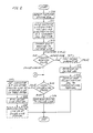
- the storage phase of the arrangement may be implemented in one of two manners.
- the customer at station 102 may lift his/her receiver to place a regular telephone call.
- scanner 112 recognizes the receiver of the calling station off hook (ROH) (block 200) and transmits this information to central control 109 which determines that this is a new request for service.
- central control 109 Having selected a temporary call register in call store 110, central control 109 enters call processing information such as line equipment number (LEN) and directory number (DN) of the calling station into the temporary call register (block 201).
- LN line equipment number
- DN directory number
- Fig. 5 Shown in Fig. 5 is the layout of a temporary call register in call store 110.
- This register is used by the central control to temporarily store call processing information.
- This information includes well-known general call processing data as well as specific data for intraoffice and interoffice calls.
- this specific data includes the dialed digits and the equipment and directory numbers of the calling station.
- this specific data includes the equipment number of the incoming trunk as well as the dialed digits.
- the distant calling line directory number is also included.
- digit receiver 107 is then connected to station 102 (block 202) via one at junctors 106. Dial tone is returned to the station, and the customer thereat dials or keys the directory number of the called station.
- Central control 109 reads the dialed digits received by digit receiver 107 via scanner 113 and stores them in the temporary call register. Under the control of a digit analysis program and through the use of translation tables in call store 110, central control 109 determines the disposition of the call. When the received digits correspond to an access code (block 203), central control 109 causes the arrangement to implement the reporting phase.
- central control 109 determines the busy/idle status of called station 170 via scanner 112 (block 205).
- busy tone circuit 151 sends a busy signal to calling station 102 (block 206).
- central control 109 stores the directory number of calling station 102 in the line history table entry associated with called station 170 and sets the indicator bit to "calling" station (block 207). The call then proceeds in a normal manner.
- Audible tone circuit 152 sends an audible ringing signal to calling customer station 102, and ringing service circuit 133 rings called station 170 (block 208).
- call waiting service When called station 170 has been provided with well-known call waiting service and is in a busy condition, the call is handled as if the called line were in an idle condition. Appropriately, audible ringing tone is sent to customer station 102, and a call waiting tone is sent to busy called station 170.
- the directory number of calling station 102 may be displayed in display 180 of called station 170 (phantom block 209) which may be any well-known and commercially available LED or the like display station set. Alternatively, the directory number of the calling station may be sent to station 170 in the form of a message from annoucement system 121.
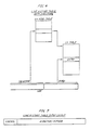
- the line history table is accessed using the line equipment number of the calling station which is stored in the temporary call register. As shown, a portion of the line equipment number is used to select the memory address of the particular line history table in the line history (LH) head table. With the beginning address of the selected line history table, the remaining portion of the line equipment number is used to index the entry of the table associated with the calling station.
- LH line history
- the layout of a single memory location line history table entry is depicted in Fig. 7.
- the single location entry includes control and directory number fields.
- the control field includes a station indicator bit which designates the directory number stored in the line history table entry as that of either a "calling" or a "called' station.
- a privacy bit is included in the control field to prevent disclosure of certain station numbers.
- the line history table entry for each associated customer in a switching office may include additional locations fashioned, for example, in a well-known push-down stack arrangement. These additional locations may be used for storing information such as time of call; type of equipment; etc.
- each line history table entry may include two push-down stacks for separately storing called and calling station directory numbers.
- These multiple memory location table entries may be used with multiple access codes to enhance the novel arrangement which will be described hereinafter.
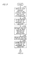
- Fig. 3 Depicted in Fig. 3 is the other manner in which to implement the storage phase when called station 170 receives an incoming interoffice call.
- switching office 100 now a terminating office, receives a CCIS initial address message identifying the interoffice trunk and the directory number of the called customer station (block 300).
- CCIS initial address message identifying the interoffice trunk and the directory number of the called customer station (block 300).
- calling station 103 at originating switching office 101 wishes to connect to called station 170 at terminating switching office 100.
- the call is initiated by originating switching office 101 by sending a well-known CCIS banded-type signaling service request message to terminating switching office 100.
- processor 108 enters the called line directory number in a temporary call register (block 301).
- Processor 108 then translates the called line directory number to a line equipment number for the called station. While completing the call, central control 109 also composes a CCIS message requesting the directory number of the calling station from the originating swtiching office (block 302). Alternatively, the calling line directory number may be included in the initial service request message.
- the CCIS request message is processed to ascertain the directory number of calling station 103.
- the directory number along with interoffice trunk number 132 is transmitted via the CCIS system to terminating switching office 100.
- central control 109 receives the calling line directory number (block 303), central control 109 enters the calling line directory number in the temporary call register associated with the call (block 304).
- central control 109 determines the busy/idle status of the local called station as depicted in decision block 205 of Fig. 2.
- an audible busy signal is sent to calling station 103 (block 206).
- central control 109 When called station 170 is in an idle condition or has been provided with call waiting service, central control 109 stores the directory number of the calling station in the temporary call register into the line history table entry associated with the called line and sets the indicator bit to "calling" station (block 207). Ringing service circuit 133 provides ringing current to called station 170 (block 208), and audible tone circuit 152 sends an audible ringing signal to calling station 103. As previously suggested, the directory number of calling station 103 may also be indicated at called station 170 by the use of an LED or the like station set.
- the calling station directory number is stored in the line history table entry associated with the called station.
- the station indicator bit is set to "calling" station to designate the stored directory number as that of a calling station.
- the line history table entry for a customer station may comprise a single memory location or any number of memory locations each for storing a calling directory number.
- the reporting phase of the call tracing service is implemented when a customer having received, for example, an obscene call wants to send the directory number of the calling station to appropriate personnel for subsequent follow-up.
- the customer at called station 170 implements the reporting phase of the call tracing service by lifting his/her receiver after terminating the obscene call in a standard manner and keying a call tracing service access code.
- This access code may be a special 2 or 3 digit number and, in order to distinguish it from other codes, could include the star ( * ) or pound (#) found on a telephone key set.
- a single code may be provided to retrieve stored directory numbers designated as "calling" station per a predetermined algorithm such as , for example, the order in real time in which the directory numbers were designated as "calling" stations.
- scanner 112 recognizes the receiver of station 170 off hook (ROH) and sends this information to central control 109 which enters the line equipment and directory numbers of station 170 in a temporary call register of call store 110.
- Central control 109 then connects digit receiver 107 to the customer station, and the customer there keys the call tracing service access code which indicates that the stored directory number of the calling station be sent to the appropriate personnel for follow up.
- the line history table entry associated with the customer station comprises a single memory location for storing called and calling line directory numbers. A table entry having multiple memory locations will be described hereinafter (phantom call block 210).
- the illustrated single location table entry arrangement requires only one access code.
- central control 109 retrieves the designated "calling" station directory number stored in the line history table entry associated with the called station (block 211) and sends it along with the called station's directory number to communications terminal 181 (block 212).
- the two directory numbers are displayed and a record made thereof for follow up by appropriate personnel.
- multiple memory locations for the line history table entry associated with a customer may be provided to store a number of calling and called directory numbers in a push-down stack arrangement.
- an access subroutine as shown in Fig. 4 may be utilized to choose a "calling" station based on the station indicator and then display the chosen number before sending it to the communications terminal.
- the access subroutine is called (phantom block 207).
- central control 109 retrieves the called/ calling directory number and associated indicator bit from the top of the line history stack. The indicator bit is examined to determine whether or not the stored directory number is "calling" (block 402).
- the directory number is indicated to the requesting customer (block 403).
- the calling directory number may be indicated to the customer in the form of a message from announcement system 121 or by a display at the customer station set.
- the requesting customer decides whether to report the calling directory number or select the next calling directory number in the stack by entering an appropriate code (block 404).
- central control retrieves the next entry in the line history stack when additional entries are available (blocks 405 and 406) or gives an end of list indication to the customer (block 407).
Landscapes
- Engineering & Computer Science (AREA)
- Computer Networks & Wireless Communication (AREA)
- Exchange Systems With Centralized Control (AREA)
- Telephonic Communication Services (AREA)
Claims (6)
Applications Claiming Priority (2)
| Application Number | Priority Date | Filing Date | Title |
|---|---|---|---|
| US06/512,956 US4591665A (en) | 1983-07-12 | 1983-07-12 | Method and apparatus for providing call tracing service |
| US512956 | 1995-08-09 |
Publications (2)
| Publication Number | Publication Date |
|---|---|
| EP0150183A1 EP0150183A1 (de) | 1985-08-07 |
| EP0150183B1 true EP0150183B1 (de) | 1987-11-11 |
Family
ID=24041321
Family Applications (1)
| Application Number | Title | Priority Date | Filing Date |
|---|---|---|---|
| EP83903626A Expired EP0150183B1 (de) | 1983-07-12 | 1983-08-29 | Verfahren und gerät zur feststellung der herkunft von gesprächen |
Country Status (6)
| Country | Link |
|---|---|
| US (1) | US4591665A (de) |
| EP (1) | EP0150183B1 (de) |
| JP (1) | JPS61500094A (de) |
| CA (1) | CA1220265A (de) |
| DE (1) | DE3374513D1 (de) |
| WO (1) | WO1985000494A1 (de) |
Families Citing this family (19)
| Publication number | Priority date | Publication date | Assignee | Title |
|---|---|---|---|---|
| BR8106464A (pt) * | 1981-10-02 | 1983-09-13 | Sonintel Sociedade Nacional De | Detector de chamada telefonicas |
| US6678360B1 (en) | 1985-07-10 | 2004-01-13 | Ronald A. Katz Technology Licensing, L.P. | Telephonic-interface statistical analysis system |
| US4845739A (en) | 1985-07-10 | 1989-07-04 | Fdr Interactive Technologies | Telephonic-interface statistical analysis system |
| US5359645A (en) | 1985-07-10 | 1994-10-25 | First Data Corporation Inc. | Voice-data telephonic interface control system |
| US5898762A (en) * | 1985-07-10 | 1999-04-27 | Ronald A. Katz Technology Licensing, L.P. | Telephonic-interface statistical analysis system |
| US5828734A (en) | 1985-07-10 | 1998-10-27 | Ronald A. Katz Technology Licensing, Lp | Telephone interface call processing system with call selectivity |
| US5793846A (en) | 1985-07-10 | 1998-08-11 | Ronald A. Katz Technology Licensing, Lp | Telephonic-interface game control system |
| WO1987006421A1 (en) * | 1986-04-08 | 1987-10-22 | Australian Telecommunications Commission | Telephone exchange with calling telephone identification |
| US4810331A (en) * | 1987-10-13 | 1989-03-07 | The Clorox Company | Surfactant sensing electrode for potentiometric titrations |
| US4924491A (en) * | 1988-11-18 | 1990-05-08 | American Telephone And Telegraph Company | Arrangement for obtaining information about abandoned calls |
| US5121423A (en) * | 1989-07-13 | 1992-06-09 | Sharp Kabushiki Kaisha | Communication unit comprising caller identification function and caller identifying method in a digital communication network |
| US5033076A (en) * | 1990-01-31 | 1991-07-16 | At&T Bell Laboratories | Enhanced privacy feature for telephone systems |
| US5235630A (en) * | 1991-04-17 | 1993-08-10 | Telident, Incorporated | Emergency call station identification system and method |
| CA2091080C (en) * | 1992-04-20 | 1999-03-09 | Amotz Bar-Noy | Tracking of mobile stations in wireless networks |
| US5559868A (en) * | 1993-08-30 | 1996-09-24 | Lucent Technologies Inc. | Method for sending and receiving video images |
| US5999616A (en) | 1998-04-17 | 1999-12-07 | Ameritech Services, Inc. | Method and system for call tracing |
| US5930344A (en) * | 1997-10-14 | 1999-07-27 | At & T Corp. | Method and apparatus for tracing a specific communication |
| KR100295832B1 (ko) | 1999-04-28 | 2001-07-12 | 박종섭 | 통화 채널 호 설정 메시지의 추적 방법 |
| US6771950B1 (en) * | 2000-09-12 | 2004-08-03 | Qwest Communications International Inc. | Method and system for a wireless subscriber to initiate a calling party number trace |
Family Cites Families (17)
| Publication number | Priority date | Publication date | Assignee | Title |
|---|---|---|---|---|
| US3546389A (en) * | 1965-12-13 | 1970-12-08 | Int Standard Electric Corp | Telecommunication switching system |
| DE1301842B (de) * | 1966-04-29 | 1969-08-28 | Siemens Ag | Verfahren fuer Fernmelde-, insbesondere Fernsprechanlagen mit Wegedatenspeicherung |
| DE2806234C2 (de) * | 1978-02-14 | 1984-03-08 | Siemens AG, 1000 Berlin und 8000 München | Schaltungsanordnung für eine Fernsprechanlage, mit einem Speicher für die Rufnummern vergeblich anrufender Sprechstellen |
| ES477175A1 (es) * | 1978-02-14 | 1979-07-16 | Siemens Ag | Una disposicion de circuito para una instalacion telefonica. |
| DE2820971A1 (de) * | 1978-05-12 | 1979-11-15 | Siemens Ag | Schaltungsanordnung fuer fernsprechvermittlungsanlagen mit verbindungsindividuellen einrichtungen und mit identifizierern |
| JPS5583367A (en) * | 1978-12-20 | 1980-06-23 | Hitachi Ltd | Malicious call search system |
| JPS55100779A (en) * | 1979-01-26 | 1980-07-31 | Nec Corp | Detection system for information on originating subscriber |
| US4277649A (en) * | 1980-01-18 | 1981-07-07 | Bell Telephone Laboratories, Incorporated | Method and apparatus for screening telephone calls |
| US4310726A (en) * | 1980-02-04 | 1982-01-12 | Bell Telephone Laboratories, Incorporated | Method of identifying a calling station at a call terminating facility |
| US4355207A (en) * | 1980-05-30 | 1982-10-19 | Amtel Communications, Inc. | Telephone answering system |
| JPS5731255A (en) * | 1980-08-01 | 1982-02-19 | Fujitsu Ltd | Automatic tracking system of call subscriber |
| JPS5745766A (en) * | 1980-09-01 | 1982-03-15 | Nec Corp | Detecting system for malicious call subscriber number |
| DE3034986C2 (de) * | 1980-09-17 | 1987-01-02 | Telefonbau Und Normalzeit Gmbh, 6000 Frankfurt | Verfahren zum Speichern und Anzeigen von Rufnummern anrufender Teilnehmer bei einer angerufenen unbesetzten Teilnehmerstelle in Fernsprechvermittlungs- insbesondere Fernsprechnebenstellenanlagen |
| JPS57141066A (en) * | 1981-02-24 | 1982-09-01 | Hitachi Denshi Ltd | Capstan control system for magnetic recording and reproducing device |
| IT1148027B (it) * | 1981-03-03 | 1986-11-26 | Cselt Centro Studi Lab Telecom | Sistema per la propagazione lungo un collegamento telefonico dell i dentita degli utenti interessati a tale collegamento |
| CA1217550A (en) * | 1981-10-02 | 1987-02-03 | Jose P. Pintos | Calling line tracing system and identification detector |
| JPS5866456A (ja) * | 1981-10-16 | 1983-04-20 | Hitachi Ltd | 悪意呼発信番号通知方式 |
-
1983
- 1983-07-12 US US06/512,956 patent/US4591665A/en not_active Expired - Lifetime
- 1983-08-29 EP EP83903626A patent/EP0150183B1/de not_active Expired
- 1983-08-29 WO PCT/US1983/001313 patent/WO1985000494A1/en not_active Ceased
- 1983-08-29 DE DE8383903626T patent/DE3374513D1/de not_active Expired
- 1983-08-29 JP JP58503651A patent/JPS61500094A/ja active Pending
-
1984
- 1984-06-26 CA CA000457420A patent/CA1220265A/en not_active Expired
Also Published As
| Publication number | Publication date |
|---|---|
| DE3374513D1 (en) | 1987-12-17 |
| EP0150183A1 (de) | 1985-08-07 |
| JPS61500094A (ja) | 1986-01-16 |
| WO1985000494A1 (en) | 1985-01-31 |
| CA1220265A (en) | 1987-04-07 |
| US4591665A (en) | 1986-05-27 |
Similar Documents
| Publication | Publication Date | Title |
|---|---|---|
| EP0151117B1 (de) | Methode und gerät zur verschaffung mehrerer sonderdienste | |
| EP0150183B1 (de) | Verfahren und gerät zur feststellung der herkunft von gesprächen | |
| US5631950A (en) | Transmission of data message during silent intervals of ringing for selection of terminal equipment | |
| US4310727A (en) | Method of processing special service telephone calls | |
| US4277649A (en) | Method and apparatus for screening telephone calls | |
| US4565903A (en) | Telephone interexchange carrier selection | |
| US4555594A (en) | Telephone interexchange signaling protocol | |
| US5018191A (en) | Special service call routing | |
| US5282243A (en) | Recording of automatic number identification to identify lost customers | |
| CA2191158C (en) | Screening of incoming telephone calls prior to call completion to the destination party | |
| US5506890A (en) | Method and apparatus for group-specific calling | |
| EP0590863A2 (de) | Nebenstellenanlagennetze | |
| US6330323B1 (en) | Enhanced overflow call processing | |
| AU7803487A (en) | Automatic speech recognition to select among call destinations | |
| US3854013A (en) | Call forwarding arrangement | |
| US4811378A (en) | Toll fraud control | |
| US4486626A (en) | Method of and system for limiting access to a group of telephone trunks | |
| EP0698325A1 (de) | Fernmessanordnung | |
| US3787632A (en) | Automatic number identification for private telephone exchanges | |
| EP0430534B1 (de) | Steuerung von nicht lokal vermittelten Fernmeldediensten | |
| JP3699276B2 (ja) | 呼接続方法 | |
| US3629511A (en) | Pbx telephone system with main and satellite switch units | |
| US3705275A (en) | Telephone trunk testing system | |
| US3462557A (en) | Intra-concentrator call detecting circuit | |
| US4224477A (en) | Arrangement for translating telephone station equipment numbers into directory numbers |
Legal Events
| Date | Code | Title | Description |
|---|---|---|---|
| PUAI | Public reference made under article 153(3) epc to a published international application that has entered the european phase |
Free format text: ORIGINAL CODE: 0009012 |
|
| AK | Designated contracting states |
Designated state(s): BE DE FR GB NL SE |
|
| 17P | Request for examination filed |
Effective date: 19850703 |
|
| RAP1 | Party data changed (applicant data changed or rights of an application transferred) |
Owner name: AMERICAN TELEPHONE AND TELEGRAPH COMPANY |
|
| 17Q | First examination report despatched |
Effective date: 19860710 |
|
| GRAA | (expected) grant |
Free format text: ORIGINAL CODE: 0009210 |
|
| AK | Designated contracting states |
Kind code of ref document: B1 Designated state(s): BE DE FR GB NL SE |
|
| REF | Corresponds to: |
Ref document number: 3374513 Country of ref document: DE Date of ref document: 19871217 |
|
| ET | Fr: translation filed | ||
| PLBI | Opposition filed |
Free format text: ORIGINAL CODE: 0009260 |
|
| 26 | Opposition filed |
Opponent name: STANDARD ELEKTRIK LORENZ AG Effective date: 19880809 |
|
| NLR1 | Nl: opposition has been filed with the epo |
Opponent name: STANDARD ELEKTRIK LORENZ AG |
|
| PGFP | Annual fee paid to national office [announced via postgrant information from national office to epo] |
Ref country code: BE Payment date: 19900704 Year of fee payment: 8 |
|
| PGFP | Annual fee paid to national office [announced via postgrant information from national office to epo] |
Ref country code: GB Payment date: 19900725 Year of fee payment: 8 |
|
| PGFP | Annual fee paid to national office [announced via postgrant information from national office to epo] |
Ref country code: FR Payment date: 19900726 Year of fee payment: 8 |
|
| PGFP | Annual fee paid to national office [announced via postgrant information from national office to epo] |
Ref country code: SE Payment date: 19900829 Year of fee payment: 8 |
|
| PGFP | Annual fee paid to national office [announced via postgrant information from national office to epo] |
Ref country code: NL Payment date: 19900831 Year of fee payment: 8 |
|
| PGFP | Annual fee paid to national office [announced via postgrant information from national office to epo] |
Ref country code: DE Payment date: 19910729 Year of fee payment: 9 |
|
| RDAG | Patent revoked |
Free format text: ORIGINAL CODE: 0009271 |
|
| STAA | Information on the status of an ep patent application or granted ep patent |
Free format text: STATUS: PATENT REVOKED |
|
| 27W | Patent revoked |
Effective date: 19910410 |
|
| GBPR | Gb: patent revoked under art. 102 of the ep convention designating the uk as contracting state | ||
| NLR2 | Nl: decision of opposition | ||
| BERE | Be: lapsed |
Owner name: AMERICAN TELEPHONE AND TELEGRAPH CY Effective date: 19910831 |
|
| EUG | Se: european patent has lapsed |
Ref document number: 83903626.6 Effective date: 19911106 |
|
| APAH | Appeal reference modified |
Free format text: ORIGINAL CODE: EPIDOSCREFNO |