EP0150160A2 - Wet-shaving unit with handle forming seats for shaving heads - Google Patents
Wet-shaving unit with handle forming seats for shaving heads Download PDFInfo
- Publication number
- EP0150160A2 EP0150160A2 EP85830009A EP85830009A EP0150160A2 EP 0150160 A2 EP0150160 A2 EP 0150160A2 EP 85830009 A EP85830009 A EP 85830009A EP 85830009 A EP85830009 A EP 85830009A EP 0150160 A2 EP0150160 A2 EP 0150160A2
- Authority
- EP
- European Patent Office
- Prior art keywords
- handle
- head
- fact
- handles
- shaving unit
- Prior art date
- Legal status (The legal status is an assumption and is not a legal conclusion. Google has not performed a legal analysis and makes no representation as to the accuracy of the status listed.)
- Granted
Links
Images


Classifications
-
- B—PERFORMING OPERATIONS; TRANSPORTING
- B26—HAND CUTTING TOOLS; CUTTING; SEVERING
- B26B—HAND-HELD CUTTING TOOLS NOT OTHERWISE PROVIDED FOR
- B26B21/00—Razors of the open or knife type; Safety razors or other shaving implements of the planing type; Hair-trimming devices involving a razor-blade; Equipment therefor
- B26B21/40—Details or accessories
- B26B21/52—Handles, e.g. tiltable, flexible
- B26B21/521—Connection details, e.g. connection to razor heads
-
- B—PERFORMING OPERATIONS; TRANSPORTING
- B26—HAND CUTTING TOOLS; CUTTING; SEVERING
- B26B—HAND-HELD CUTTING TOOLS NOT OTHERWISE PROVIDED FOR
- B26B21/00—Razors of the open or knife type; Safety razors or other shaving implements of the planing type; Hair-trimming devices involving a razor-blade; Equipment therefor
- B26B21/08—Razors of the open or knife type; Safety razors or other shaving implements of the planing type; Hair-trimming devices involving a razor-blade; Equipment therefor involving changeable blades
- B26B21/14—Safety razors with one or more blades arranged transversely to the handle
- B26B21/24—Safety razors with one or more blades arranged transversely to the handle of the magazine type; of the injector type
-
- B—PERFORMING OPERATIONS; TRANSPORTING
- B26—HAND CUTTING TOOLS; CUTTING; SEVERING
- B26B—HAND-HELD CUTTING TOOLS NOT OTHERWISE PROVIDED FOR
- B26B21/00—Razors of the open or knife type; Safety razors or other shaving implements of the planing type; Hair-trimming devices involving a razor-blade; Equipment therefor
- B26B21/40—Details or accessories
- B26B21/52—Handles, e.g. tiltable, flexible
Definitions
- the invention has the object to provide a wet-shaving unit with a handle able to engage an interchangeable head being provided with at least a cutting edge.
- the handle is formed as a container for separately extractable or removable heads.
- the shaving unit may advantageously comprise two handles able to be matched in such a way as to complete and to close the head seats in a preserving arrangement, each handle forming a cover for the head seats of the other.
- the handle may have a plurality of head seats, each of which presenting a notch able to allow the head removal by means of an analogous handle which is matched on the assembly.
- the two handles may be coupled to each other by a sliding and release or tight engagement, in an opposite and overturned arrangement, in order to form a single and compact block.
- each of the handles is realized relatively flat and of somewhat uniform thickness, and it forms open seats on a narrow side of the handle, in correspondence of which side the coupling or connection with the other handle is provided.
- the removal notches may be transversally developed on the walls of the handle larger sides, in the central position of each seat.
- the seats are open at the handle end, and the notches are longitudinal in order to make the handle end, which has engaged the head, slide therein.
- head seats are open for the removal according to two or more directions perpendicular between them.
- the handle is provided with a cover engaging the heads which are housed in the seats formed by the handle when the cover is applied.
- Figs.1 to 18, 1A and 1B indicate two razor handles equal between them.
- Each of these is channel-like developed with a cross section substantially U-shaped and with the sides jointed with diaphragms 3, 4 outside and 5 inside, to define in this way two seats 7 in each handle.
- a shaving head 9 of traditional or particular type may be received.
- a notch 12 is provided in the handle wall, which notch results equally spaced between the wall 5 and the wall 4 or respectively 3.
- Each notch 12 has, from the edge of the respective seat, such a depth as to permit one end of a handle to be inserted therethrough for a release engagement of the head 9 received in the same seat, in order to be able to remove it by a sliding parallel to the wings of the U-shaped cross section of the handle.
- Each of the handles 1A and 1B has, at one end, adjacent to diaphragm 4, an appendix 14 for the engagement of the head; said appendix has a suitable shape to engage the head in the grip central point provided therein.
- appendix 14 has a suitable shape to engage the head in the grip central point provided therein.
- an appendix 14 is provided made up of two wings 141 and of a front small wall 142 having two edges parallel between them and transversal to the handle to be engaged in the suitable head seat.
- three laminar appendices are provided, two outside indicated by 16 and one inside indicated by 17, to cooperate - in the manner described below - to the mutual engagement of the two handles 1A and 1B.
- the two handles 1A, 1B may be matched to each other as shown in particular in Figs.1 to 4, in such a mutual engagement that the two seats 7 of one of the handles face the seats 7 of the other handle, the seats 7 thus resulting mutually covered and closed.
- the relative engagement between the two handles 1A and 1B is carried out through the shapings of plate 142 of the appendix 14 of one handle and of the inside laminar appendix of the other handle, both having step-profile for release cooperating.
- the engagement and disengagement easily take place through a relative sliding and the release overcoming of a limited resistance to the elastic deformation; the engagement and disengagement - according to the construction - may be carried out by relative longitudinal sliding between the two handles being put in contact along the seat openings edges, respectively by relative approach and moving away in a direction perpendicular or inclined to the longitudinal handle orientation.
- the two handles 1A, 1B Upon matching, the two handles 1A, 1B, equal between them, have notches 12 which match to each other thus defining (see Fig.4) two small windows through which it is possible to control also the presence of the shaving heads.
- a shaving head 9 may be suitably retained with a limited effect of restraint in the respective seat 7 either by a simple friction resistance or, possibly, by a proper shape of at least one of the inside walls of the seat, which cooperates with a corresponding shaping of the head - as can be seen in Fig.13 by way of example - to obtain an interference which can be overcome by a limited effort.
- one of the heads housed in the seat 7 of the other handle 1A can be drawn out: by inserting the appendix 14 into the corresponding notch 12 (Figs.14, 15); by engaging the same appendix 14 into the housing provided in the head 9 (this housing being located in correspondence of notch 12); and then by forcing - according to arrow f15 of Fig.15 - the handle 1B towards the handle 1A to uproot the head 9 engaged by the handle 1B and thus drawing out said head 9 (Fig.16) engaged by the handle 1B.
- the razor made up of pieces 1B and 9 is ready for use, the handle 1A resulting temporarily unused.
- the razor use is possible by a handle which retains in its seats heads which are not in use and new or even utilized to be thrown away together with the handle after the exhaustion of handles and heads store represented by the two handles and four heads shown in Figs.1 to 4. It is not excluded, however, that the assembly of Figs.1 to 4 might be supplied with further spare heads.
- the pair of handles 1A, 1B makes up an easy and compact package for a certain use autonomy.
- the two handles are relatively not very expensive, considering that they make up at one time both the handle for the razor heads .and the whole package ready to be displayed to the public with a possible foldable and transparent envelope.
- the unit offers an appreciable compactness and overall dimensions extremely reduced in comparison with the ones of traditional packages.
- the package may be also of pocket--size type; it may be apt for automatic distribution in hospitals, hotels and other communities.
- the package compactness makes easy all the handling operations for packaging, box enclosing, storage, forwarding, display and distribution. It should be appreciated that a single mold forming the two equal handles permits both the production of the handles and the packaging, eliminating, therefore, the need of producing different pieces as in the traditional solutions (handle, guard cap for the head, blister for packaging). It should be noted that the amount of synthetic material required for the molding is relatively much reduced respect to the one necessary for the traditional constructions; the high stiffness due to the shape is ensured in spite of the low quantity of material.
- the handle lightening required to meet economy in the synthetic resin consumption is exploited to utilize the lightening cavities as a housing for a safe preservation of the heads, while the head presence in one handle during use, tends to reduce the typical drawbacks of the extralight razors (such as vibrations, resonances and other) by offering a handle made heavy by the presence of the heads which increase its firmness in use.
- FIG.43 A modified form of the grip and engagement appendix of the head (respect to the construction illustrated in Figs.1 to 18 and 42) is shown in Fig.43 where, adjacent to the transversal diaphragm 4, the appendix 14 is developed by two fork-shaped wings 143 forming two opposite edges 144 which may resiliently approach to each other by a flexion of the material the two wings 143 are made of; this allows the elastic deformations to be transferred to the handle, which deformations are demanded from the head material in the preceding solution.
- FIG.19 to 26 A further embodiment of the grip and restraint appendix of the head is shown in Figs.19 to 26, in which the appendix 14 is elastically deformable in its shape.
- the other grip edge 147 is made up of a lever member 148, which is located in intermediate position between the two wings 145 and is jointed to the transversal diaphragm 4 by a fulcrum-heel 148A of such dimensions as to consent an easy deformation when acting on the end 148B of the lever member 148 according to arrow f148.
- a shaping of the inside surfaces of wings 161 of the end 16 and of the outside surfaces of wings 145 with projections and impressions designated by 162 and 145A may be provided to ensure the mutual restraint between the two handles (Figs.19 and 20); in this case, instead of an intermediate wall 17, a cover-like profiling 171 is provided able to cover the elastic edges 146 and 147 in the mutual coupling between the two handles, which are elastically retained between them by the limited restraint effect operated between the cooperating shapings 162 and 145A.
- Figs.40 and 41 a modified construction, respect to the one previously illustrated, of the grip and restraint appendix 14 is shown.
- the modification is substantially represented - respect to the construction of Figs.19 to 26 - by the fact that the wings 145, together with plate 146, form a support for the lever 148 which carries the edge 147 and is engaged - instead by a fulcrum 149A - by an elastic fulcrum 148C rising from plate 146 rather than from diaphragm 4.
- each one of handles 1A, 1B has a grip appendix 214, shaped as shown in the drawing for the engagement in the channel formed by the head 91, with mutual yielding of sides and edges.
- a correspondent shaping of ends 216 is to cooperate with the appendix 214 for the mutual restraint between handles 1A and 1B through dispositions analogous to those illustrated for example in Figs.19 to 26 or in Figs.44 to 48.
- Figs.34 to 39 show a construction for the use of heads 92 derived from traditional razors.
- each handle 1A and 1B has a grip and engagement appendix 314 with two side by side symmetrical wings 314A which are elastically yieldable to penetrate in a release or forced way in corresponding seats of the head in order to retain it.
- the opposite end of each handle is shaped as shown at 316 (Figs.38 and 39) with two wings apt to flank the appendix 314 by engaging therewith through reliefs and depressions-type shapings in a similar manner as has been provided with reference to Figs.19 and 20.
- Figs.44 and 48 there is shown a further modified construction of the handles 1A and 1B to cooperate with heads 94 of a different type.
- the grip and restraint appendix of the head is developed with a pair of projections 414, able to penetrate with some shrinkage in corresponding seats of the head.
- the opposite end of each handle is shaped as shown at 416 (Figs.47 and 48) in order to cooperate with projections 414 so that to complete the package formed by two equal and opposite connected handles.
- Figs.49 to 54 a modification is shown of the handles indicated by 101A and 101B which are, however, shaped with appendices 514 and 516 analogous to those 414 and 416.
- the handles present two seats 70 which no longer open sideways with the handle U-shape cross section, but they open at the ends; accordingly, in this construction, the heads are not inserted into and drawn out with a movement transversal to the handles extension, but with a sliding in the longitudinal direction.
- longitudinal slots 112 are provided, which rise from the end edges of the handles where the seats 70 open being developed as a longitudinal well with a single transversal intermediate diaphragm 505.
- the drawing out of a head 95 is obtained by inserting the shaped end 514 into the slot 112 and by longitudinally sliding the razor package thus formed along the slot 112 itself for the removal.
- one handle may receive heads in seats which open according to different directions as indicated by the various arrows, that is, according to both longitudinal (FX) and transversal (FY and FZ) directions, according to opposite orientations and according to two pairs orientations at right angle to each other.
- the dispositions may be alternative or even accumulative; in the latter case a handle construction can be obtained having a plurality of seats and representing therefore a package for the same number of heads.
- a protective and enclosing envelope will have possibly to be provided.
- a handle 101 which has two or even three seats 107 to receive the same number of heads, and which is closed by a cap 601; this cap engages - with suitable shapings - the heads which fit into the seats 107.
- the cap developed as a razor handle, cooperates substantially with a housing forming head seats which housing, in turn, may not be shaped as a razor handle.
Abstract
Description
- The invention has the object to provide a wet-shaving unit with a handle able to engage an interchangeable head being provided with at least a cutting edge.
- According to the invention, the handle is formed as a container for separately extractable or removable heads.
- Practically, the shaving unit may advantageously comprise two handles able to be matched in such a way as to complete and to close the head seats in a preserving arrangement, each handle forming a cover for the head seats of the other.
- The handle may have a plurality of head seats, each of which presenting a notch able to allow the head removal by means of an analogous handle which is matched on the assembly.
- The two handles may be coupled to each other by a sliding and release or tight engagement, in an opposite and overturned arrangement, in order to form a single and compact block.
- Advantageously, each of the handles is realized relatively flat and of somewhat uniform thickness, and it forms open seats on a narrow side of the handle, in correspondence of which side the coupling or connection with the other handle is provided.
- The removal notches may be transversally developed on the walls of the handle larger sides, in the central position of each seat.
- According to one different embodiment, the seats are open at the handle end, and the notches are longitudinal in order to make the handle end, which has engaged the head, slide therein.
- According to another different embodiment, several head seats are open for the removal according to two or more directions perpendicular between them.
- According to a further different embodiment, the handle is provided with a cover engaging the heads which are housed in the seats formed by the handle when the cover is applied.
- The invention will be better understood by a reading of the following description together with the accompanying drawing which shows a practical non limitative exemplification of the same invention. In the drawing:
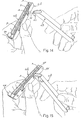
- Figs.1, 2, 3 and 4 show geometrical views of a pair of razor handles matched with each other;
- Figs.5, 6 and 7 show, similarly to Fig.1, the two handles, but being separated between them, and in addition two end views according to VI-VI and VII-VII of Fig.5;
- Figs.8 and 9 show views of the two handles from the face of them destined to the matching;
- Figs.10, 11 and 12 show separately a possible type of head able to be received in a handle as illustrated in the preceding Figures;
- Fig.13 shows in enlarged cross section the handle with a head seat and a head engaged therein;
- Figs.14, 15, 16 and 17 show steps for the drawing out of a head till to the conditions for the razor use;
- Fig.18 shows a perspective view of a handle which can be used;
- Figs.19 to 26 show an embodiment of the system for the handle engagement with a head, in external view with the handle partially matched, in a section according to XX-XX of Fig.22, in a section according to XXI-XXI of Fig.22, in a view according to XXII-XXII of Fig.19, in section according to XXIII-XXIII of Fig.19, in the views according to XXIV-XXIV and XXV-XXV of Fig.21 and in an end perspective view;
- Figs.27 to 33 show two views of a head, the same head being presented at one handle in two orthogonal views, two orthogonal views of the opposite handle end, and an enlarged cross section view of the handle with the head housed therein;
- Figs.34 to 39 show similarly to Figs.27 to 32 a further embodiment;
- Figs.40 and 41 show similarly to Figs.20, 21 a modified embodiment of them;
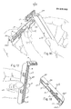
- Figs.42, 43 show in a perspective way two further embodiments of the grip end of a handle;
- Figs.44 to 48 show in a perspective way and in two geometrical views, a head and a handle end, as well as two geometrical views of the other handle end;
- Figs.49 to 53 show in side view two handles in the arrangements for the coupling, two views according to LI-LI of Fig.49 and LII-LII of Fig.50 as well as a view of the head fitted in the handle;
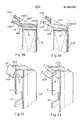
- Figs.54 to 56 show in several views the operations for the removal or the insertion of the head into the handle of Figs.49 to 53;
- Fig.57 shows a general diagram; and
- Figs.58 and 59 show a further construction with one handle only.
- Referring first to Figs.1 to 18, 1A and 1B indicate two razor handles equal between them. Each of these is channel-like developed with a cross section substantially U-shaped and with the sides jointed with
diaphragms seats 7 in each handle. In each seat a shaving head 9 of traditional or particular type may be received. In a central position of the longitudinal dimension of eachseat 7, anotch 12 is provided in the handle wall, which notch results equally spaced between thewall 5 and thewall 4 or respectively 3. Eachnotch 12 has, from the edge of the respective seat, such a depth as to permit one end of a handle to be inserted therethrough for a release engagement of the head 9 received in the same seat, in order to be able to remove it by a sliding parallel to the wings of the U-shaped cross section of the handle. - Each of the
handles diaphragm 4, anappendix 14 for the engagement of the head; said appendix has a suitable shape to engage the head in the grip central point provided therein. Various shapes ofappendices 14 which are illustrated in the drawings will be described hereinafter. - In the example of Figs.1 to 17, like in Fig.42, an
appendix 14 is provided made up of twowings 141 and of a frontsmall wall 142 having two edges parallel between them and transversal to the handle to be engaged in the suitable head seat. At the end opposite to that provided with theappendix 14 three laminar appendices are provided, two outside indicated by 16 and one inside indicated by 17, to cooperate - in the manner described below - to the mutual engagement of the twohandles - The two
handles seats 7 of one of the handles face theseats 7 of the other handle, theseats 7 thus resulting mutually covered and closed. The relative engagement between the twohandles plate 142 of theappendix 14 of one handle and of the inside laminar appendix of the other handle, both having step-profile for release cooperating. The engagement and disengagement easily take place through a relative sliding and the release overcoming of a limited resistance to the elastic deformation; the engagement and disengagement - according to the construction - may be carried out by relative longitudinal sliding between the two handles being put in contact along the seat openings edges, respectively by relative approach and moving away in a direction perpendicular or inclined to the longitudinal handle orientation. - Upon matching, the two
handles notches 12 which match to each other thus defining (see Fig.4) two small windows through which it is possible to control also the presence of the shaving heads. - A shaving head 9 may be suitably retained with a limited effect of restraint in the
respective seat 7 either by a simple friction resistance or, possibly, by a proper shape of at least one of the inside walls of the seat, which cooperates with a corresponding shaping of the head - as can be seen in Fig.13 by way of example - to obtain an interference which can be overcome by a limited effort. - By examining Figs.1 to 5 and Figs.14 to 17 it will be apparent that in the matching situation the two handles make up a compact and substantially closed package comprising two handles and four heads (Figs.1 to 4). By disconnecting the two
handles handle 1B, one of the heads housed in theseat 7 of theother handle 1A, can be drawn out: by inserting theappendix 14 into the corresponding notch 12 (Figs.14, 15); by engaging thesame appendix 14 into the housing provided in the head 9 (this housing being located in correspondence of notch 12); and then by forcing - according to arrow f15 of Fig.15 - thehandle 1B towards thehandle 1A to uproot the head 9 engaged by thehandle 1B and thus drawing out said head 9 (Fig.16) engaged by thehandle 1B. Thus, the razor made up ofpieces 1B and 9 is ready for use, thehandle 1A resulting temporarily unused. The razor use is possible by a handle which retains in its seats heads which are not in use and new or even utilized to be thrown away together with the handle after the exhaustion of handles and heads store represented by the two handles and four heads shown in Figs.1 to 4. It is not excluded, however, that the assembly of Figs.1 to 4 might be supplied with further spare heads. In any case, the pair ofhandles - A modified form of the grip and engagement appendix of the head (respect to the construction illustrated in Figs.1 to 18 and 42) is shown in Fig.43 where, adjacent to the
transversal diaphragm 4, theappendix 14 is developed by two fork-shaped wings 143 forming twoopposite edges 144 which may resiliently approach to each other by a flexion of the material the twowings 143 are made of; this allows the elastic deformations to be transferred to the handle, which deformations are demanded from the head material in the preceding solution. - A further embodiment of the grip and restraint appendix of the head is shown in Figs.19 to 26, in which the
appendix 14 is elastically deformable in its shape. In this construction, twowings 145 are jointed by aplate 16 which makes up one of the two grip edges. Theother grip edge 147 is made up of alever member 148, which is located in intermediate position between the twowings 145 and is jointed to thetransversal diaphragm 4 by a fulcrum-heel 148A of such dimensions as to consent an easy deformation when acting on theend 148B of thelever member 148 according to arrow f148. In this construction a shaping of the inside surfaces ofwings 161 of theend 16 and of the outside surfaces ofwings 145 with projections and impressions designated by 162 and 145A, may be provided to ensure the mutual restraint between the two handles (Figs.19 and 20); in this case, instead of anintermediate wall 17, a cover-like profiling 171 is provided able to cover theelastic edges cooperating shapings - In Figs.40 and 41 a modified construction, respect to the one previously illustrated, of the grip and
restraint appendix 14 is shown. The modification is substantially represented - respect to the construction of Figs.19 to 26 - by the fact that thewings 145, together withplate 146, form a support for thelever 148 which carries theedge 147 and is engaged - instead by a fulcrum 149A - by anelastic fulcrum 148C rising fromplate 146 rather than fromdiaphragm 4. - The construction of Figs.27 to 33 provides for the use of a
particular head 91 of a different type being already on the market; in this case, each one ofhandles grip appendix 214, shaped as shown in the drawing for the engagement in the channel formed by thehead 91, with mutual yielding of sides and edges. A correspondent shaping ofends 216 is to cooperate with theappendix 214 for the mutual restraint betweenhandles - Figs.34 to 39 show a construction for the use of
heads 92 derived from traditional razors. In this case, eachhandle engagement appendix 314 with two side by sidesymmetrical wings 314A which are elastically yieldable to penetrate in a release or forced way in corresponding seats of the head in order to retain it. In this construction, the opposite end of each handle is shaped as shown at 316 (Figs.38 and 39) with two wings apt to flank theappendix 314 by engaging therewith through reliefs and depressions-type shapings in a similar manner as has been provided with reference to Figs.19 and 20. - In Figs.44 and 48 there is shown a further modified construction of the
handles heads 94 of a different type. In this case the grip and restraint appendix of the head is developed with a pair ofprojections 414, able to penetrate with some shrinkage in corresponding seats of the head. The opposite end of each handle is shaped as shown at 416 (Figs.47 and 48) in order to cooperate withprojections 414 so that to complete the package formed by two equal and opposite connected handles. - In the construction of Figs.49 to 54 a modification is shown of the handles indicated by 101A and 101B which are, however, shaped with
appendices 514 and 516 analogous to those 414 and 416. In this construction, the handles present twoseats 70 which no longer open sideways with the handle U-shape cross section, but they open at the ends; accordingly, in this construction, the heads are not inserted into and drawn out with a movement transversal to the handles extension, but with a sliding in the longitudinal direction. In this case, instead ofnotches 12,longitudinal slots 112 are provided, which rise from the end edges of the handles where theseats 70 open being developed as a longitudinal well with a single transversal intermediate diaphragm 505. The drawing out of ahead 95 is obtained by inserting theshaped end 514 into theslot 112 and by longitudinally sliding the razor package thus formed along theslot 112 itself for the removal. - In the summarizing diagram of Fig.57, it is intended that one handle may receive heads in seats which open according to different directions as indicated by the various arrows, that is, according to both longitudinal (FX) and transversal (FY and FZ) directions, according to opposite orientations and according to two pairs orientations at right angle to each other. The dispositions may be alternative or even accumulative; in the latter case a handle construction can be obtained having a plurality of seats and representing therefore a package for the same number of heads. In this case, a protective and enclosing envelope will have possibly to be provided.
- In Figs.58 and 59 a
handle 101 is provided, which has two or even threeseats 107 to receive the same number of heads, and which is closed by acap 601; this cap engages - with suitable shapings - the heads which fit into theseats 107. The cap, developed as a razor handle, cooperates substantially with a housing forming head seats which housing, in turn, may not be shaped as a razor handle. - It should be understood that the drawing shows an exemplification given only as a practical demonstration of the invention, as this invention may vary in the forms and dispositions without nevertheless coming out from the idea on which the same invention is based.
Claims (10)
Priority Applications (1)
| Application Number | Priority Date | Filing Date | Title |
|---|---|---|---|
| AT85830009T ATE37681T1 (en) | 1984-01-24 | 1985-01-17 | WET RAZOR WITH HANDLE HOLDING A SPARE HEAD. |
Applications Claiming Priority (2)
| Application Number | Priority Date | Filing Date | Title |
|---|---|---|---|
| IT09317/84A IT1198766B (en) | 1984-01-24 | 1984-01-24 | WET SHAVING COMPLEX WITH FORMING HANDLE SEATS FOR SHAVING HEADS |
| IT931784 | 1984-01-24 |
Publications (3)
| Publication Number | Publication Date |
|---|---|
| EP0150160A2 true EP0150160A2 (en) | 1985-07-31 |
| EP0150160A3 EP0150160A3 (en) | 1986-05-28 |
| EP0150160B1 EP0150160B1 (en) | 1988-10-05 |
Family
ID=11128349
Family Applications (1)
| Application Number | Title | Priority Date | Filing Date |
|---|---|---|---|
| EP85830009A Expired EP0150160B1 (en) | 1984-01-24 | 1985-01-17 | Wet-shaving unit with handle forming seats for shaving heads |
Country Status (7)
| Country | Link |
|---|---|
| US (2) | US4612704A (en) |
| EP (1) | EP0150160B1 (en) |
| JP (1) | JPH0687909B2 (en) |
| AT (1) | ATE37681T1 (en) |
| AU (1) | AU580068B2 (en) |
| DE (1) | DE3565377D1 (en) |
| IT (1) | IT1198766B (en) |
Cited By (5)
| Publication number | Priority date | Publication date | Assignee | Title |
|---|---|---|---|---|
| WO1987000113A1 (en) * | 1985-07-04 | 1987-01-15 | Synertrade & Finance S.A. | Razing set |
| FR2602451A1 (en) * | 1986-08-07 | 1988-02-12 | America Israel Blades Ltd | DISPOSABLE SAFETY RAZOR |
| GB2245859A (en) * | 1990-07-10 | 1992-01-15 | Gou Wen Di | Razor |
| EP0619771A1 (en) * | 1992-10-08 | 1994-10-19 | The Gillette Company | Fixed head disposable razor |
| WO1995010398A1 (en) * | 1993-10-15 | 1995-04-20 | Warner-Lambert Company | Disposable razor with removable razor head |
Families Citing this family (8)
| Publication number | Priority date | Publication date | Assignee | Title |
|---|---|---|---|---|
| US4756082A (en) * | 1987-05-12 | 1988-07-12 | Apprille Jr Domenic V | Razor blade assembly and handle therefor |
| US4833779A (en) * | 1987-06-30 | 1989-05-30 | American Safety Razor Company | Platform, handle and shield for safety razor |
| JPH0610947Y2 (en) * | 1988-10-13 | 1994-03-23 | 株式会社アンノ・オフィス | Razor |
| US5265759A (en) * | 1990-08-02 | 1993-11-30 | Wilkinson Sword Gesellschaft Mit Beschrankter Haftung | Arrangement for the accommodation and sales display of razor blade units of wet razors packaged in dispensers |
| DE9011304U1 (en) * | 1990-08-02 | 1991-12-05 | Wilkinson Sword Gmbh, 5650 Solingen, De | |
| KR0120873Y1 (en) * | 1995-08-23 | 1998-07-15 | 이종철 | Portable toothbrush with shaving device |
| US20090007443A1 (en) * | 2007-07-06 | 2009-01-08 | Cuocolo Jr Joseph M | Personal Razor Device |
| DE102022120574A1 (en) * | 2022-08-16 | 2024-02-22 | PAPACKS SALES GmbH | razor |
Citations (4)
| Publication number | Priority date | Publication date | Assignee | Title |
|---|---|---|---|---|
| DE2203235A1 (en) * | 1972-01-24 | 1973-08-02 | Ernst R Herold | RAZOR |
| US4182031A (en) * | 1978-02-10 | 1980-01-08 | Cecil John Jr | Razor with handle to store a blade unit or cartridge |
| US4272886A (en) * | 1978-03-28 | 1981-06-16 | Kai Cutlery Center Co., Ltd. | Shaver unit |
| GB2100646A (en) * | 1981-06-22 | 1983-01-06 | Gillette Co | Safety razors. |
Family Cites Families (8)
| Publication number | Priority date | Publication date | Assignee | Title |
|---|---|---|---|---|
| US1548164A (en) * | 1924-01-30 | 1925-08-04 | Charles S Parker | Handle for safety razors and the like |
| GB1113045A (en) * | 1965-09-09 | 1968-05-08 | Gillette Industries Ltd | Improvements relating to safety razor blades |
| US3783493A (en) * | 1971-10-22 | 1974-01-08 | Warner Lambert Co | Method for dispensing razor blade cartridges |
| US3967375A (en) * | 1973-02-26 | 1976-07-06 | Hoffschmidt Edward J | Razor construction |
| BR8003189A (en) * | 1979-05-25 | 1980-12-30 | Gillette Co | DISPOSABLE SHAVING APPLIANCE |
| GB2101091B (en) * | 1981-06-19 | 1984-12-19 | Gillette Co | Protective razor package |
| US4461078A (en) * | 1982-02-01 | 1984-07-24 | Carreker Reginald V | Styling razor |
| GB8406683D0 (en) * | 1984-03-14 | 1984-04-18 | Wilkinson Sword Ltd | Razor system |
-
1984
- 1984-01-24 IT IT09317/84A patent/IT1198766B/en active
- 1984-12-28 US US06/687,267 patent/US4612704A/en not_active Ceased
- 1984-12-28 JP JP59275049A patent/JPH0687909B2/en not_active Expired - Lifetime
-
1985
- 1985-01-17 EP EP85830009A patent/EP0150160B1/en not_active Expired
- 1985-01-17 AT AT85830009T patent/ATE37681T1/en active
- 1985-01-17 DE DE8585830009T patent/DE3565377D1/en not_active Expired
- 1985-06-18 AU AU43804/85A patent/AU580068B2/en not_active Ceased
-
1988
- 1988-09-23 US US07/248,439 patent/USRE33432E/en not_active Expired - Lifetime
Patent Citations (4)
| Publication number | Priority date | Publication date | Assignee | Title |
|---|---|---|---|---|
| DE2203235A1 (en) * | 1972-01-24 | 1973-08-02 | Ernst R Herold | RAZOR |
| US4182031A (en) * | 1978-02-10 | 1980-01-08 | Cecil John Jr | Razor with handle to store a blade unit or cartridge |
| US4272886A (en) * | 1978-03-28 | 1981-06-16 | Kai Cutlery Center Co., Ltd. | Shaver unit |
| GB2100646A (en) * | 1981-06-22 | 1983-01-06 | Gillette Co | Safety razors. |
Cited By (10)
| Publication number | Priority date | Publication date | Assignee | Title |
|---|---|---|---|---|
| WO1987000113A1 (en) * | 1985-07-04 | 1987-01-15 | Synertrade & Finance S.A. | Razing set |
| US4831729A (en) * | 1985-07-04 | 1989-05-23 | Roland Beuchat | Razor set |
| FR2602451A1 (en) * | 1986-08-07 | 1988-02-12 | America Israel Blades Ltd | DISPOSABLE SAFETY RAZOR |
| GB2245859A (en) * | 1990-07-10 | 1992-01-15 | Gou Wen Di | Razor |
| EP0619771A1 (en) * | 1992-10-08 | 1994-10-19 | The Gillette Company | Fixed head disposable razor |
| EP0619771A4 (en) * | 1992-10-08 | 1995-05-31 | Gillette Co | Fixed head disposable razor. |
| WO1995010398A1 (en) * | 1993-10-15 | 1995-04-20 | Warner-Lambert Company | Disposable razor with removable razor head |
| BE1008362A3 (en) * | 1993-10-15 | 1996-04-02 | Warner Lambert Co | Disposable razor shaving head removable. |
| US6026577A (en) * | 1993-10-15 | 2000-02-22 | Warner-Lambert Company | Disposable razor with removable razor head |
| US6317990B1 (en) | 1993-10-15 | 2001-11-20 | Warner-Lambert Company | Disposable razor with removable razor head |
Also Published As
| Publication number | Publication date |
|---|---|
| AU580068B2 (en) | 1988-12-22 |
| DE3565377D1 (en) | 1988-11-10 |
| IT8409317A0 (en) | 1984-01-24 |
| EP0150160B1 (en) | 1988-10-05 |
| EP0150160A3 (en) | 1986-05-28 |
| IT1198766B (en) | 1988-12-21 |
| JPH0687909B2 (en) | 1994-11-09 |
| JPS60163682A (en) | 1985-08-26 |
| ATE37681T1 (en) | 1988-10-15 |
| US4612704A (en) | 1986-09-23 |
| AU4380485A (en) | 1986-12-24 |
| USRE33432E (en) | 1990-11-13 |
Similar Documents
| Publication | Publication Date | Title |
|---|---|---|
| EP0150160A2 (en) | Wet-shaving unit with handle forming seats for shaving heads | |
| US5407066A (en) | Packing unit | |
| US4389773A (en) | Shaving implement | |
| US5285577A (en) | Letter opener with protected recess for business card and removable slide-in cover | |
| US4136470A (en) | Quick change picture frame | |
| US5598924A (en) | Spanner holder | |
| JP2521827Y2 (en) | Knife with replaceable blade | |
| US5410810A (en) | Safety razors | |
| US3878605A (en) | Handle construction | |
| US2794246A (en) | Disposable razor | |
| HU223282B1 (en) | Shaving system and method, changeable razor cartridge and razor handle applied therein and method for making the same | |
| GB2179622A (en) | A package for scissors | |
| US3353573A (en) | Portable power tool | |
| US3951263A (en) | Holders for needles, pins and like articles | |
| JPH0632002Y2 (en) | Compact container | |
| US4562645A (en) | Razor cartridge and method of manufacture | |
| US1957065A (en) | Razor sheath | |
| JP3275092B2 (en) | Razor unit | |
| EP0010379B1 (en) | A re-usable, cylindrical transparent coinholder for holding a predetermined number of coins | |
| US2070002A (en) | Window badge | |
| CN211870204U (en) | Plastic packing belt convenient to recycle | |
| JP2764344B2 (en) | Replaceable blade container for replaceable blades | |
| EP0744854A1 (en) | Device for accommodating and retaining utensils, tools, instruments, and the like | |
| JP2596856Y2 (en) | Blade spare type cutter knife holder | |
| JPS6137409Y2 (en) |
Legal Events
| Date | Code | Title | Description |
|---|---|---|---|
| PUAI | Public reference made under article 153(3) epc to a published international application that has entered the european phase |
Free format text: ORIGINAL CODE: 0009012 |
|
| AK | Designated contracting states |
Designated state(s): AT BE CH DE FR GB LI NL SE |
|
| PUAL | Search report despatched |
Free format text: ORIGINAL CODE: 0009013 |
|
| AK | Designated contracting states |
Kind code of ref document: A3 Designated state(s): AT BE CH DE FR GB LI NL SE |
|
| 17P | Request for examination filed |
Effective date: 19860614 |
|
| 17Q | First examination report despatched |
Effective date: 19870803 |
|
| GRAA | (expected) grant |
Free format text: ORIGINAL CODE: 0009210 |
|
| AK | Designated contracting states |
Kind code of ref document: B1 Designated state(s): AT BE CH DE FR GB LI NL SE |
|
| REF | Corresponds to: |
Ref document number: 37681 Country of ref document: AT Date of ref document: 19881015 Kind code of ref document: T |
|
| REF | Corresponds to: |
Ref document number: 3565377 Country of ref document: DE Date of ref document: 19881110 |
|
| PGFP | Annual fee paid to national office [announced via postgrant information from national office to epo] |
Ref country code: SE Payment date: 19890126 Year of fee payment: 5 |
|
| ET | Fr: translation filed | ||
| PGFP | Annual fee paid to national office [announced via postgrant information from national office to epo] |
Ref country code: FR Payment date: 19890130 Year of fee payment: 5 Ref country code: AT Payment date: 19890130 Year of fee payment: 5 |
|
| PGFP | Annual fee paid to national office [announced via postgrant information from national office to epo] |
Ref country code: NL Payment date: 19890131 Year of fee payment: 5 |
|
| PGFP | Annual fee paid to national office [announced via postgrant information from national office to epo] |
Ref country code: BE Payment date: 19890209 Year of fee payment: 5 |
|
| PLBE | No opposition filed within time limit |
Free format text: ORIGINAL CODE: 0009261 |
|
| STAA | Information on the status of an ep patent application or granted ep patent |
Free format text: STATUS: NO OPPOSITION FILED WITHIN TIME LIMIT |
|
| 26N | No opposition filed | ||
| PG25 | Lapsed in a contracting state [announced via postgrant information from national office to epo] |
Ref country code: AT Effective date: 19900117 |
|
| PG25 | Lapsed in a contracting state [announced via postgrant information from national office to epo] |
Ref country code: SE Effective date: 19900118 |
|
| PG25 | Lapsed in a contracting state [announced via postgrant information from national office to epo] |
Ref country code: BE Effective date: 19900131 |
|
| BERE | Be: lapsed |
Owner name: BERRETTI GIORGIO Effective date: 19900131 |
|
| PG25 | Lapsed in a contracting state [announced via postgrant information from national office to epo] |
Ref country code: NL Effective date: 19900801 |
|
| GBPC | Gb: european patent ceased through non-payment of renewal fee | ||
| NLV4 | Nl: lapsed or anulled due to non-payment of the annual fee | ||
| PG25 | Lapsed in a contracting state [announced via postgrant information from national office to epo] |
Ref country code: FR Effective date: 19900928 |
|
| REG | Reference to a national code |
Ref country code: CH Ref legal event code: PL |
|
| REG | Reference to a national code |
Ref country code: FR Ref legal event code: ST |
|
| REG | Reference to a national code |
Ref country code: FR Ref legal event code: TP |
|
| REG | Reference to a national code |
Ref country code: FR Ref legal event code: AR |
|
| REG | Reference to a national code |
Ref country code: GB Ref legal event code: 728C |
|
| REG | Reference to a national code |
Ref country code: CH Ref legal event code: PUE Owner name: JAMIE DARDER TRANSFER- INNERVISION INC. |
|
| REG | Reference to a national code |
Ref country code: FR Ref legal event code: DE |
|
| REG | Reference to a national code |
Ref country code: GB Ref legal event code: 732E Ref country code: GB Ref legal event code: 728A |
|
| EUG | Se: european patent has lapsed |
Ref document number: 85830009.8 Effective date: 19901107 |
|
| PGFP | Annual fee paid to national office [announced via postgrant information from national office to epo] |
Ref country code: CH Payment date: 19981228 Year of fee payment: 15 |
|
| PG25 | Lapsed in a contracting state [announced via postgrant information from national office to epo] |
Ref country code: LI Free format text: LAPSE BECAUSE OF NON-PAYMENT OF DUE FEES Effective date: 20000131 Ref country code: CH Free format text: LAPSE BECAUSE OF NON-PAYMENT OF DUE FEES Effective date: 20000131 |
|
| REG | Reference to a national code |
Ref country code: CH Ref legal event code: PL |
|
| PGFP | Annual fee paid to national office [announced via postgrant information from national office to epo] |
Ref country code: DE Payment date: 20010803 Year of fee payment: 17 |
|
| REG | Reference to a national code |
Ref country code: GB Ref legal event code: IF02 |
|
| PG25 | Lapsed in a contracting state [announced via postgrant information from national office to epo] |
Ref country code: DE Free format text: LAPSE BECAUSE OF NON-PAYMENT OF DUE FEES Effective date: 20020801 |
|
| PGFP | Annual fee paid to national office [announced via postgrant information from national office to epo] |
Ref country code: GB Payment date: 20040107 Year of fee payment: 20 |
|
| PG25 | Lapsed in a contracting state [announced via postgrant information from national office to epo] |
Ref country code: GB Free format text: LAPSE BECAUSE OF EXPIRATION OF PROTECTION Effective date: 20050116 |
|
| REG | Reference to a national code |
Ref country code: GB Ref legal event code: PE20 |