EP0149947A2 - Gasdüsenantrieb für lenkbare Rakete - Google Patents
Gasdüsenantrieb für lenkbare Rakete Download PDFInfo
- Publication number
- EP0149947A2 EP0149947A2 EP84402737A EP84402737A EP0149947A2 EP 0149947 A2 EP0149947 A2 EP 0149947A2 EP 84402737 A EP84402737 A EP 84402737A EP 84402737 A EP84402737 A EP 84402737A EP 0149947 A2 EP0149947 A2 EP 0149947A2
- Authority
- EP
- European Patent Office
- Prior art keywords
- nozzles
- valves
- propellant
- gas
- projectile
- Prior art date
- Legal status (The legal status is an assumption and is not a legal conclusion. Google has not performed a legal analysis and makes no representation as to the accuracy of the status listed.)
- Granted
Links
Images


Classifications
-
- F—MECHANICAL ENGINEERING; LIGHTING; HEATING; WEAPONS; BLASTING
- F42—AMMUNITION; BLASTING
- F42B—EXPLOSIVE CHARGES, e.g. FOR BLASTING, FIREWORKS, AMMUNITION
- F42B10/00—Means for influencing, e.g. improving, the aerodynamic properties of projectiles or missiles; Arrangements on projectiles or missiles for stabilising, steering, range-reducing, range-increasing or fall-retarding
- F42B10/60—Steering arrangements
- F42B10/66—Steering by varying intensity or direction of thrust
- F42B10/663—Steering by varying intensity or direction of thrust using a plurality of transversally acting auxiliary nozzles, which are opened or closed by valves
-
- F—MECHANICAL ENGINEERING; LIGHTING; HEATING; WEAPONS; BLASTING
- F02—COMBUSTION ENGINES; HOT-GAS OR COMBUSTION-PRODUCT ENGINE PLANTS
- F02K—JET-PROPULSION PLANTS
- F02K9/00—Rocket-engine plants, i.e. plants carrying both fuel and oxidant therefor; Control thereof
- F02K9/80—Rocket-engine plants, i.e. plants carrying both fuel and oxidant therefor; Control thereof characterised by thrust or thrust vector control
- F02K9/805—Rocket-engine plants, i.e. plants carrying both fuel and oxidant therefor; Control thereof characterised by thrust or thrust vector control servo-mechanisms or control devices therefor
-
- F—MECHANICAL ENGINEERING; LIGHTING; HEATING; WEAPONS; BLASTING
- F02—COMBUSTION ENGINES; HOT-GAS OR COMBUSTION-PRODUCT ENGINE PLANTS
- F02K—JET-PROPULSION PLANTS
- F02K9/00—Rocket-engine plants, i.e. plants carrying both fuel and oxidant therefor; Control thereof
- F02K9/80—Rocket-engine plants, i.e. plants carrying both fuel and oxidant therefor; Control thereof characterised by thrust or thrust vector control
- F02K9/90—Rocket-engine plants, i.e. plants carrying both fuel and oxidant therefor; Control thereof characterised by thrust or thrust vector control using deflectors
Definitions
- the present invention relates to guided projectiles and it relates to a gas propellant using a solid propellant and comprising a plurality of nozzles whose relative flow rate can be varied to modify the flight path of the projectile.
- Solid propellant propellants have already been proposed to provide two mutually orthogonal force components: a longitudinal thrust force of fixed size and a lateral thrust force controlled in size and direction.
- Solid propellant guide thrusters can be divided into two distinct classes, depending on the operating mode of the means for controlling the relative flow rate of the gas jets from the nozzles.
- a first class as described in American patent no . 4,017,040, each pair of diametrically opposed nozzles is equipped with a valve having three stable positions: a first and a second position for which the gas flow is directed in one and the other nozzles and a third position for which the gas flow is equally distributed between the two nozzles.
- the second class illustrated by the device described in French patent application No.
- each pair of nozzles is equipped with a valve having two stable positions and operating according to an alternating cycle "all or nothing ".
- the valve opening duty cycle By varying the valve opening duty cycle, the gas flow can be distributed on demand between the two diametrically opposite nozzles.
- the prior art gas propellants do not make it possible to satisfactorily respond to the problem posed by the design of a gas propellant for a guided projectile.
- the object of the invention is to provide a gas propellant whose operating regimes differ depending on whether the projectile is in the cruising phase of its trajectory or in the terminal guide phase on the target.
- the object of the invention is a gas propellant for a guided projectile, having at least one pair of diametrically opposite side nozzles to create thrust forces inclined towards the rear of the projectile.
- This projectile includes a solid propellant bar, relatively insensitive to the combustion pressure, which is arranged in a combustion chamber is coupled to the side nozzles, and valves having two stable positions which are controlled by control circuits making it possible to inhibit the state corresponding to the simultaneous closing of two nozzles of the same pair.
- valves of a pair of nozzles are coupled by mechanical safety means. to compensate for damage to the valves or their control circuits, in order to avoid inadvertent explosion of the propellant.
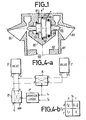
- Figure 1 relates to the prior art and shows in a longitudinal sectional view a gas propellant in which is included a valve with three stable positions.
- This propellant 100 is constituted by a hollow cylindrical body 101 which encloses a block 102 of a solid propellant and at the end of this body are arranged two pairs of diametrically opposite nozzles, of which only one pair is shown in the figure.
- the relative flow rate of the gas escaping through the opposite nozzles 103 and 104 is controlled by a pneumatic valve 105 of cylindrical shape and this valve can occupy three stable positions.
- the valve comprises, in its middle part, three adjacent cyclindrical segments of different sections: a segment 106 of small section and a segment 107 of medium section, which are arranged on either side of a segment 108 of stronger section.
- the tightness of each of these segments is ensured by circular seals 109 arranged in corresponding grooves located in the body 110 of the valve.
- a first orifice 111 Opposite the faces of the middle segment 108 of larger cross section are disposed a first orifice 111 which receives a control pressure and a second orifice 112 which opens to the outside.
- valve 105 When the control pressure applied to the orifice 111 at a zero value, the valve 105 closes the inlet opening of the nozzle 104, and conversely when this control pressure at a maximum value the valve closes the opening of inlet of the nozzle 103.
- the valve can occupy a central position for which the flow of gas from the generator is equally distributed between the two nozzles.
- Figure 2 also relates to the prior art and shows, in a sectional view a gas propellant in which is included a valve with two stable positions. Only the section of the propellant comprising the nozzles and the means for controlling the gas flow has been shown.
- This cylindrical section comprises a body in which is disposed at least one pair of diametrically opposite nozzles 202 and 203. These nozzles are coupled to the gas generator by independent gas conduits 204 and 205, the center distance of which is at a determined value L.
- a sliding bar 206 makes it possible to alternately close the gas conduits of the nozzles. This sliding bar is equipped with two pneumatic cylinders 207 and 208 which can occupy two extreme positions, the total stroke of these cylinders is equal to the width 1 of the gas conduits.
- These jacks have inlet-outlet orifices 207a, 207b and 208a, 208b which are connected two by two in parallel and receive a pneumatic control signal which is applied to their respective inputs 209 and 210.
- This control signal is a cyclic signal in channels with a relatively high cycle frequency. If the opening duty cycle (RCO) of the gas pipes is varied, the relative flow rate of the gas flow passing through the nozzles can be adjusted. So when the value of the RCO is equal to half, the gas flows are equally distributed in the two opposite nozzles.
- RCO opening duty cycle
- Figure 3 is a partial sectional view showing a form of construction of a gas propellant according to the invention.
- the body 2 of the propellant 1 is of cylindrical shape, and its axis of revolution, or longitudinal axis X, is oriented towards the front of the projectile.
- the gas generator 3 consists of a solid propellant bar, which is placed in a combustion chamber adjacent to the nozzle block 4. The gas generator is not part of the invention and its construction will not be described since it is widely known per se.
- the nozzle block 4 comprises at least one pair of diametrically opposite nozzles T i , T 2 , but more generally, it comprises two pairs of mutually orthogonal nozzles as 11 will be described later.
- the nozzles are located at the periphery of the thruster body and suitably tilted to create thrust forces directed toward the rear of the projectile. It follows that the ratio of the respective quantities of the longitudinal components P L and transverse P T are perfectly known.
- the nozzles of the convergent-divergent type comprise a nozzle throat 5,6 for example, of rectangular section of width 1 and height h, and the inter-axis of these nozzle throats at a value L.
- valves 7 and 8 Opposite the necks of nozzles are arranged valves 7 and 8 for opening-closing the nozzles.
- a valve is constituted by a sliding vane 9 or 10, and the section of the vane is equal to that of the nozzle neck.
- the movements of the pallet are ensured by a pneumatic actuator comprising a piston 11 or 12 and a sealed cavity 13 or 14 provided with two inlet / outlet orifices E 1 , E l and E 2 , E 2 which are located on either side of the piston.
- the pallet stroke can be set to value 1 corresponding to the width of the nozzle, it follows that each of the nozzles can be completely open or closed.
- the actuator cavity input / output ports are connected to electro-pneumatic control circuits to control the position of the valve vanes.
- the vane 9 closes the nozzle neck.
- the vane 9 is retracted and the nozzle neck is free.
- the operation of the valve 8 is identical to that of the valve 7 as described above. The positioning of valves 7 and 8 must not be independent and the simultaneous sealing of the two nozzle necks must be inhibited.
- FIG. 4a schematically represents an embodiment of the control circuits of the closing-opening valves of the nozzles.
- a gas source G for example, that supplied by the propellant, is connected to the inlet 1 of a first pneumatic permutator 15 whose inlet 2 is connected to a leak path.
- the outputs of this permutator pneumatic are connected to two gas conduits which are connected directly to the valve 8 of the nozzle T 2 and, indirectly, via a second pneumatic permutator 16 to the valve 7 of the nozzle T 1 .
- the function of the second permutator 16 is in a first state of connecting the orifices E 1 and E 2 , E 1 and E 2 of inlet / outlet of the valves so that the vanes of the valves can be moved in the same direction, and in a second state to cross the connections between the valves so that the vanes can be moved in opposite directions.
- the function of the first permutator 15 is to reverse the directions of movement of the valve vanes.
- the control input 5 of the second permutator 16 receives a first control signal S 1 with two states and the control input 5 of the first permutator 15 receives the control signal S 1 and a second control signal S 2 with two states , via a logical operator 17 whose truth table is given in FIG. 4b and indicates the states of opening of the nozzles T 1 and T 2 .
- the function of this logical operator is to prohibit the state corresponding to the simultaneous closure of the nozzles T 1 and T 2 .
- FIG. 3 is symbolically represented by a circle 20 a safety means making it possible to compensate for the damage to the valves, but also a damage to the control circuits of these valves.
- This safety means consists of a "coupling" of the valve pallets which allows that the distance between the ends of the pallets 9 and 10 cannot in any case exceed the value L corresponding to the center of axis of the nozzle necks.
- FIG. 5a represents a first embodiment of the safety means 20.
- the opposite ends of the vanes 9a and 10a of the valves each include a cavity 21a and 22b in which is engaged a connecting rod 20a provided with stopper 23a and 24a.
- FIG. 5b represents a variant construction of the security means 20 described in FIG. 5a.
- one of the opposite ends of the pallets 9b or 10b comprises a cavity 21b in which engages a rod 20b secured to the opposite pallet 10b; this rod being provided with a stop stop 23b.
- This pallet coupling device constitutes a retractable mechanical coupling.
- FIG. 6a represents a second mode of construction of the safety means 20.
- the opposite ends of the sliding vanes 9c and 10c of the valves have stop hooks 24a and 24b, which feel arranged in the plane of the smallest dimension g of the pallets. These stop hooks overlap each other in order to limit the relative movements of the pallets.
- FIG. 6b represents a variant construction of the security means described in FIG. 6a.
- This construction variant consists in placing the stop hooks 25a and 25b in the larger dimension plane h of the sliding vanes 9d and 10d of the valves.
- the relative displacements of the ends of the sliding pallets which are located in the pipe necks are limited to the value L corresponding to the center distance of the nozzle necks and to the value (L-1).
- the stops of the pallets can be provided by auxiliary means arranged on the faces of the pallets.
- the gas flow passage section therefore varies between the value (lh) when one of the nozzles is closed and the value 2 (1.h) when the two nozzles are open.
- the combustion pressure P c of the solid propellant of the gas generator drops when the two nozzle necks are opened together. This drop in combustion pressure must not cause the propellant to go out, to do this a composite propellant that is less sensitive to the combustion pressure than conventional propellants is used.
- FIG. 7 is a sectional view of the nozzle block which represents the arrangement of the opening-closing valves of a gas thruster having two pairs of mutually orthogonal nozzles to ensure the piloting of the projectile guided in two planes perpendicular to each other .
- FIG. 7 only the sliding pallet 50 of one of the valves can be seen, the piston 51 of the corresponding pneumatic actuator and one of the inlet / outlet orifices E 3 .
- FIG. 7 also illustrates an embodiment of the stops for the sliding pallets of the opening-closing valves of the nozzle necks.
- a stopper is constituted by a lug 19a disposed on one of the faces of the pallet; this lug engages in a correctly dimensioned cavity 19b to limit the travel of the sliding pallet to the value 1 corresponding to the width of the nozzle neck.
- the position of the nozzle valves can be moved depending on the physical shape of the nozzles; pneumatic actuators can be replaced by hydraulic and possibly electrical actuators.
- the gas propellant finds its application in guided projectiles which are propelled during the cruise phase of their trajectory.
Landscapes
- Engineering & Computer Science (AREA)
- General Engineering & Computer Science (AREA)
- Chemical & Material Sciences (AREA)
- Combustion & Propulsion (AREA)
- Mechanical Engineering (AREA)
- Fluid Mechanics (AREA)
- Physics & Mathematics (AREA)
- Nozzles (AREA)
- Aiming, Guidance, Guns With A Light Source, Armor, Camouflage, And Targets (AREA)
- Air Bags (AREA)
- Transition And Organic Metals Composition Catalysts For Addition Polymerization (AREA)
- Fluid-Pressure Circuits (AREA)
- Control Of Position, Course, Altitude, Or Attitude Of Moving Bodies (AREA)
Priority Applications (1)
| Application Number | Priority Date | Filing Date | Title |
|---|---|---|---|
| AT84402737T ATE32260T1 (de) | 1984-01-06 | 1984-12-27 | Gasduesenantrieb fuer lenkbare rakete. |
Applications Claiming Priority (2)
| Application Number | Priority Date | Filing Date | Title |
|---|---|---|---|
| FR8400172 | 1984-01-06 | ||
| FR8400172A FR2557926B1 (fr) | 1984-01-06 | 1984-01-06 | Propulseur a gaz pour projectile guide. |
Publications (3)
| Publication Number | Publication Date |
|---|---|
| EP0149947A2 true EP0149947A2 (de) | 1985-07-31 |
| EP0149947A3 EP0149947A3 (en) | 1985-08-28 |
| EP0149947B1 EP0149947B1 (de) | 1988-01-27 |
Family
ID=9299891
Family Applications (1)
| Application Number | Title | Priority Date | Filing Date |
|---|---|---|---|
| EP84402737A Expired EP0149947B1 (de) | 1984-01-06 | 1984-12-27 | Gasdüsenantrieb für lenkbare Rakete |
Country Status (6)
| Country | Link |
|---|---|
| US (1) | US4637572A (de) |
| EP (1) | EP0149947B1 (de) |
| AT (1) | ATE32260T1 (de) |
| CA (1) | CA1244280A (de) |
| DE (1) | DE3469060D1 (de) |
| FR (1) | FR2557926B1 (de) |
Cited By (5)
| Publication number | Priority date | Publication date | Assignee | Title |
|---|---|---|---|---|
| EP0244971A3 (de) * | 1986-05-09 | 1988-04-27 | LUCAS INDUSTRIES public limited company | Steuervorrichtung für Rakete |
| EP0222057A3 (en) * | 1985-08-21 | 1990-03-28 | Rheinmetall Gmbh | Pressure relief valve for a pyrotechnic gas generator |
| EP0489712A3 (en) * | 1988-02-11 | 1993-02-03 | British Aerospace Public Limited Company | Missile steering arrangement using thrust control |
| EP0542606A1 (de) * | 1991-11-15 | 1993-05-19 | Thomson-Brandt Armements | Hydraulisch verriegelter Steuerstrahlregler |
| EP0871582A4 (de) * | 1996-01-03 | 1999-03-24 | Univ Ramot | Vorrichtung und verfahren zum steuern der bewegung eines festkörpers oder einer fluiströmung |
Families Citing this family (14)
| Publication number | Priority date | Publication date | Assignee | Title |
|---|---|---|---|---|
| US5125596A (en) * | 1989-05-23 | 1992-06-30 | Cavalleri Robert J | Fluid shielded movable strut for missile and rocket thrust vector control |
| US5456425A (en) * | 1993-11-04 | 1995-10-10 | Aerojet General Corporation | Multiple pintle nozzle propulsion control system |
| RU2176374C2 (ru) * | 1999-06-10 | 2001-11-27 | Челябинский автоматно-механический завод | Блок газореактивной системы управления |
| RU2154797C1 (ru) * | 1999-06-10 | 2000-08-20 | Челябинский автоматно-механический завод | Блок газореактивной системы управления |
| EP1372186B1 (de) | 2000-10-31 | 2008-12-10 | Sez Ag | Vorrichtung zur Flüssigkeitsbehandlung von scheibenförmigen Gegenständen |
| RU2247305C1 (ru) * | 2003-10-21 | 2005-02-27 | Федеральное Государственное унитарное предприятие "Государственное научно-производственное предприятие "Сплав" | Блок газореактивной системы управления реактивного снаряда |
| RU2383768C1 (ru) * | 2008-08-14 | 2010-03-10 | Открытое акционерное общество "Машиностроительное конструкторское бюро "Искра" имени Ивана Ивановича Картукова" | Управляющий ракетный двигатель твердого топлива |
| RU2382323C1 (ru) * | 2008-11-13 | 2010-02-20 | Федеральное Государственное унитарное предприятие "Государственное научно-производственное предприятие "Сплав" | Блок газоструйной системы управления |
| US8362408B2 (en) * | 2009-10-22 | 2013-01-29 | Honeywell International Inc. | Steerable projectile charging system |
| GB201312593D0 (en) * | 2013-07-13 | 2013-08-28 | Mbda Uk Ltd | A thrust flow powered vehicle |
| US20170096962A1 (en) * | 2015-07-13 | 2017-04-06 | Aerojet Rocketdyne, Inc. | Throat area control system |
| RU2633973C1 (ru) * | 2016-03-17 | 2017-10-20 | Акционерное общество "Корпорация "Московский институт теплотехники" (АО "Корпорация "МИТ") | Ракетный двигатель твердого топлива с однократно изменяемым вектором тяги |
| RU2743670C1 (ru) * | 2020-05-12 | 2021-02-24 | Российская Федерация, от имени которой выступает Министерство обороны Российской Федерации | Ракетный двигатель твёрдого топлива с двумя режимами расхода продуктов сгорания |
| SE2400008A1 (sv) * | 2024-01-16 | 2025-06-24 | Bae Systems Bofors Ab | Basflödesventil för hybridmotor |
Family Cites Families (8)
| Publication number | Priority date | Publication date | Assignee | Title |
|---|---|---|---|---|
| US2974594A (en) * | 1958-08-14 | 1961-03-14 | Boehm Josef | Space vehicle attitude control system |
| US3058489A (en) * | 1959-03-02 | 1962-10-16 | Thompson Ramo Wooldridge Inc | Control for rocket engines |
| US3599899A (en) * | 1969-06-20 | 1971-08-17 | Thiokol Chemical Corp | Rocket control |
| US3721402A (en) * | 1971-06-25 | 1973-03-20 | Us Army | Missile roll control mechanism |
| US4017040A (en) * | 1976-01-12 | 1977-04-12 | The United States Of America As Represented By The Secretary Of The Navy | Steerable extraction rocket |
| FR2386802A1 (fr) * | 1977-04-08 | 1978-11-03 | Thomson Brandt | Dispositif de pilotage pour projectile du genre missile, et projectile equipe de ce dispositif |
| FR2504252B1 (fr) * | 1981-04-21 | 1987-03-06 | Thomson Brandt | Projectile guide |
| FR2538098B1 (fr) * | 1982-12-17 | 1987-11-20 | Thomson Brandt | Dispositif de pilotage par jets de gaz lateraux |
-
1984
- 1984-01-06 FR FR8400172A patent/FR2557926B1/fr not_active Expired
- 1984-12-27 EP EP84402737A patent/EP0149947B1/de not_active Expired
- 1984-12-27 AT AT84402737T patent/ATE32260T1/de not_active IP Right Cessation
- 1984-12-27 DE DE8484402737T patent/DE3469060D1/de not_active Expired
-
1985
- 1985-01-03 US US06/688,638 patent/US4637572A/en not_active Expired - Lifetime
- 1985-01-04 CA CA000471557A patent/CA1244280A/en not_active Expired
Cited By (5)
| Publication number | Priority date | Publication date | Assignee | Title |
|---|---|---|---|---|
| EP0222057A3 (en) * | 1985-08-21 | 1990-03-28 | Rheinmetall Gmbh | Pressure relief valve for a pyrotechnic gas generator |
| EP0244971A3 (de) * | 1986-05-09 | 1988-04-27 | LUCAS INDUSTRIES public limited company | Steuervorrichtung für Rakete |
| EP0489712A3 (en) * | 1988-02-11 | 1993-02-03 | British Aerospace Public Limited Company | Missile steering arrangement using thrust control |
| EP0542606A1 (de) * | 1991-11-15 | 1993-05-19 | Thomson-Brandt Armements | Hydraulisch verriegelter Steuerstrahlregler |
| EP0871582A4 (de) * | 1996-01-03 | 1999-03-24 | Univ Ramot | Vorrichtung und verfahren zum steuern der bewegung eines festkörpers oder einer fluiströmung |
Also Published As
| Publication number | Publication date |
|---|---|
| DE3469060D1 (en) | 1988-03-03 |
| EP0149947B1 (de) | 1988-01-27 |
| FR2557926B1 (fr) | 1986-04-11 |
| FR2557926A1 (fr) | 1985-07-12 |
| EP0149947A3 (en) | 1985-08-28 |
| US4637572A (en) | 1987-01-20 |
| ATE32260T1 (de) | 1988-02-15 |
| CA1244280A (en) | 1988-11-08 |
Similar Documents
| Publication | Publication Date | Title |
|---|---|---|
| EP0149947B1 (de) | Gasdüsenantrieb für lenkbare Rakete | |
| EP0068972B1 (de) | Schubdüsensteuerung für Lenkflugkörper | |
| EP0063979B1 (de) | Gasstrahl-Steuerungsvorrichtung und Projektil mit einer derartigen Vorrichtung | |
| EP0064433B1 (de) | Lenkbarer Flugkörper | |
| CH626167A5 (de) | ||
| EP0447283B1 (de) | Raketensteuerungsanlage mit seitlichem Düsen | |
| FR2659734A1 (fr) | Systeme pour le pilotage d'un missile au moyen de jets gazeux lateraux. | |
| FR2549146A1 (fr) | Ensemble propulsif pour missile statoreacteur a propulseur d'acceleration integre | |
| EP2909571B1 (de) | Kombinierte lenk- und zugreduktionsvorrichtung | |
| EP0112755B1 (de) | Mit seitlich ausströmenden Gasstrahlen arbeitende Steuervorrichtung | |
| EP1045130B1 (de) | Allseitig schwenkbare konvergente - divergente Schubdüse mit einem kardanischen Bedienungsring | |
| EP2143929B1 (de) | Raketentriebwerk umfassend eine Einspritzvorrichtung für Monergol mit modulierbarem Durchfluss und stabiler Einspritzgeschwindigkeit | |
| FR2588372A1 (fr) | Dispositif de pilotage pour projectile guide au moyen de tuyeres laterales | |
| EP1972798B1 (de) | Vorrichtung zur Positionssteuerung eines Stellglieds über ein Servoventil mit Positionsspeicher im Fall einer Panne | |
| EP3271566B1 (de) | Schubumkehrvorrichtung für eine turbostrahl-triebwerksgondel eines flugzeugs | |
| EP0604263B1 (de) | Stellglied zur Bewegung einer schwenkbaren Raketendüse | |
| EP1541833B1 (de) | Gasgenerator sowie mit diesem ausgestattetes Turbostrahltriebwerk für das Anlassen | |
| FR2933743A1 (fr) | Dispositif d'injection de biergol a debit modulable. | |
| EP0152315A1 (de) | Antriebsvorrichtung zur periodischen Schwenkung einer Radarantenne | |
| WO2017072457A1 (fr) | Systéme de pilotage en force et de contrôle d'attitude a compacité augmentée et engin comportant un tel système | |
| FR2702008A1 (fr) | Système d'injection mobile à obturation réactivable. | |
| FR2784444A1 (fr) | Procede et dispositif de commande de vannes de vannage de gaz chauds notamment pour le pilotage et/ou la propulsion d'un missile | |
| FR2684723A1 (fr) | Propulseur a propergol solide a poussee modulable et missile equipe. | |
| FR2726344A1 (fr) | Servovalves hydrauliques a multiplexage | |
| EP4004359A1 (de) | Konvergent-divergentes klappenpaar für eine turbostrahltriebwerkdüse mit variabler geometrie mit durch kontaktflächen verbundenen kühlluftzirkulationskanälen |
Legal Events
| Date | Code | Title | Description |
|---|---|---|---|
| PUAI | Public reference made under article 153(3) epc to a published international application that has entered the european phase |
Free format text: ORIGINAL CODE: 0009012 |
|
| PUAL | Search report despatched |
Free format text: ORIGINAL CODE: 0009013 |
|
| AK | Designated contracting states |
Designated state(s): AT BE CH DE GB IT LI LU NL SE |
|
| AK | Designated contracting states |
Designated state(s): AT BE CH DE GB IT LI LU NL SE |
|
| 17P | Request for examination filed |
Effective date: 19860118 |
|
| 17Q | First examination report despatched |
Effective date: 19870331 |
|
| GRAA | (expected) grant |
Free format text: ORIGINAL CODE: 0009210 |
|
| AK | Designated contracting states |
Kind code of ref document: B1 Designated state(s): AT BE CH DE GB IT LI LU NL SE |
|
| REF | Corresponds to: |
Ref document number: 32260 Country of ref document: AT Date of ref document: 19880215 Kind code of ref document: T |
|
| ITF | It: translation for a ep patent filed | ||
| REF | Corresponds to: |
Ref document number: 3469060 Country of ref document: DE Date of ref document: 19880303 |
|
| GBT | Gb: translation of ep patent filed (gb section 77(6)(a)/1977) | ||
| PLBE | No opposition filed within time limit |
Free format text: ORIGINAL CODE: 0009261 |
|
| STAA | Information on the status of an ep patent application or granted ep patent |
Free format text: STATUS: NO OPPOSITION FILED WITHIN TIME LIMIT |
|
| 26N | No opposition filed | ||
| PG25 | Lapsed in a contracting state [announced via postgrant information from national office to epo] |
Ref country code: NL Effective date: 19890701 |
|
| NLV4 | Nl: lapsed or anulled due to non-payment of the annual fee | ||
| PGFP | Annual fee paid to national office [announced via postgrant information from national office to epo] |
Ref country code: CH Payment date: 19911111 Year of fee payment: 8 |
|
| PGFP | Annual fee paid to national office [announced via postgrant information from national office to epo] |
Ref country code: LU Payment date: 19911204 Year of fee payment: 8 |
|
| PGFP | Annual fee paid to national office [announced via postgrant information from national office to epo] |
Ref country code: AT Payment date: 19911230 Year of fee payment: 8 |
|
| EPTA | Lu: last paid annual fee | ||
| PG25 | Lapsed in a contracting state [announced via postgrant information from national office to epo] |
Ref country code: LU Free format text: LAPSE BECAUSE OF NON-PAYMENT OF DUE FEES Effective date: 19921227 Ref country code: AT Effective date: 19921227 |
|
| ITTA | It: last paid annual fee | ||
| PG25 | Lapsed in a contracting state [announced via postgrant information from national office to epo] |
Ref country code: LI Effective date: 19921231 Ref country code: CH Effective date: 19921231 |
|
| REG | Reference to a national code |
Ref country code: CH Ref legal event code: PL |
|
| EAL | Se: european patent in force in sweden |
Ref document number: 84402737.5 |
|
| PGFP | Annual fee paid to national office [announced via postgrant information from national office to epo] |
Ref country code: DE Payment date: 19981116 Year of fee payment: 15 |
|
| PGFP | Annual fee paid to national office [announced via postgrant information from national office to epo] |
Ref country code: GB Payment date: 19981118 Year of fee payment: 15 |
|
| PGFP | Annual fee paid to national office [announced via postgrant information from national office to epo] |
Ref country code: SE Payment date: 19981126 Year of fee payment: 15 |
|
| PGFP | Annual fee paid to national office [announced via postgrant information from national office to epo] |
Ref country code: BE Payment date: 19981204 Year of fee payment: 15 |
|
| PG25 | Lapsed in a contracting state [announced via postgrant information from national office to epo] |
Ref country code: GB Free format text: LAPSE BECAUSE OF NON-PAYMENT OF DUE FEES Effective date: 19991227 |
|
| PG25 | Lapsed in a contracting state [announced via postgrant information from national office to epo] |
Ref country code: SE Free format text: LAPSE BECAUSE OF NON-PAYMENT OF DUE FEES Effective date: 19991228 |
|
| PG25 | Lapsed in a contracting state [announced via postgrant information from national office to epo] |
Ref country code: BE Free format text: LAPSE BECAUSE OF NON-PAYMENT OF DUE FEES Effective date: 19991231 |
|
| BERE | Be: lapsed |
Owner name: THOMSON BRANDT ARMEMENTS Effective date: 19991231 |
|
| EUG | Se: european patent has lapsed |
Ref document number: 84402737.5 |
|
| GBPC | Gb: european patent ceased through non-payment of renewal fee |
Effective date: 19991227 |
|
| PG25 | Lapsed in a contracting state [announced via postgrant information from national office to epo] |
Ref country code: DE Free format text: LAPSE BECAUSE OF NON-PAYMENT OF DUE FEES Effective date: 20001003 |