EP0149897A2 - Document copier for books - Google Patents
Document copier for books Download PDFInfo
- Publication number
- EP0149897A2 EP0149897A2 EP84308440A EP84308440A EP0149897A2 EP 0149897 A2 EP0149897 A2 EP 0149897A2 EP 84308440 A EP84308440 A EP 84308440A EP 84308440 A EP84308440 A EP 84308440A EP 0149897 A2 EP0149897 A2 EP 0149897A2
- Authority
- EP
- European Patent Office
- Prior art keywords
- plates
- platform
- document
- trough
- document carrier
- Prior art date
- Legal status (The legal status is an assumption and is not a legal conclusion. Google has not performed a legal analysis and makes no representation as to the accuracy of the status listed.)
- Ceased
Links
Images

Classifications
-
- G—PHYSICS
- G03—PHOTOGRAPHY; CINEMATOGRAPHY; ANALOGOUS TECHNIQUES USING WAVES OTHER THAN OPTICAL WAVES; ELECTROGRAPHY; HOLOGRAPHY
- G03G—ELECTROGRAPHY; ELECTROPHOTOGRAPHY; MAGNETOGRAPHY
- G03G15/00—Apparatus for electrographic processes using a charge pattern
- G03G15/60—Apparatus which relate to the handling of originals
- G03G15/605—Holders for originals or exposure platens
-
- H—ELECTRICITY
- H04—ELECTRIC COMMUNICATION TECHNIQUE
- H04N—PICTORIAL COMMUNICATION, e.g. TELEVISION
- H04N1/00—Scanning, transmission or reproduction of documents or the like, e.g. facsimile transmission; Details thereof
- H04N1/04—Scanning arrangements, i.e. arrangements for the displacement of active reading or reproducing elements relative to the original or reproducing medium, or vice versa
- H04N1/10—Scanning arrangements, i.e. arrangements for the displacement of active reading or reproducing elements relative to the original or reproducing medium, or vice versa using flat picture-bearing surfaces
Definitions
- This invention concerns document copiers such as scanning devices for converting a scanned page into electrical signals or photocopiers which reproduce in hard copy pages or documents presented to them.
- the carrier for the bound volume in such devices is in the form of a 'v' shaped trough and the present invention is concerned with the provision of an improved form of trough for supporting bound volumes such as books for the presentation of such volumes to copiers or scanners as aforesaid.
- a trough-like support for a bound volume such as a book to permit the latter to be presented to a scanner or viewing device of a copier configured in the form of a box-section housing having a window for viewing at least one of the open pages of the book comprises:
- the spring means may be attached to the plates at one end and the platform at the other or to the arms which are themselves attached to the plates at the one end and to the platform at the other end thereof.
- the platform itself is preferably slideable relative to a supporting member laterally of the 'V' shaped housing containing the viewing aperture or window so that a volume opened so as to leave a relatively small thickness of pages on one side and a large thickness of pages on the other can be accommodated by lateral movement of the trough relative to the housing.
- the two plates can move apart so as to accommodate the same.
- the plates may themselves be pivotally attached to the arms which are themselves pivotally attached to the platform so that the angle of plates can vary in the event that plates are urged apart by a thick book binding. The pivoting of the plates will thus allow the plates to conform to the faces of the housing containing the viewing window.
- the platform is typically mounted on an arm which itself is carried by a housing movable both upwardly and downwardly relative to the 'V' shaped housing containing the viewing window so as to allow a book to be moved in an upward direction to engage the housing and allow a page of the book to be viewed through the window by the scanning mechanism.
- the platform may be fixed and the housing contained in the viewing window can be movable relative to the trough.
- the trough and housing may be independently movable to allow either to be moved as required to bring the book into contact with the viewing window.
- the invention also lies in a photocopier when fitted with a document carrier as aforesaid for presenting books and bound volumes and the like to a 'v' shaped housing containing a viewing window.
- the invention also lies in a scanning apparatus for electrically scanning a page of a book to produce an electrical signal, typically in digital form, of the scanned information, when fitted with a document carrier as aforesaid.
- a conventional moving platen photocopier apparatus generally designated 10 is mounted on a stand 12 and in place of the moving platen there is secured thereto a housing 14 which overhangs the lefthand end of the unit 10 and includes as an integral unit depending therefrom a wedge-shaped housing 16 having a window therein on the face 18 (shown in Figure 2) for viewing the page of a book or other bound volume located on a trough 20 situated under the wedge-shaped housing 16.
- the trough 20 is supported by a slidable mounting 22 which is acted on by a double-acting pneumatic cylinder located within a leg 24 (the cylinder itself not being shown) and the trough 20 can be raised or lowered relative to the wedge-shaped housing 16 so as to allow a book located thereon to be offered up to the housing 16 for scanning or copying.
- the wedge-shaped trough is such that the two side cheeks 26 and 28 will displace laterally and relative the one to the other so that any shape or size of book can be accommodated thereon and will automatically centre itself relative to the wedge-shaped housing 16 as the book is offered up to the wedge shape.
- FIG 2 where in dotted outline the platform 30 on which the two inclined plates 26 and 28 are mounted is shown as having slid to the right of the supporting bracket 32 so that a book which has been opened at basically the first page can still be accommodated and centred relative to the wedge 16 so that the open face of the book can be seen through the window 18 and will be centred relative thereto.
- leg assembly 24 is shown being supported by two transversely extending struts 34 and 36, advantageously the leg may be supported wholly from the upper extension of the housing 14 and if necessary the upper end of the leg assembly where it is secured to the housing 14 may be re-inforced to improve rigidity.
- a compressor generally designated 38 and other control apparatus.
- the compressor generates air at sufficient pressure to operate the air cylinder (not shown) for raising and lowering the platform 30 and trough 20.
- a relief valve is provided so that as soon as the pressure in the system exceeds a given level the pressure is relieved.
- this pressure threshold By careful selection of this pressure threshold, so the maximum pressure between the book and the surfaces of the wedge-shaped housing 16 can be controlled so as to reduce the risk of any damage to a book occurring by excess pressure being applied.
- the platform 30 may to advantage be rotatable relative to the strut 32 so that abook located on the trough can be rotated to present a different page to the viewing window with out the need to touch the book.
- the platform 30 is described as being movable relative to the strut 32 the plates 26 and 28 are also movable relative to each other. To this end they are attached to arms 27 and 29 which are at their lower ends pivoted to the platform 30. The arms are in turn attached to the platform through springs 31 and 33. The action of the springs is to urge the two plates together into the V configuration shown.
- a window or viewing aperture may be provided in the housing 16 to allow a user to see the face of the document through the window 50 before it is copied. This will allow for accurate positioning of the document relative to the window 50 so that exactly the desired area of the document is either centred or actually in the field of view.
Abstract
Description
- This invention concerns document copiers such as scanning devices for converting a scanned page into electrical signals or photocopiers which reproduce in hard copy pages or documents presented to them.
- In all such copying devices it is commonly required to copy the page of a bound volume such as a book and conventional copiers have included a flat surface onto which the document to be copied has to be placed and pushed down so as to present a flat surface to the scanning mechanism. In the case of a bound volume such as a book, this can result in the binding of the book becoming damaged particularly with regular copying from the same volume and to this end a document copier (photocopier) has been developed and has been described in our copending Patent Application entitled "Improvements in and relating to Copiers" No. and an improved scanning apparatus has been developed and described in our copending British Patent Application No. 8231674, in which devices an improved scanning head has been provided to allow a book or other bound volume to be presented in a half opened condition to the scanner so that the spine of the bound volume does not have to be opened fully and flattened.
- The carrier for the bound volume in such devices is in the form of a 'v' shaped trough and the present invention is concerned with the provision of an improved form of trough for supporting bound volumes such as books for the presentation of such volumes to copiers or scanners as aforesaid.
- According to the present invention a trough-like support for a bound volume such as a book to permit the latter to be presented to a scanner or viewing device of a copier configured in the form of a box-section housing having a window for viewing at least one of the open pages of the book, comprises:-
- 1. A pair of separable plates normally mounted at approximately right angles and defining a trough,
- 2. a platform on which the two plates are mounted,
- 3. arms extending to the rear of the plates pivotally attached to the platform,
- 4. spring means acting on the said plates to urge the latter into the trough-like configuration.
- The spring means.may be attached to the plates at one end and the platform at the other or to the arms which are themselves attached to the plates at the one end and to the platform at the other end thereof.
- The platform itself is preferably slideable relative to a supporting member laterally of the 'V' shaped housing containing the viewing aperture or window so that a volume opened so as to leave a relatively small thickness of pages on one side and a large thickness of pages on the other can be accommodated by lateral movement of the trough relative to the housing.
- Where the volume contains a relatively thick binding the two plates can move apart so as to accommodate the same.
- According to a further preferred feature of the invention, the plates may themselves be pivotally attached to the arms which are themselves pivotally attached to the platform so that the angle of plates can vary in the event that plates are urged apart by a thick book binding. The pivoting of the plates will thus allow the plates to conform to the faces of the housing containing the viewing window.
- The platform is typically mounted on an arm which itself is carried by a housing movable both upwardly and downwardly relative to the 'V' shaped housing containing the viewing window so as to allow a book to be moved in an upward direction to engage the housing and allow a page of the book to be viewed through the window by the scanning mechanism.
- Alternatively the platform may be fixed and the housing contained in the viewing window can be movable relative to the trough.
- In a further alternative arrangement the trough and housing may be independently movable to allow either to be moved as required to bring the book into contact with the viewing window.
- The invention also lies in a photocopier when fitted with a document carrier as aforesaid for presenting books and bound volumes and the like to a 'v' shaped housing containing a viewing window.
- The invention also lies in a scanning apparatus for electrically scanning a page of a book to produce an electrical signal, typically in digital form, of the scanned information, when fitted with a document carrier as aforesaid.
- The invention will now be described by way of example with reference to the accompanying drawing in which:-
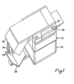
- Figure 1 is a perspective view of a document copier fitted with a document carrier incorporating the invention, and
- Figure 2 is a side view of the apparatus shown in Figure 1.
- Referring to Figure 1, a conventional moving platen photocopier apparatus generally designated 10 is mounted on a
stand 12 and in place of the moving platen there is secured thereto ahousing 14 which overhangs the lefthand end of theunit 10 and includes as an integral unit depending therefrom a wedge-shaped housing 16 having a window therein on the face 18 (shown in Figure 2) for viewing the page of a book or other bound volume located on atrough 20 situated under the wedge-shaped housing 16. - The
trough 20 is supported by aslidable mounting 22 which is acted on by a double-acting pneumatic cylinder located within a leg 24 (the cylinder itself not being shown) and thetrough 20 can be raised or lowered relative to the wedge-shaped housing 16 so as to allow a book located thereon to be offered up to thehousing 16 for scanning or copying. - The wedge-shaped trough is such that the two
side cheeks shaped housing 16 as the book is offered up to the wedge shape. This is best seen in Figure 2 where in dotted outline theplatform 30 on which the twoinclined plates bracket 32 so that a book which has been opened at basically the first page can still be accommodated and centred relative to thewedge 16 so that the open face of the book can be seen through thewindow 18 and will be centred relative thereto. - Although the
leg assembly 24 is shown being supported by two transversely extendingstruts housing 14 and if necessary the upper end of the leg assembly where it is secured to thehousing 14 may be re-inforced to improve rigidity. - Below the
unit 10 and within the space defined by theframework 12 is located a compressor generally designated 38 and other control apparatus. The compressor generates air at sufficient pressure to operate the air cylinder (not shown) for raising and lowering theplatform 30 andtrough 20. - Preferably a relief valve is provided so that as soon as the pressure in the system exceeds a given level the pressure is relieved. By careful selection of this pressure threshold, so the maximum pressure between the book and the surfaces of the wedge-
shaped housing 16 can be controlled so as to reduce the risk of any damage to a book occurring by excess pressure being applied. - The
platform 30 may to advantage be rotatable relative to thestrut 32 so that abook located on the trough can be rotated to present a different page to the viewing window with out the need to touch the book. - Although the
platform 30 is described as being movable relative to thestrut 32 theplates arms platform 30. The arms are in turn attached to the platform throughsprings - If desired, a window or viewing aperture may be provided in the
housing 16 to allow a user to see the face of the document through the window 50 before it is copied. This will allow for accurate positioning of the document relative to the window 50 so that exactly the desired area of the document is either centred or actually in the field of view.
Claims (9)
Applications Claiming Priority (2)
| Application Number | Priority Date | Filing Date | Title |
|---|---|---|---|
| GB08334479A GB2151469B (en) | 1983-12-24 | 1983-12-24 | Improvements in and relating to copiers |
| GB8334479 | 1983-12-24 |
Publications (2)
| Publication Number | Publication Date |
|---|---|
| EP0149897A2 true EP0149897A2 (en) | 1985-07-31 |
| EP0149897A3 EP0149897A3 (en) | 1986-02-19 |
Family
ID=10553851
Family Applications (1)
| Application Number | Title | Priority Date | Filing Date |
|---|---|---|---|
| EP84308440A Ceased EP0149897A3 (en) | 1983-12-24 | 1984-12-05 | Document copier for books |
Country Status (6)
| Country | Link |
|---|---|
| US (1) | US4636868A (en) |
| EP (1) | EP0149897A3 (en) |
| JP (1) | JPS60158766A (en) |
| AU (1) | AU562647B2 (en) |
| DE (1) | DE149897T1 (en) |
| GB (1) | GB2151469B (en) |
Cited By (3)
| Publication number | Priority date | Publication date | Assignee | Title |
|---|---|---|---|---|
| DE3546404A1 (en) * | 1985-12-31 | 1987-07-02 | Pfreimter Hubert | Device for producing double sided reproductions from books |
| DE3819576C1 (en) * | 1988-06-09 | 1989-09-21 | Herrmann & Kraemer Gmbh & Co Kg, 8100 Garmisch-Partenkirchen, De | |
| WO1989009434A1 (en) * | 1988-03-26 | 1989-10-05 | Select Information Systems Limited | Copier with improved platen for books to be copied |
Families Citing this family (5)
| Publication number | Priority date | Publication date | Assignee | Title |
|---|---|---|---|---|
| GB2292281A (en) * | 1994-08-09 | 1996-02-14 | Christie Miller Ian Russell | Wedge shaped scanner for copying partially opened books |
| US5640252A (en) * | 1995-12-12 | 1997-06-17 | Xerox Corporation | Bound document imager with page turner |
| US6233064B1 (en) | 1998-06-27 | 2001-05-15 | Brian David Griffin | Vertically oriented window document scanner |
| US6056258A (en) * | 1998-12-08 | 2000-05-02 | Xerox Corporation | Bound document imager |
| US6459505B1 (en) | 1998-12-08 | 2002-10-01 | Xerox Corporation | Bound document imager |
Citations (5)
| Publication number | Priority date | Publication date | Assignee | Title |
|---|---|---|---|---|
| FR52824E (en) * | 1943-04-08 | 1945-08-10 | Fotokopist G M B H | Continuous photocopying device |
| DE2645595A1 (en) * | 1975-10-10 | 1977-04-21 | Spence Bate | RECORDING TABLE OF A COPY MACHINE |
| FR2498777A1 (en) * | 1981-01-24 | 1982-07-30 | Agfa Gevaert Ag | OPTICAL REPROGRAPHIC APPARATUS |
| DE8207305U1 (en) * | 1982-03-16 | 1983-01-05 | Zeutschel GmbH & Co, 7400 Tübingen | BOOK PRESSURE DEVICE FOR REPRODUCTION EQUIPMENT |
| EP0108625A2 (en) * | 1982-11-05 | 1984-05-16 | The British Library Board | Improvements in and relating to document scanners |
Family Cites Families (7)
| Publication number | Priority date | Publication date | Assignee | Title |
|---|---|---|---|---|
| US2095815A (en) * | 1937-01-15 | 1937-10-12 | Eastman Kodak Co | Masking arrangement for photographic apparatus |
| US3195430A (en) * | 1960-12-28 | 1965-07-20 | Radio Corp Of American | Electrostatic printing apparatus |
| US3712729A (en) * | 1971-08-06 | 1973-01-23 | Itek Corp | Document reproduction apparatus |
| US3726589A (en) * | 1971-11-05 | 1973-04-10 | Eastman Kodak Co | Convertible document feeder and flexible light shield |
| GB2129642B (en) * | 1982-11-05 | 1986-09-10 | British Library Board | Focus detection |
| GB2129646B (en) * | 1982-11-05 | 1986-04-09 | British Library Board | Facsimile scanner for book-copying |
| GB2130044B (en) * | 1982-11-05 | 1986-06-11 | British Library Board | Facsimile pick-up arrangement |
-
1983
- 1983-12-24 GB GB08334479A patent/GB2151469B/en not_active Expired
-
1984
- 1984-12-05 EP EP84308440A patent/EP0149897A3/en not_active Ceased
- 1984-12-05 DE DE198484308440T patent/DE149897T1/en active Pending
- 1984-12-17 US US06/682,158 patent/US4636868A/en not_active Expired - Fee Related
- 1984-12-21 JP JP59271678A patent/JPS60158766A/en active Pending
- 1984-12-21 AU AU37034/84A patent/AU562647B2/en not_active Expired - Fee Related
Patent Citations (5)
| Publication number | Priority date | Publication date | Assignee | Title |
|---|---|---|---|---|
| FR52824E (en) * | 1943-04-08 | 1945-08-10 | Fotokopist G M B H | Continuous photocopying device |
| DE2645595A1 (en) * | 1975-10-10 | 1977-04-21 | Spence Bate | RECORDING TABLE OF A COPY MACHINE |
| FR2498777A1 (en) * | 1981-01-24 | 1982-07-30 | Agfa Gevaert Ag | OPTICAL REPROGRAPHIC APPARATUS |
| DE8207305U1 (en) * | 1982-03-16 | 1983-01-05 | Zeutschel GmbH & Co, 7400 Tübingen | BOOK PRESSURE DEVICE FOR REPRODUCTION EQUIPMENT |
| EP0108625A2 (en) * | 1982-11-05 | 1984-05-16 | The British Library Board | Improvements in and relating to document scanners |
Cited By (4)
| Publication number | Priority date | Publication date | Assignee | Title |
|---|---|---|---|---|
| DE3546404A1 (en) * | 1985-12-31 | 1987-07-02 | Pfreimter Hubert | Device for producing double sided reproductions from books |
| WO1989009434A1 (en) * | 1988-03-26 | 1989-10-05 | Select Information Systems Limited | Copier with improved platen for books to be copied |
| DE3819576C1 (en) * | 1988-06-09 | 1989-09-21 | Herrmann & Kraemer Gmbh & Co Kg, 8100 Garmisch-Partenkirchen, De | |
| US4976408A (en) * | 1988-06-09 | 1990-12-11 | Hermann & Kraemer Gmbh & Co. K.G. | Device for microfilming bound volumes using a tiltable book cradle |
Also Published As
| Publication number | Publication date |
|---|---|
| DE149897T1 (en) | 1986-01-30 |
| GB8334479D0 (en) | 1984-02-01 |
| EP0149897A3 (en) | 1986-02-19 |
| AU562647B2 (en) | 1987-06-18 |
| US4636868A (en) | 1987-01-13 |
| GB2151469B (en) | 1987-08-19 |
| JPS60158766A (en) | 1985-08-20 |
| AU3703484A (en) | 1985-07-04 |
| GB2151469A (en) | 1985-07-24 |
Similar Documents
| Publication | Publication Date | Title |
|---|---|---|
| US4585334A (en) | Document copiers | |
| US4636868A (en) | Copiers | |
| CN100468229C (en) | Image forming device and its assemlbing method | |
| US20030063334A1 (en) | Automatic book page turner for imaging | |
| JP2001024863A (en) | Digital input scanner and digital scanning system | |
| US6056258A (en) | Bound document imager | |
| US6762356B2 (en) | System for turning pages of a material | |
| EP0174731B1 (en) | A book support | |
| US5847884A (en) | Image reading apparatus | |
| US5614991A (en) | Document placement mechanism and image reading device for books | |
| US7440148B2 (en) | System for manipulating pages of a material | |
| US6459505B1 (en) | Bound document imager | |
| US4645332A (en) | Photocopying device | |
| US4976408A (en) | Device for microfilming bound volumes using a tiltable book cradle | |
| US3053007A (en) | Work table for copying machine | |
| CN218337936U (en) | Foldable book support | |
| JPH11298688A (en) | Image reader | |
| CN1621953A (en) | Document handler with improved optics | |
| JPH06250296A (en) | Book original platen | |
| US4459912A (en) | Printing pressure compensating means in pump handle imprinters | |
| JPH0135756B2 (en) | ||
| EP0435972A1 (en) | Multidocument holder with articulating line guide | |
| JPH10279159A (en) | Document discharge mechanism, and image reading device | |
| JPH05262073A (en) | Apparatus for turning page for book type manuscript | |
| JPH0754956B2 (en) | Document reader |
Legal Events
| Date | Code | Title | Description |
|---|---|---|---|
| PUAI | Public reference made under article 153(3) epc to a published international application that has entered the european phase |
Free format text: ORIGINAL CODE: 0009012 |
|
| AK | Designated contracting states |
Designated state(s): AT BE CH DE FR IT LI LU NL SE |
|
| ITCL | It: translation for ep claims filed |
Representative=s name: ING. FISCHETTI WEBER |
|
| TCNL | Nl: translation of patent claims filed | ||
| TCAT | At: translation of patent claims filed | ||
| PUAL | Search report despatched |
Free format text: ORIGINAL CODE: 0009013 |
|
| EL | Fr: translation of claims filed | ||
| DET | De: translation of patent claims | ||
| AK | Designated contracting states |
Designated state(s): AT BE CH DE FR IT LI LU NL SE |
|
| 17P | Request for examination filed |
Effective date: 19860512 |
|
| 17Q | First examination report despatched |
Effective date: 19871207 |
|
| STAA | Information on the status of an ep patent application or granted ep patent |
Free format text: STATUS: THE APPLICATION HAS BEEN REFUSED |
|
| 18R | Application refused |
Effective date: 19880530 |
|
| RIN1 | Information on inventor provided before grant (corrected) |
Inventor name: MALYON, BRIAN RODNEY |