EP0149747A1 - Writing instrument - Google Patents
Writing instrument Download PDFInfo
- Publication number
- EP0149747A1 EP0149747A1 EP19840113786 EP84113786A EP0149747A1 EP 0149747 A1 EP0149747 A1 EP 0149747A1 EP 19840113786 EP19840113786 EP 19840113786 EP 84113786 A EP84113786 A EP 84113786A EP 0149747 A1 EP0149747 A1 EP 0149747A1
- Authority
- EP
- European Patent Office
- Prior art keywords
- writing
- sleeve
- segments
- implement according
- tip
- Prior art date
- Legal status (The legal status is an assumption and is not a legal conclusion. Google has not performed a legal analysis and makes no representation as to the accuracy of the status listed.)
- Granted
Links
Images


Classifications
-
- B—PERFORMING OPERATIONS; TRANSPORTING
- B43—WRITING OR DRAWING IMPLEMENTS; BUREAU ACCESSORIES
- B43K—IMPLEMENTS FOR WRITING OR DRAWING
- B43K5/00—Pens with ink reservoirs in holders, e.g. fountain-pens
- B43K5/16—Pens with ink reservoirs in holders, e.g. fountain-pens with retractable nibs
- B43K5/17—Pens with ink reservoirs in holders, e.g. fountain-pens with retractable nibs with closing means
-
- B—PERFORMING OPERATIONS; TRANSPORTING
- B43—WRITING OR DRAWING IMPLEMENTS; BUREAU ACCESSORIES
- B43K—IMPLEMENTS FOR WRITING OR DRAWING
- B43K24/00—Mechanisms for selecting, projecting, retracting or locking writing units
- B43K24/02—Mechanisms for selecting, projecting, retracting or locking writing units for locking a single writing unit in only fully projected or retracted positions
- B43K24/08—Mechanisms for selecting, projecting, retracting or locking writing units for locking a single writing unit in only fully projected or retracted positions operated by push-buttons
-
- B—PERFORMING OPERATIONS; TRANSPORTING
- B43—WRITING OR DRAWING IMPLEMENTS; BUREAU ACCESSORIES
- B43K—IMPLEMENTS FOR WRITING OR DRAWING
- B43K7/00—Ball-point pens
- B43K7/12—Ball-point pens with retractable ball points
-
- B—PERFORMING OPERATIONS; TRANSPORTING
- B43—WRITING OR DRAWING IMPLEMENTS; BUREAU ACCESSORIES
- B43K—IMPLEMENTS FOR WRITING OR DRAWING
- B43K8/00—Pens with writing-points other than nibs or balls
- B43K8/02—Pens with writing-points other than nibs or balls with writing-points comprising fibres, felt, or similar porous or capillary material
- B43K8/028—Movable closure or gate
-
- B—PERFORMING OPERATIONS; TRANSPORTING
- B43—WRITING OR DRAWING IMPLEMENTS; BUREAU ACCESSORIES
- B43K—IMPLEMENTS FOR WRITING OR DRAWING
- B43K8/00—Pens with writing-points other than nibs or balls
- B43K8/24—Pens with writing-points other than nibs or balls characterised by the means for retracting writing-points
Abstract
Description
Die Erfindung betrifft ein Schreibgerät mit einem hülsenförmigen Gehäuse und einem in diesem Gehäuse angeordneten Schreibelement, welches zwischen einer, den zum Schreiben dienenden Spitzenabschnitt des Schreibelements freigebenden Schreibbereitschaftsstellung und einer in das Gehäuse zurückgezogenen Aufbewahrungsstellung verlagerbar ist, wobei der dem Spitzenabschnitt des Schreibelements benachbarte Gehäuseabschnitt aus Segmenten besteht, die in der Schreibbereitschaftsstellung radial auseinandergespreizt sind und in der Aufbewahrungsstellung aneinander anliegen und das Gehäuse spitzenseitig verschließen.The invention relates to a writing instrument with a sleeve-shaped housing and a writing element arranged in this housing, which writing element can be displaced between a ready-to-write position releasing the tip section of the writing element used for writing and a storage position retracted into the housing, the housing section consisting of segments adjacent to the tip section of the writing element there are, which are radially spread apart in the readiness for writing position and lie against each other in the storage position and close the tip side of the housing.
Ein derartiges Schreibgerät ist z.B. bekannt aus der DE-05 27 52 304. Bei diesem bekannten Schreibgerät sind die Segmente, die in der Aufbewahrungsstellung des Schreibelements das Schreibgerätgehäuse spitzenseitig verschließen sollen, einstükkig mit dem Gehäuse des Schreibgeräts ausgebildet. Der Schließdruck der Segmente wird durch die Elastizität des Materials des Gehäuses hervorgerufen, wenn diese Segmente beim Übergang von der Aufbewahrungsstellung in die Schreibbereitschaftsstellung durch eine entsprechende Schulter am Schreibelement gegen den elastischen Widerstand des Gehäusematerials aufgespreizt werden. Beim Zurückziehen des Schreibelements aus der Schreibbereitschaftsstellung in die Aufbewahrungsstellung gibt die Schulter am Schreibelement die Segmente wieder frei, so daß diese sich nur aufgrund ihrer Elastizität radial nach innen bewegen. Sinn dieser bekannten Anordnung ist es, die Spitze des Schreibelements bzw. Zeichenelements bei Nichtgebrauch zu schützen.Such a writing instrument is e.g. Known from DE-05 27 52 304. In this known writing instrument, the segments which are intended to close the tip of the writing instrument housing in the storage position of the writing element are formed in one piece with the housing of the writing instrument. The closing pressure of the segments is caused by the elasticity of the material of the housing when these segments are spread out against the elastic resistance of the housing material by a corresponding shoulder on the writing element during the transition from the storage position to the readiness to write. When the writing element is withdrawn from the ready-to-write position to the storage position, the shoulder on the writing element releases the segments again, so that they only move radially inward due to their elasticity. The purpose of this known arrangement is to protect the tip of the writing element or drawing element when not in use.
Dieses bekannte Schreibgerät hat den erheblichen Nachteil, daß zwar die bchrsibspitzd bei Nichtgebrauch gegen mechanische Beschädigung geschützt werden kann, es aber nicht möglich ist, die Segmente in der Aufbewahrungsstellung so dicht aneinander anliegen zu lassen, daß sie das Gehäuse spitzenseitig hermetisch dicht verschließen könnten, um ein Austrocknen der Schreibspitze des Schreibelements wirksam verhindern zu können. Ferner wird bei dem bekannten Schreibgerät aufgrund der Tatsache, daß nur die Katerialelastizität für den Schließdruck sorgen kann, im Laufe der Zeit aufgrund von Materialermüdung die Schließfähigkeit des Spitzenabteils des Gerätes nachlassen.This known writing instrument has the considerable disadvantage that that the bchrsibspitzd can be protected against mechanical damage when not in use, but it is not possible to allow the segments to lie so close together in the storage position that they could hermetically seal the tip side to effectively prevent the writing tip of the writing element from drying out to be able to. Furthermore, in the known writing instrument, due to the fact that only the material elasticity can provide the closing pressure, the closing ability of the tip compartment of the device will deteriorate over time due to material fatigue.
Der Erfindung liegt daher die Aufgabe zugrunde, ein Schreibgerät der Eingangs beschriebenen Art zu schaffen, welches bei relativ einfacher Ausgestaltung und Handhabung wirksam verhindern kann, daß austrocknungsgefährdete Schreibelemente bzw. deren Schreibspitzen, wie z.B. Filzschreiber, Tuschschreiber, Füllfederhalter, Kapillarschreiber, Tusch- oder Zeichenpinsel oder dgl. Gerätschaften, in Aufbewahrungsstellung des Schreibgerätes austrocknen können.The invention is therefore based on the object of providing a writing implement of the type described at the outset which, with a relatively simple design and handling, can effectively prevent writing elements or their writing tips, such as e.g. Felt-tip pens, ink pens, fountain pens, capillary pens, ink or drawing brushes or similar devices can dry out in the storage position of the writing instrument.
Diese Aufgabe wird erfindungsgemäß bei einem Schreibgerät der Eingangs beschriebenen Art dadurch gelöst, daß das Gehäuse aus einer äußeren Hülse und einer im wesentlichen innerhalb der äusseren Hülse angeordneten, relativ zu dieser in Axialrichtung begrenzt verschiebbaren inneren Hülse besteht,
- daß die das Verschlußteil des Gehäuses bildenden Segmente an der inneren Hülse gelagert sind und teilweise außerhalb der äußeren Hülse liegen,
- daß die Segmente radial nach außen unter Vorspannung stehen,
- daß der außerhalb der äußeren Hülse liegende Teil des Verschlußteils einen größeren Außendurchmesser als die lichte Weite des spitzenseitigen Endes der äußeren Hülse hat, welcher sich in Richtung auf das Gehäuseinnere im wesentlichen auf den Durchmesser der inneren Hülse verjüngt,
- daß die innere Hülse über eine sich-an der äußeren Hülse abstützende Feder in Richtung auf die Aufbewahrungsstellung vorbelastet ist, wobei der Federdruck durch die Wechselwirkung zwischen dem sich verjüngenden Teil des Verschlußteils un der spitzenseitigen Öffnung der äußeren Hülse in einen radialen Schließdruck der Segmente umgesetzt wird,
- und daß die innere Hülse mittels eines Betätigungselementes gegen den Druck der Feder axial verschiebbar ist.
- that the segments forming the closure part of the housing are mounted on the inner sleeve and are partially outside the outer sleeve,
- that the segments are preloaded radially outwards,
- that the part of the closure part lying outside the outer sleeve has a larger outer diameter than the inside width of the tip-side end of the outer sleeve, which tapers essentially towards the diameter of the inner sleeve in the direction of the housing interior,
- that the inner sleeve is biased toward the storage position via a spring supported on the outer sleeve, the spring pressure due to the interaction between the tapering part of the closure part and the tip-side opening of the outer sleeve in a radial closing pressure the segments are implemented,
- and that the inner sleeve is axially displaceable against the pressure of the spring by means of an actuating element.
Bei diesem erfindungsgemäßen Schreibgerät wird der Schließdruck des Verschlußteils bzw. der Segmente des Verschlußteils nicht durch die Materialelastizität gewährleistet, sondern durch nach den Erfordernissen wählbaren Federdruck, der durch das Zusammenwirken zwischen Verschlußspitze und Gehäuse des Schreibgerätes in den Schließdruck umgesetzt wird. Dies hat zur Folge, daß ein für ein hermetisches Abdichten ausreichender Schließdruck erzeugt werden kann und dieser auch erhalten -bleibt. Notfalls kann die Spannfeder bei Ermüdung ohne Probleme ersetzt werden. Außerdem wird eine Kollision der Schreibelementspitze mit dem Verschlußteil wirksam vermieden, da erst das Verschlußteil geöffnet wird und erst dann das Schreibelement vorgeschoben wird.In this writing instrument according to the invention, the closing pressure of the closure part or the segments of the closure part is not guaranteed by the material elasticity, but by spring pressure which can be selected according to the requirements and which is converted into the closing pressure by the interaction between the closure tip and the housing of the writing instrument. The result of this is that a closing pressure sufficient for hermetic sealing can be generated and this pressure is maintained. In the event of fatigue, the tension spring can be replaced without any problems. In addition, a collision of the writing element tip with the closure part is effectively avoided, since only the closure part is opened and only then is the writing element advanced.
Vorteilhafterweise können am Schreibgerät, wenn dieses durch sein Eigengewicht in Schreibbereitschaftsstellung bzw. in Aufbewahrungsstellung gebracht wird, Vorsprünge zur Begrenzung der Axialbewegung des Schreibelements vorgesehen sein, die mit Innenwülsten an der Zwischenhülse zusammenwirken, um das Schreibelement in der Schreibbereitschaftsstellung festlegen zu können. Diese Vorsprünge können vorteilhafterweise auf einer separaten, auf den vorderen Teil des Schreibelements aufschiebbaren Funktionshülse angeordnet sein, die ggf. beim Schreibelementwechsel im Gehäuse verbleiben kann.Advantageously, projections for limiting the axial movement of the writing element can be provided on the writing instrument when it is brought into the ready-to-write position or into the storage position by its own weight, said projections cooperating with inner beads on the intermediate sleeve in order to be able to fix the writing element in the ready-to-write position. These projections can advantageously be arranged on a separate functional sleeve which can be pushed onto the front part of the writing element and which may remain in the housing when the writing element is changed.
Außerdem kann es vorteilhaft sein, das Gehäuse mit einer Verlängerung zu versehen, welche das Verschlußteil in Aufbewahrungsstellung übergreift und so gegen mechanische Beschädigung schützt.In addition, it can be advantageous to provide the housing with an extension which engages over the closure part in the storage position and thus protects against mechanical damage.
Bei einem Schreibgerät der bekannten Art, bei welchem das Schreibelement mittels einer sich am Gehäuse abstützenden Feder in Richtung auf die Aufbewahrungsstellung vorbelastet ist und mittels einer durch das Betätigungselement betätigbaren Schaltmechanik gegen den Federdruck in Schreibbereitschaftsstellung relativ zum Gehäuse festlegbar ist, wird die oben beschriebene Aufgabe vorteilhafterweise dadurch gelöst, daß sich die das Schreibelement gegen das Gehäuse vorbelastende Feder an der inneren Hülse abstützt, daß die Schaltmechanik an der äußeren Hülse angreift, daß die Rückstellkraft der das Schreibelement gegen die innere Hülse vorspannenden Feder kleiner ist, als die Feder, die die innere Hülse gegen die äußere Hülse vorspannt, und daß die innere Hülse gegen die äußere Hülse in Schreibbereitschaftsstellung festgelegt wird durch Wechselwirkung zwischen den Segmenten und Schreibelement einerseits und äußeren Hülse andererseits.In a writing instrument of the known type, in which the writing element is preloaded in the direction of the storage position by means of a spring which is supported on the housing and by means of a switching mechanism which can be actuated by the actuating element, against the spring pressure in the readiness to write position can be fixed relative to the housing, the object described above is advantageously achieved in that the spring biasing the writing element against the housing is supported on the inner sleeve, that the switching mechanism acts on the outer sleeve, that the restoring force of the writing element against the inner sleeve biasing spring is smaller than the spring that biases the inner sleeve against the outer sleeve, and that the inner sleeve against the outer sleeve is set in the readiness position by interaction between the segments and writing element on the one hand and the outer sleeve on the other.
Dabei ist im wesentlichen jede der bekannten Schaltmechaniken verwendbar, um die Zwischenhülse und das Schreibelement aus der Aufbewahrungsstellung in die Schreibbereitschaftsstellung zu verschieben und dort festzulegen.Essentially, each of the known switching mechanisms can be used to move the intermediate sleeve and the writing element from the storage position into the ready-to-write position and to fix it there.
In diesem Falle ist das Schreibelement vorteilhafterweise mit mehreren Steuervorsprüngen versehen, die mit der Schaltmechanik zusammenwirken, um das Schreibelement unabhängig von der Zwischenhülse in der Schreibbereitschaftsstellung zu fixieren. Dabei kann die Schaltmechanik vorteilhafterweise bestehen aus einem separaten Schaltring, der längsverschiebbar zwischen der Zwischenhülse und der äußeren Hülse angeordnet ist, und zusammenwirkt mit Führungsnuten, die auf der Innenfläche der äußeren Hülse vorgesehen sind, und mit Schaltzähnen, die am Betätigungselement vorgesehen sind.In this case, the writing element is advantageously provided with a plurality of control projections which interact with the switching mechanism in order to fix the writing element in the readiness to write position independently of the intermediate sleeve. The switching mechanism can advantageously consist of a separate switching ring which is arranged to be longitudinally displaceable between the intermediate sleeve and the outer sleeve, and interacts with guide grooves which are provided on the inner surface of the outer sleeve and with switching teeth which are provided on the actuating element.
Da die Zwischenhülse in diesem Falle für den Durchgriff der Steueruorsprünge geschlitzt sein muß, ist vorteilhafterweise das Betätigungselement mit Ausnehmungen versehen, in welchen die Endkante der Zwischenhülse zur Stabilisierung aufgenommen sein kann.Since in this case the intermediate sleeve must be slotted for the control jumps to pass through, the actuating element is advantageously provided with recesses in which the end edge of the intermediate sleeve can be received for stabilization.
In einer anderen Version kann die Schaltmechanik an der inneren Hülse des Gehäuses angreifen, wobei dann die Rückstellkraft der das Schreibelement gegen die innere Hülse vorspannenden Feder größer ist als die der Feder, die die innere Hülse gegen die äußere Hülse vorspannt.In another version, the switching mechanism can act on the inner sleeve of the housing, in which case the restoring force of the spring that biases the writing element against the inner sleeve is greater than that of the spring that biases the inner sleeve against the outer sleeve.
Die Federn sind dann vorteilhafterweise so bemessen, daß sich bei Betätigung des Betätigungselementes der Druck auf die beiden Federn zuerst nur auf die die Zwischenhülse gegen das Gehäuse abstützende Feder auswirkt, so daß, bis sich das Verschlußteil ausreichend geöffnet hat, das Schreibelement relativ zur Zwischenhülse nicht verschoben werden kann.The springs are then advantageously dimensioned such that when the actuating element is actuated, the pressure on the two springs first affects only the spring that supports the intermediate sleeve against the housing, so that until the closure part has opened sufficiently, the writing element does not relative to the intermediate sleeve can be moved.
Diese Sicherung kann zusätzlich unterstützt werden, durch an der Innenseite der Segmente des Verschlußteils vorgesehene Vorsprünge, die in eine entsprechende Schulter des Schreibelements eingreifen, so daß dieses relativ zur Zwischenhülse axial nicht verschoben werden kann, ehe sich das Verschlußteil ausreichend geöffnet hat. Der Federweg der die Zwischenhülse gegen das Gehäuse abstützenden Feder kann begrenzt werden durch eine entsprechende geometrische Bemessung der Feder oder durch einen Rückhaltevorsprung an der Zwischenhülse, der die Axialverschiebung der Zwischenhülse und damit den Federweg begrenzt.This securing can be additionally supported by projections provided on the inside of the segments of the closure part, which engage in a corresponding shoulder of the writing element, so that the latter cannot be displaced axially relative to the intermediate sleeve until the closure part has opened sufficiently. The spring travel of the spring supporting the intermediate sleeve against the housing can be limited by a corresponding geometric dimensioning of the spring or by a retaining projection on the intermediate sleeve, which limits the axial displacement of the intermediate sleeve and thus the spring travel.
Von besonderem Vorteil kann es sein, wenn ein Teil der Schaltmechanik einstückig mit dem Schreibelement ausgebildet ist. In diesem Fall kann die Zwischenhülse als kurze Halbhülse ausgestaltet sein, die vorteilhafterweise einen Flansch am nach hinten gerichteten Ende aufweist, an dem sich die die Zwischenhülse gegen das Schreibelement vorspannende Feder vorteilhafterweise über gleitfähige Ringe abstützt.It can be particularly advantageous if part of the switching mechanism is formed in one piece with the writing element. In this case, the intermediate sleeve can be designed as a short half-sleeve, which advantageously has a flange at the rearward end, on which the spring biasing the intermediate sleeve against the writing element is advantageously supported via slidable rings.
In der Zwischenhülse kann vorteilhafterweise eine weitere dazu koaxiale Hülse angeordnet sein, die anstelle des Schreibelements gegen die Zwischenhülse vorgespannt ist. Diese Zwischenhülse kann vorteilhafterweise durch geeignete Rückhaltvorsprünge bzw. Wülste in der Zwischenhülse gegen den Federdruck zurückgehalten werden. Außerdem kann vorteilhafterweise in dieser Zwischenhülse ein Füllfedersystem angeordnet sein.A further sleeve which is coaxial to it and which is biased against the intermediate sleeve instead of the writing element can advantageously be arranged in the intermediate sleeve. This intermediate sleeve can advantageously be retained against the spring pressure by suitable retention projections or beads in the intermediate sleeve. In addition, a fountain pen system can advantageously be arranged in this intermediate sleeve.
Um einen besonders einfachen Patronen- oder Schreibelementwechsel zu ermöglichen, kann die Zwischenhülse an ihrem rückwärtigen Ende in diesem Falle offen ausgestaltet sein und die Patrone bzw. das Schreibelement mit einem Greifansatz zum Herausziehen versehen sein.In order to enable a particularly simple change of cartridge or writing element, the intermediate sleeve can in this case be open at its rear end and the cartridge or writing element can be provided with a gripping attachment for pulling out.
Zur Verbesserung der hermetischen Dichtwirkung der Segmente können deren aneinander anliegenden Kanten vorteilhafterweise mit einer uichtung versehen sein und/oder komplementär zueinander profiliert sein.To improve the hermetic sealing effect of the segments, their abutting edges can advantageously be provided with an opening and / or can be profiled to complement each other.
Um die Dichtwirkung bzw. den Schutz vor Austrocknung noch erheblich zu verbessern, können vorteilhafterweise-an den Segmenten auf der dem Schreibelement zugewandten Seite Dichtwulstsegmente angeordnet sein, die in der Aufbewahrungsstellung aneinander und an dem Schreibelement dichtend anliegen und so mit den aneinander anliegenden Segmentkanten eine den Schreibelementspitzenabschnitt umgebende, hermetisch dichte Kammer bilden.In order to significantly improve the sealing effect or the protection against dehydration, sealing bead segments can advantageously be arranged on the segments on the side facing the writing element, which, in the storage position, bear against one another and against the writing element and thus one with the abutting segment edges Form the hermetically sealed chamber surrounding the writing element tip section.
Dabei reicht es aus, und kann sogar von Vorteil sein, wenn die an den Segmentkanten vorgesehenen Dichtungen jeweils nur von der Segmentspitze bis zur Höhe der Dichtwulstsegmente verlaufen. Dadurch kann es einfacher sein, das gesamte-Verschlußteil aus einem Teil herzustellen, da die Dichtung dann nur im weiter aufspreizbaren Teil des Verschlußteils angebracht werden muß.It is sufficient and can even be advantageous if the seals provided on the segment edges only run from the segment tip to the height of the sealing bead segments. This can make it easier to manufacture the entire closure part from one part, since the seal then only has to be attached in the part of the closure part which can be expanded further.
Von besonderem Vorteil kann es sein, wenn die einzelnen Segmente separat hergestellt werden und in einem lösbar an der Zwischenhülse befestigten Zwischenring gelagert und gehalten sind. Dieser Ring kann vorteilhafterweise aus elastischem Material bestehen, in welchem die Segmente schräg nach außen zur Axialrichtung des Zwischenrings gelagert sind, so daß die Elastizität des Zwischenrings die radiale Vorspannung der begmente unterstützt.It can be particularly advantageous if the individual segments are manufactured separately and are stored and held in an intermediate ring which is detachably attached to the intermediate sleeve. This ring can advantageously consist of elastic material, in which the segments are mounted obliquely outwards to the axial direction of the intermediate ring, so that the elasticity of the intermediate ring supports the radial prestressing of the grafts.
Es kann auch an einer Stelle, die in der Aufbewahrungsstellung den Segmenten gegenüberliegt, ein Dichtring (23') oder -überzug (71) angeordnet sein, an dem die Segmentinnenflächen zur Anlage kommen und so mit dem Dichtring eine den Spitzenabschnitt des Schreibelements (2) umgebende, hermetisch dichte Kammer (6) bilden.A sealing ring (23 ') or coating (71) can also be arranged at a point opposite the segments in the storage position, against which the inner surfaces of the segments come to rest and so that the sealing ring adopts the tip section of the writing element (2). Form the surrounding, hermetically sealed chamber (6).
Die Ausgestaltung der Kinenspitze mit einem Dichtring oder einem Dichtüberzug hat den Vorteil, daß die Segmentinnenseiten ohne Dichtwulstelemente ausgestaltet werden können, was deren Herstellung erheblich erleichtert. Außerdem ist durch diese erfindungsgemäße Ausgestaltung sichergestellt, daß bei jedem Minenwechsel gleichzeitig eine frische Dichtung für die den Spitzenabschnitt des Schreibelements umgebende Kammer mitgeliefert wird. Zusätzlich hat der Dichtring den Vorteil, daß er als Vorschubsicherung des Schreibelementes in Aufbewahrungsstellung dienen kann,The design of the kin tip with a sealing ring or a sealing coating has the advantage that the inside of the segment can be designed without sealing bead elements, which makes their manufacture considerably easier. In addition, this configuration according to the invention ensures that a fresh seal for the chamber surrounding the tip section of the writing element is supplied with each refill change. In addition, the sealing ring has the advantage that it can serve to secure the writing element in the storage position,
Eine besonders einfache Ausgestaltungsform des erfindungsgemäßen Schreibgerätes sieht vor, daß die Innenflächenbereiche -der Segmente komplementär zur Form des Spitzenabschnittes des Schreibelementes ausgestaltet sind und in der Aufbewahrungsstellung dichtend an der Minenspitze selbst zur Anlage kommen können. Dadurch ist das Vorsehen von jeglichen Dichtwülsten überflüssig geworden, was die Herstellung des Schreibgerätes weiter vereinfacht. Zur Verbesserung der Dichtwirkung zwischen Segmenten und Minenspitze kann die Innenfläche der Segmente gummielastisch ausgebildet sein, oder mit einem gummielastischen Überzug versehen sein. In gleicher Weise kann auch die Oberfläche der Minenspitze im Anlagebereich gummielastisch ausgebildet sein.A particularly simple embodiment of the writing instrument according to the invention provides that the inner surface areas of the segments are designed to be complementary to the shape of the tip section of the writing element and, in the storage position, can come into sealing contact with the tip of the lead itself. As a result, the provision of any sealing beads has become superfluous, which further simplifies the manufacture of the writing instrument. To improve the sealing effect between the segments and the tip of the lead, the inner surface of the segments can be made rubber-elastic, or can be provided with a rubber-elastic coating. In the same way, the surface of the lead tip in the contact area can also be made rubber-elastic.
Eine besonders für Füllfederhalter günstige Ausgestaltungsform des erfindungsgemäßen Schreibelementes zeichnet sich dadurch aus, daß die innere Hülse (74) teilschalig augebildet ist und daß die Segmentspitze (8') einstückig als teilschaliges Verschlußteil ausgebildet ist, das über ein elastisch nach außen vorgespanntes Übergangsteil mit der inneren Hülse verbunden ist.An embodiment of the writing element according to the invention which is particularly advantageous for fountain pens is characterized in that the inner sleeve (74) is formed in part-shell and in that the segment tip (8 ') is formed in one piece as a part-shell closure part which is connected to the inner part via an elastically biased transition part Sleeve is connected.
Die teilschalige Ausgestaltungsform des Verschlußteiles hat den Vorteil, daß sie bestmöglich an die Konturen einer Füllfederhalterspitze angepaßt werden kann. Außerdem ist die einstükkige Ausgestaltung des Verschlußteiles erheblich einfacher in der Herstellung.The partial-shell design of the closure part has the advantage that it can be adapted as best as possible to the contours of a fountain pen tip. In addition, the one-piece design of the closure part is considerably easier to manufacture.
Vorteilhafterweise kann die innere Hülse mit der Segmentspitze einstückig ausgebildet sein, wodurch nur ein Herstellungsschritt notwendig wird.The inner sleeve can advantageously be formed in one piece with the segment tip, as a result of which only one manufacturing step is necessary.
Zur Gewährleistung einer guten Abdichtung der spitzenseitigen Kammer kann im Verschlußteil ein Dichtwulstelement angeordnet sein, das in der Aufbewahrungsstellung dichtend am Spitzenabschnitt des Schreibelementes zur Anlage kommt. Auch dieses Dichtwulstsegment kann wiederum einstückig mit dem Verschlußteil ausgebildet sein.To ensure a good seal of the tip-side chamber, a sealing bead element can be arranged in the closure part, which comes to bear sealingly against the tip section of the writing element in the storage position. This sealing bead segment can also be formed in one piece with the closure part.
Bei einem aus mehreren Segmenten bestehenden Verschlußteil bei einem Schreibgerät der oben genannten Art können vorteilhafterweise die Kanten der einzelnen Segmente miteinander durch dünnwandige, elastische Segmentverbindungen verbunden sein, die in Aufbewahrungsstellung nach innen eingefaltet sind. Dies hat'den Vorteil, daß erstens keine Dichtungen mehr auf den Segmentkanten aufgebracht werden müssen und daß zweitens eine absolute Dichtigkeit zur Seite gewährleistet ist.In the case of a closure part consisting of several segments in a writing instrument of the type mentioned above, the edges of the individual segments can advantageously be connected to one another by thin-walled, elastic segment connections which are folded inwards in the storage position. This has the advantage that, firstly, seals no longer have to be applied to the segment edges and, secondly, that absolute tightness to the side is guaranteed.
Ein Schreibgerät der eingangs genannten Art kann weiterhin dadurch verbessert werden, daß die innere Hülse aus zwei miteinander verbundenen Zylindern unterschiedlichen Durchmessers besteht, wobei die eine Feder außerhalb des dünneren und die andere Feder innerhalb des dickeren Zylinders angeordnet ist. Diese Ausgestaltungsform hat den erheblichen Vorteil, daß die radialen Abmessungen des Schreibgerätes, speziell des Außengehäuses des Schreibgerätes, kleiner gewählt werden können, wodurch das gesamte Schreibgerät schlanker und somit optisch ansprechender wird.A writing instrument of the type mentioned can be further improved in that the inner sleeve consists of two interconnected cylinders of different diameters, one spring being arranged outside the thinner cylinder and the other spring being arranged inside the thicker cylinder. This embodiment has the considerable advantage that the radial dimensions of the writing instrument, especially the outer casing of the writing instrument, can be chosen to be smaller, as a result of which the entire writing instrument becomes slimmer and thus more visually appealing.
Zur Vereinfachung des Minenwechsels bei einem Schreibgerät der eingangs genannten Art ist es von Vorteil, wenn die äußere Hülse (1) nach hinten offen ist und die innere Hülse (7.) in Aufbewahrungsstellung nach hinten aus der äußeren Hülse (1) herausragt. Dadurch, daß die innere Hülse nach hinten aus der äußeren Hülse herausragt, kann der hintere Teil der inneren Hülse, der über ein Schraubgewinde mit dem vorderen Teil verbunden ist für einen Minenwechsel abgeschraubt werden, ohne daß die äußere Hülse vorher aufgeschraubt werden müßte. Dadurch ist der Minenwechsel erheblich vereinfacht..To simplify the change of refills in a writing instrument of the type mentioned at the outset, it is advantageous if the outer sleeve (1) is open to the rear and the inner sleeve (7.) Protrudes rearward from the outer sleeve (1) in the storage position. Characterized in that the inner sleeve protrudes rearwards from the outer sleeve, the rear part of the inner sleeve, which is connected to the front part via a screw thread, can be unscrewed for a mine change without the outer sleeve having to be screwed on beforehand. This significantly simplifies mine replacement.
Die Verschlußwirkung der Segmente des erfindungsgemäßen Schreibgerätes kann dadurch verbessert werden, daß die Außenfläche des Verschlußteils sich in zwei Stufen unterschiedlicher Neigung zur Längsachse nach hinten verjüngt, wobei der Teil schwächerer Neigung dem Spitzenteil zugewandt liegt. Durch die erfindungsgemäße zweistufige Neigungsgestaltung ist ein zweistufiger Schließvorgang gewährleistet. Beim Verschließen des Schreibgerätes kommt der freie Rand des spitzenseitigen Endes der äußeren Eülle zuerst in Berührung mit dem stark geneigten Außenflächenbereich des Uerschlußteiles. Dadurch ist gewährleistet, daß das Schreibelement zuerst vollständig in die Innenhülse hineinbewegt wird, bevor die radiale Verschlußbewegung dann bei Erreichen der starken Neigung sehr schnell einsetzt. Andererseits wird durch die schwächere keigung der Außenfläche des Verschlußteiles in der zweiten Verschlußstufe ein größerer Schließdruck der Segmente gegeneinander erreicht. Dadurch wird die Dichtwirkung der erfindungsgemäßen Segmentelemente noch weiter verbessert.The locking effect of the segments of the writing instrument according to the invention can be improved in that the outer surface che of the closure part tapers in two stages of different inclination to the longitudinal axis to the rear, the part with a weaker inclination facing the tip part. The two-stage incline design according to the invention ensures a two-stage closing process. When the writing instrument is closed, the free edge of the tip-side end of the outer spout first comes into contact with the strongly inclined outer surface area of the closing part. This ensures that the writing element is first completely moved into the inner sleeve before the radial locking movement then begins very quickly when the strong inclination is reached. On the other hand, the weaker inclination of the outer surface of the closure part in the second closure stage achieves a greater closing pressure of the segments against one another. This further improves the sealing effect of the segment elements according to the invention.
Wenn das erfindungsgemäße Schreibgerät, speziell die erfindungsgemäße Verschlußmechanik für Kapillarschreiber verwendet werden soll, so ist es vorteilhafterweise so ausgestaltet, daß auf der Innenseite der Segmentspitze eine Dichtfläche für die Spitze und den zendelausgang angeordnet ist, und daß das Betätigungselement auf die innere Hülse einwirkt und nach einer begrezten Axialverschiebung der inneren Hülse in Kontakt mit dem Schreibelement kommt und auf dieses einwirkt und es axial verschiebt. Einerseits wird durch das Vorsehen der Dichtfläche für die Spitze und den Wendelausgang gewährleistet, daß in der Aufbewahrungsstellung des Schreibgerätes keine Tusche oder dgl. aus der Kapillare und dem Wendelausgang austreten kann. Andererseits ist durch die erfindungsgemäße Ausgestaltung des Betätigungselementes gewährleistet, daß auch bei einem beispielsweise Tuscheschreiber eine einfache Bedienung durch eine Druckmechanik erreicht ist. Dadurch daß das Betätigungselement, bevor es mit dem Schreibelement in Kontakt kommt, auf die innere Hülse einwirkt, ist sichergestellt, daß die Kapillarspitze und der Uendelausgang von der Dichtfläche freikommt, ehe die radiale Öffnungsbewegung der Segmentspitze, an der die Dichtfläche befestigt ist, einsetzt. Dadurch ist eine Versetzung der Kapillarspitze wirksam vermieden. Durch diese erfindungsgemäße Ausgestaltung des Schreibgerätes ist erstmals ein Tusche- oder Kapillarschreiber geschaffen, bei welchem ohne jede Kappe, die verloren werden könnte, eine absolute Dichtigkeit des Schreibers gewährleistet ist.If the writing instrument according to the invention, especially the closure mechanism according to the invention for capillary recorders is to be used, it is advantageously designed such that a sealing surface for the tip and the zendel output is arranged on the inside of the segment tip, and that the actuating element acts on the inner sleeve and after a pronounced axial displacement of the inner sleeve comes into contact with and acts on the writing element and moves it axially. On the one hand, the provision of the sealing surface for the tip and the spiral outlet ensures that no ink or the like can escape from the capillary and the spiral outlet in the storage position of the writing instrument. On the other hand, the design of the actuating element according to the invention ensures that simple operation by means of a printing mechanism is achieved even in a pen, for example. The fact that the actuating element acts on the inner sleeve before it comes into contact with the writing element ensures that the capillary tip and the exit end of the seal are released from the sealing surface before the radial opening movement of the segment tip to which the sealing surface is attached begins. This effectively prevents displacement of the capillary tip. With this configuration of the writing instrument according to the invention, an ink or capillary pen is created for the first time, at wel chem without any cap that could be lost, an absolute tightness of the pen is guaranteed.
Im folgenden werden anhand der beiliegenden Zeichnungen sieben Ausführungsbeispiele des Schreibgerätes näher beschrieben.Seven exemplary embodiments of the writing instrument are described in more detail below with reference to the accompanying drawings.
Es zeigen:
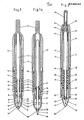
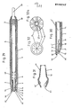
- Fig. 1 einen Längsschnitt durch eine Ausführungsform des Schreibgerätes in der Verschluß-, bzw. Ruhestellung,
- Fig. 1a einen Längsschnitt durch das Schreibgerät von Fig. 1 in der Schreibstellung,
- Fig. 2 einen Längsschnitt durch eine weitere Ausführungsform des Schreibgerätes in der Verschlußstellung,
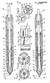
- Fig. 3 einen Längsschnitt durch eine weitere Ausführungsform des Schreibgerätes in der Verschlußstellung,
- Fig. 3a einen Längsschnitt durch das Schreibgerät von Fig. 3 in der Schreibstellung,
- Fig. 4 einen Querschnitt durch das Schreibgerät nach Fig. 3a,
- Fig. 5 einen Längsschnitt durch den hinteren Teil der Zwischenhülse (7) nach Fig. 3,
- Fig. 6 einen teilweise weggebrochenen Längsschnitt durch den vorderen Teil des Betätigungselements (sowie Spann- und Schaltelement) (11) nach Fig. 3,
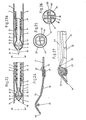
- Fig. 7-7c Längsschnitte durch eine weitere Ausführungsform des Schreibgerätes in verschiedenen Ruhe-, Schalt- usw. Phasen,
- Fig. 8 einen Längsschnitt durch eine weitere Ausführungsform des Schreibgerätes in Ruhestellung,
- Fig. 8a einen Längsschnitt durch das Schreibgerät von Fig. B in Schreibstellung,
- Fig. 9 einen Querschnitt durch den Spitzenabschnitt des Schreibgerätes nach Fig. 8,
- Fig. 10 einen Querschnitt durch den Spitzenabschnitt des Schreibgerätes nach Fig. 8a,
- Fig. 11 eine abgerollte Innenansicht der Führungsnuten (51) der Schaltmechanik von Fig. 8,
- Fig. 12 eine Vorderansicht des Spitzenteils des Schreibgerätes von Fig. 8,
- Fig. 13 eine Vorderansicht des Spitzenteils des Schreibgerätes von Fig. 8a,
- Fig. 14 einen Längsschnitt durch eine weitere Ausführungsform des Schreibgerätes in Ruhestellung,
- Fig. 14a einen Längsschnitt durch das Schreibgerät von Fig. 14 in Schreibstellung,
- Fig. 15a-h Details (bzw. Teilquerschnitte) verschiedener Ausführungsformen des Spitzenteils des Schreibgerätes,
- Fig. 16 eine Vorderansicht nach Fig. 15d,f,g,
- Fig. 17 eine Vorderansicht nach Fig. 1Se,h,
- Fig. 18 eine Vorderansicht nach Fig. 1Sa,b,c,
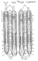
- Fig. 19 einen Teilquerschnitt durch eine Ausführungsform zur Erläuterung der hermetischen Kammer (Segmentkammer) in der Spitze des Gerätes,
- Fig. 20 eine schematische Ansicht der Dichtlinien der hermetischen Segmentkammer entsprechend Fig. 19,
- Fig. 21 eine teilweise weggebrochene (sowie geschnittene) perspektivische Vorderansicht der Spitze des Schreibgerätes (mit geschnittener, hermetischer Segmentkammer), nach Fig. 19
und 20, - Fig. 22a-l ein Modell der Funktionsebläufe und Schubbewegungen der Ausführungsbeispiele nach den Figuren: 2, 7-7c, 8 und 8a, 14 und 14a, 23 und 23a,
- Fig. 23 einen Teillängsschnitt durch eine weitere Ausführungsform des Schreibgerätes in Ruhestellung,
- Fig. 23a einen Teillängsschnitt durch das Schreibgerät nach Fig. 23 in Schreibstellung,
- Fig. 24 einen Querschnitt durch Teile der Verschlußanordnung einer weiteren Ausführungsform des Schreibgerätes,
- Fig. 25 eine Vorderansicht des Spitzenteils des Schreibgerätes von Fig. 23,
- Fig. 26 eine Vorderansicht des Spitzenteils des Schreibgerätes von Fig. 23a,
- Fig. 27 ein teilweise weggebrochenes einzelnes Aufbiegesegment (34) aus dem Verschlußteil (8) des Schreibgerätes von Fig. 23,
- Fig. 28-28c Längsschnitte durch eine Ausführungsform des Schreibgerätes in verschiedenen Ruhe-, schalt- usw. Phasen,
- Fig. 29 einen Längsschnitt durch eine weitere Ausführungsform des Schreibgerätes,
- Fig. 30 einen Teillängsschnitt durch eine weitere Ausführungsform des Schreibgerätes,
- Fig. 31 einen Längsschnitt durch das Verschlußteil einer weiteren Ausführungsform des Schreibgerätes,
- Fig. 32 eine Vorderansicht des geschlossenen Spitzenteils einer weiteren Ausführungsform des Schreibgerätes,
- Fig. 32a eine Vorderansicht des Spitzenteils aus Fig. 5 in geöffnetem Zustand,
- Fig. 33 einen Längsschnitt durch eine weitere Ausführungsform des Schreibgerätes.
- 1 shows a longitudinal section through an embodiment of the writing instrument in the closed or rest position,
- 1a shows a longitudinal section through the writing instrument of FIG. 1 in the writing position,
- 2 shows a longitudinal section through a further embodiment of the writing instrument in the closed position,
- 3 shows a longitudinal section through a further embodiment of the writing instrument in the closed position,
- 3a shows a longitudinal section through the writing instrument of FIG. 3 in the writing position,
- 4 shows a cross section through the writing instrument according to FIG. 3a,
- 5 shows a longitudinal section through the rear part of the intermediate sleeve (7) according to FIG. 3,
- 6 is a partially broken longitudinal section through the front part of the actuating element (and tensioning and switching element) (11) according to FIG. 3,
- 7-7c longitudinal sections through a further embodiment of the writing instrument in various rest, switching, etc. phases,
- 8 shows a longitudinal section through a further embodiment of the writing instrument in the rest position,
- 8a shows a longitudinal section through the writing instrument of FIG. B in the writing position,
- 9 shows a cross section through the tip section of the writing instrument according to FIG. 8,
- 10 shows a cross section through the tip section of the writing instrument according to FIG. 8a,
- Fig. 11 is a rolled-up inside view of the guide grooves (51) of the Switching mechanism of Fig. 8,
- 12 is a front view of the tip part of the writing instrument of FIG. 8,
- 13 is a front view of the tip part of the writing instrument of FIG. 8a,
- 14 shows a longitudinal section through a further embodiment of the writing instrument in the rest position,
- 14a shows a longitudinal section through the writing instrument of FIG. 14 in the writing position,
- 15a-h details (or partial cross-sections) of different embodiments of the tip part of the writing instrument,
- 16 is a front view of FIG. 15d, f, g,
- 17 is a front view of FIG. 1Se, h,
- 18 is a front view of FIG. 1Sa, b, c,
- 19 shows a partial cross section through an embodiment to explain the hermetic chamber (segment chamber) in the tip of the device,
- Fi g . 20 shows a schematic view of the sealing lines of the hermetic segment chamber corresponding to FIG. 19,
- 21 is a partially broken (as well as cut) perspective front view of the tip of the writing instrument (with a cut, hermetic segment chamber), according to FIGS. 19 and 20,
- 22a-l a model of the functional sequences and thrust movements of the exemplary embodiments according to the figures: 2, 7-7c, 8 and 8a, 14 and 14a, 23 and 23a,
- 23 shows a partial longitudinal section through a further embodiment of the writing instrument in the rest position,
- 23a shows a partial longitudinal section through the writing instrument according to FIG. 23 in the writing position,
- 24 shows a cross section through parts of the closure arrangement of a further embodiment of the writing instrument,
- 25 is a front view of the tip portion of the writing instrument of FIG. 23;
- 26 is a front view of the tip portion of the writing instrument of FIG. 23a.
- 27 is a partially broken open segment (34) from the closure part (8) of the writing instrument of FIG. 23,
- 28-28c longitudinal sections through an embodiment of the writing instrument in various rest, switching, etc. phases,
- 29 shows a longitudinal section through a further embodiment of the writing instrument,
- 30 shows a partial longitudinal section through a further embodiment of the writing instrument,
- 31 shows a longitudinal section through the closure part of a further embodiment of the writing instrument,
- 32 is a front view of the closed tip part of a further embodiment of the writing instrument,
- 32a is a front view of the tip part of FIG. 5 in the open state,
- 33 shows a longitudinal section through a further embodiment of the writing instrument.
Das in Fig. 1 (bzw. 1a) dargestellte Ausführungsbeispiel des Schreibgerätes besitzt ein hülsenförmiges, bevorzugt zweiteiliges Gehäuse 1 und 31, sowie eine darin angeordnete Zwischenhülse 7, welche an ihrem, der Schreibspitze zugewandten Ende, mit einem hermetisch abdichtbaren Verschlußteil 8 und an ihrem hinteren Ende mit einem Betätigungselement 15 versehen ist, sowie schließlich einem in dem Schreibgerät befindlichen Schreibelement 2 mit einem flüssigen und in der Regel verdunstungsgefährdeten Schreibmittel.The embodiment of the writing instrument shown in Fig. 1 (or 1a) has a sleeve-shaped, preferably two-
In der dargestellten Fig. 1 ist das Schreubelement 2 z.B. eine Filzstiftmine. Das hermetisch abdichtbare Verschlußteil 8 besteht dabei aus mindestens zwei, bevorzugt jedoch drei bis zehn radial nach außen vorbelasteten, aufspreizbaren und aus elastischem Material bestehenden Aufbiegesegmenten 34, welche sich von außen in das hülsenförmige Gehäuse 1 hineinerstrecken und hier, an dem der Spitze zugewandten Ende des Verschlußteils B, fest miteinander verbunden sind.1, the scrubbing
Uber eine Schraub-, Bajonett- oder dgl. Verbindung 42 ist das Verschlußteil 8 an der Zwischenhülse 7 gelagert. Diese ist ihrerseits mittels eines radialen Vorsprungs 36 über eine Druckfeder 9, die sich an einer Schulter 37 des Gehäuses 1 abstützt, in der der Schreibspitze entgegengesetzten Richtung vorbelastet, wodurch das angelagerte, teils außerhalb befindliche Verschlußteil 8 in Richtung des Gehäuseinneren gezogen wird.The
Dadurch, daß der aus dem Gehäuseteil 1 herausragende Spitzenteil 5 das Verschlußteil 8 im Verhältnis zum Innendurchmesser der Gehäuseöffnung 44 einen größeren Außendurchmesser aufweist, welcher sich in Richtung des Gehäuseinneren zu einem kleineren Aussendurchmesser verjüngt, werden die einzelnen Aufbiegesegmente 34 an dieser Abschrägung von der Gehäuseöffnung 44, entgegen ihrer Aufbiegevorbelastung gleichzeitig, gleichstark und gleichweit radial nach innen zusammengepreßt. Dabei muß der durch die Druckfeder 9 auf die Zwischenhülse 7, bzw. auf das Verschlußteil 8 wirkende axiale Druck, welcher mittels der Einwirkung der Gehäuseöffnung 44 auf das Verschlußteil 8 radial nach innen umgelenkt wird, größer sein als die Summe des radial nach außen wirkenden Aufbiegedrucks aller Aufbiegesegmente 34 des Verschlußteils 8. Hierdurch setzen sich die Aufbiegesegmente 34 des Verschlußteils 8 zu einer fugenlosen, die zum Schreiben dienende Spitze 26 des Schreibelements 2, nach außen hin hermetisch abdichtenden Segmentkappe, wie sie in weiteren Darstellungen noch detaillierter gezeigt wird (z.B. Fig. 21, Fig. 12, Fig. 9) zusammen, welche ihrerseits zur Verstärkung der Gasdichte mit einem Dichtelement z.8. einem seitlichen, elastischen Dichtmaterialüberzug 22 (in Fig. 21) versehen sein können.Due to the fact that the
Desweiteren sind die axial zusammengepreßten Aufbiegesegmente 34 mit, sich ebenfalls fugenlos aneinanderlegenden Dichtwulstsegmenten 23 verbunden, welche hinter der Spitze 26 des Schreibelements 2 auf einem Spitzenabschnitt 4 des Schreibelements 2 dicht anlegen und so die eintrocknungsgefährdete Schreibelementspitze 26 auch zum Inneren des Gehäuses 1, bzw. der Zwischenhülse ? hin gasdicht abschließen.Furthermore, the axially compressed bending
Mit den beiden Abdichtfunktionen der Aufbiegesegmente 34 und der- damit verbundenen Dichtwulstsegmente 23 nach vorne/außen, sowie nach hinten/innen, wird in der dargestellten Verschlußstellung des Schreibelements 2 schließlich eine, um die eintrocknungsgefährdete Schreibelementspitze 26 herum, nach allen Seiten hin hermetisch verschlossene Dichtkammer 6 (wie sie in Fig. 20 und Fig. 21 noch deutlicher zu sehen sein wird) erzeugt, wobei auch etwaige Luftzuführschlitze 39, etwa am Spitzenabschnitt 4 des Schreibelements 2 innerhalb der hermetischen Dichtkammer 6 des Schreibgerätes untergebracht sein können.With the two sealing functions of the bending
Die Funktionsweisen des, die hermetische Dichtkammer 6 erzeugenden Verschlußteils 8, bzw. der Aufbiegesegmente 34 und der damit verbundenen Dichtwulstsegmente 23, sowie der Zwischenhülse 7 können soweit, d.h. ausschließlich in Hinsicht auf die Herstellung der gasdichten Verschlußstellung des Schreibgerätes, unabhängig von anderen möglichen Funktionen, für alle Ausführungsformen des Schreibgerätes prinzipiell als analog gelten. Die Dichtwulstsegmente 23 haben bei der vorliegenden Ausführungsform (Fig. 1) in der Verschlußstellung außerdem die Funktion, das Schreibelement 2 vor einem Wackeln oder Verrutschen innerhalb des Schreibgerätes zu sichern und somit eine Beschädigung der Schreibelementspitze 26 zu vermeiden.The functions of the
Zur Inbetriebnahme des Schreibgerätes wird das mit der Zwischenhülse 7 verbundene Betätigungselement 1S niedergedrückt und dabei das Schreibgerät mit der Spitze nach unten gehalten. Durch den damit wegfallenden Druck der Gehäuseöffnung 44 auf das Spit- zenteil 5 des Verschlußteils 8 spreizen sich die Aufbiegesegmente 34 in Richtung ihrer radialen Vorbelastung soweit auf, bis auch die damit verbundenen Dichtwulstsegmente 23 genügend weit radial auseinanderstehen, um dem Schreibelement 2, welches seinerseits in der zum Schreibgerät gehörigen Funktionshülse 43 eingerastet ist, ein durch sein (und das der Funktionshülse 43) Eigengewicht bedingtes Herausfallen aus der Gerätehülse 1 in Richtung der Schreibelementspitze 26 zu ermöglichen, wobei das Herausfallen des Schreibelements 2 durch das Auftreffen eines Anschlages 16 der Funktionshülse 43 auf einen radialen Vorsprung des Segmentteils 38 begrenzt wird. Das Schreibelement 2 tritt dabei weit genug aus dem Gehäuse 1 und 31 der Zwischenhülse 7 heraus, um die zuvor in der hermetischen Dichtkammer 6 abgeschlossene Schreibelementspitze 26, sowie etwaige, den Schreibmittelfluß gewährleistende Luftzuführschlitze 39 an dem Spitzenabschnitt 4 des Schreibelements 2 für den Schreibvorgang freizulegen.To start up the writing instrument, the actuating element 1S connected to the
Nach Beendigung des Niederdrückens des Betätigungselements 15 und nach dem Nach-außen-treten der Schreibelementspitze 26 bewegen sich die Funktionselemente des Schreibgerätes in die durch Fig. 1a gekennzeichnete, Position. Aufgrund des wegfallenden Betätigungsdruckes wird nun erneut der Druck der Feder 9 über die Zwischenhülse 7 und die radial nach innen gerichtete Umlenkung durch die Gehäuseöffnung 44 auf das Spitzenteil 5 des Verschlußteils 8 wirksam. Hierdurch werden die Aufbiegesegmente 34 wieder radial nach innen gedrückt, wobei der größte Teil des Radialdrukkes jetzt über die Druckschulter 49 auf die Funktionshülse 43 wirkt, was damit zusammenhängt, daß die Aufbiegesegmente 34 und das Schreibelement 2 so zueinander geformt sind, daß der Abschnitt des Schreibelements 2, welcher nach dessen begrenztem Heraustreten unmittelbar parallel zu den Druckschultern 49 der Aufbiegesegmente 34 zu liegen kommt, zusammen mit der Funktionshülse 43 einen größeren Außendurchmesser als der Innendurchmesser des Verschlußteils 8 im Bereich der Druckschultern 49 aufweist, während relativ dazu der, unmittelbar im Bereich der Druckschultern 49 liegende Abschnitt des Schreibelements 2 vor dessen Heraustreten einen kleineren Durchmesser besitzt.After the
Ein geringerer Teil des Radialdruckes kann dabei auch über die segmentspitzen 48 auf den Spitzenabschnitt 4 des Schreibelements wirken.A smaller part of the radial pressure can also act on the
Der in Längsrichtung des Schreibgerätes wirkende axiale Schreibdruck gegen die Schreibelementspitze 26 wird dabei von einem Funktionshülsenvorsprung 47 gegen eine seitliche Anlagefläche 45 der Druckschulter 49 des Aufbiegesegments 34 aufgefangen, wodurch ein längsseitiges Nachgeben oder Wackeln des Schreibelements 2 beim Schreiben verhindert wird, während der seitlich wirkende Teil des Schreibdruckes durch den Radialdruck der Druckschulter 49 auf die Funktionshülse 43, sowie durch die enge Führung des Endes des Schreibelements 2 in dem Betätigungselement 15 und die seitliche Führung der Funktionshülse 43 gegen den Vorsprung 38 und des Anschlages 16 gegen die Zwischenhülse 7 stabilisiert wird.The axial writing pressure acting in the longitudinal direction of the writing instrument against the
Die Zwischenhülse 7 ist ihrerseits in dem hinteren Teil des Gehäuses 31 eng geführt und'kann dort auch mit einem federnden Element noch radial stabilisiert werden.The
Um das Schreibgerät schließlich wieder in die Verschlußstellung zu bringen, muß entsprechend das Betätigungselement 15 wieder gedrückt werden und dabei die Spitze des Schreibgerätes nach oben weisen, wobei das eigengewichtbedingte Hineinfallen des Schreibelements 2 in das Schreibgerät vorzugsweise durch das Betätigungselement 15 abgefangen wird.In order to finally bring the writing instrument back into the closed position, the
Falls es erforderlich wird, das Schreibelement 2 auszuwechseln gibt es a) die Möglichkeit, das Betätigungselement 15 und den hinteren Teil des Gehäuses 31 zu entfernen, sowie dann das Schreibelement 2, an dem jetzt aus der Zwischenhülse ? hinten herausragenden Teil, nach hinten zu ziehen, bis der Funktionshülsenvorsprung 47 an dem radialen Vorsprung 38 des Verschlußteils 8 (welcher jedoch in das Verschlußteil 8 integriert ist) anschlägt und dann das Schreibelement 2 gegen den Widerstand des radialen Einrastvorsprunges 54 aus der Funktionshülse 43 zu ziehen. Der Spitzenabschnitt 4 des Schreibelements 2 ist dabei so geformt, daß während des Herausziehens kein Schreibmittel von der Schreibelementspitze 26 an die Dichtwulstsegmente 23 abgegeben wird, was ggf. auch durch ein leichtes Niederdrücken der Zwischenhülse ? und entsprechendem radialen Auseinanderstreben der Dichtwulstsegmente 23 verhindert werden kann.If it becomes necessary to replace the
Eine andere Möglichkeit b) des Schreibelementewechsels ergibt sich, indem das Verschlußteil 8 entfernt (z.B. abgeschraubt) wird und dann mitsamt dem Schreibelement 2 aus der Hülse 1 / 31 und der Zwischenhülse ? herausgezogen wird, wonach die Aufbiegesegmente 34'und die Dichtwulstsegmente 23 bereits radial auseinanderstehen und die Mine 2 in oben beschriebener Weise aus der Funktionshülse 43, die durch den Vorsprung 47 und den Vorsprung 38 des Verschlußteils 8 im Verschlußteil festgehalten wird, ge- zogen werden kann.Another possibility b) of changing the writing element is obtained by removing the closure part 8 (for example unscrewing) and then together with the
Eine weitere Möglichkeit c) des_schreibelementewechsels ergibt sich bei einem anderen, nicht dargestellten Ausführungsbeispiel, bei welchem die Funktionshülse 43 fester Bestandteil des Schreibelements 2 ist, wobei der radiale Vorsprung 47 so geformt ist, daß er bei einem Herausziehen des Schreibelements 2 aus dem Verschlußteil 8 den Vorsprung 38 des Verschlußteils 8 ohne weiteres passieren kann. Bei diesem Ausführungsbeispiel ist es nach dem Entfernen des Betätigungselements 15 und des hinteren Gehäuseteils 31 lediglich erforderlich, das Schreibgerät mit der nach oben zu halten und die Zwischenhülse ? kurz gegen den Druck der Feder 9 zu verschieben, worauf die Aufbiegesegmente 34 und die Dichtwulstsegmente 23 auseinanderstreben und das Schreibelement 2 aufgrund seines Eigengewichts rücklings herausfällt. Dieses Verschieben der Zwischenhülse ? entfällt schließlich, wenn die Dichtwulstsegmente 23 so gestaltet sind, daß sie zwar dicht an dem Spitzenabschnitt 4 des Schreibelements 2 anliegen, aber nicht so fest, daß sie ein axiales, eigengewichtbedingtes Verrutschen nach hinten verhindern.Another possibility c) des_schreibelementeewels results in another, not shown embodiment, in which the
Eine weitere Variation d) des Schreibelementewechsels ergibt sich schließlich, wenn das Schreibelement 2 und das Betätigungselement 15 so zueinander geformt sind, daß das Schreibelement 2 soweit in das Betätigungselement 15 hineinreicht, daß es nach Entfernen des Betätigungselements 15 bereits weit genug aus der hinteren Gehäusehälfte 31 hinausragt, um genügend Angriffsfläche zum rückwärtigen Herausziehen des Schreibelements 2 zu bieten, ohne daß ein zusätzliches Entfernen der hinteren Gehäusehälfte 31 erforderlich ist.A further variation d) of the writing element change finally results when the
Der Funktionsablauf der in Fig. 2 beschriebenen Ausführungsform wird weiter unten im Zusammenhang mit Fig. 14 beschrieben.The functional sequence of the embodiment described in FIG. 2 is described below in connection with FIG. 14.
Das in den Figuren 3 bis 6 dargestellte weitere Ausführungsbeispiel des Schreibgerätes besitzt ein bevorzugt zweiteiliges Gehäuse 1 und 31, sowie eine Zwischenhülse 7, welche an ihrem der Schreibspitze zugewandten Ende mit einem hermetisch verschließbaren Verschlußteil 8 versehen ist und.welche an ihrem hinteren Ende in ein Betätioungs- und Schaltelement 11 eingespannt ist, sowie schließlich ein darin befindliches Schreibelement 2 mit einem flüssigen, in der Regel verdunstungsgefährdeten Schreibmittel.The further exemplary embodiment of the writing instrument shown in FIGS. 3 to 6 has a preferably two-
In der dargestellten Fig. 3 bzw. 3a ist das Schreibelement 2 z.B. eine Filzschreibermine. Die Funktionsweisen des hermetischen Verschlußteils 8 bzw. der Aufbiegesegmente 34 und der Dichtwulstsegmente 23, der Feder 9 und der Zwischenhülse ? des Schreibgerätes sind bezüglich der hermetischen Verschließung der bchreibelementspitze 26 in der Dichtkammer 6 und nur hierzu im wesentlichen zu den Funktionsweisen der entsprechenden Elemente des Ausführungsbeispiels nach Fig. 1/1a analog. Die spezifischen Unterschiede des vorliegenden Ausführungsbeispiels zu dem in Fig. 1/1a dargestellten Ausführungsbeispiel ergeben sich hinsichtlich der weiteren Funktionen im Falle der Inbetriebnahme des Schreibgerätes. Hierzu ist der hintere Teil des Gehäuses 31 (Fig. 3, 3a und 4) an seiner inneren Wandung mit Führungsnuten 51 für eine Schaltmechanik 3 versehen, welche lediglich schematisch dargestellt sind.3 and 3a, the
Desweiteren ist, wie aus den Figuren 4 und 5 ersichtlich wird, der hintere Teil der Zwischenhülse 7 mit bevorzugt drei längslaufenden Ausnehmungen 12 versehen, welche sich bis zum Ende der Zwischenhülse ? erstrecken und somit das hintere Teil der Zwischenhülse ? in entsprechend drei gleichgroße starre Lamellen 40 unterteilen. Diese Zwischenhülsenlamellen 40 werden, wie in den Figuren 3, 3a und 6 dargestellt in entsprechenden Spannausnehmungen 55 des Betätigungselements 11 fixiert. Die Spannwirkung kann dabei durch sich wechselseitig entsprechende Riefen, Nuten etc. an den Zwischenhülsenlamellen 40 und in den Spannausnehmungen 55 noch weiter stabilisiert werden.Furthermore, as can be seen from FIGS. 4 and 5, the rear part of the
Wie aus den Figuren 3, 3a und 4 ersichtlich, ist vorzugsweise an dem der Schreibspitze 26 abgewandten Endteil des Schreibelements 2 ein bevorzugt dreiteiliger Steueransatz 14 angebracht, welcher sich durch die hinteren ßusnehmungen 12 der Zwischenhülse 7 so hindurcherstreckt, daß die Längsverschiebbarkeit des Schreibelements 2 begrenzt erhalten bleibt. Das Schreibelement 2 ist dabei mittels des Steueransatzes 14 durch eine nur schwach wirkende, zwischen dem Schreibelement 2 und der Zwischenhülse ? angeordnete weitere Feder 10 gegen einen weiteren, bevorzugt innenseitigen radialen Vorsprung 46 gegen die Zwischenhülse 7 vorbelastet. Dieser nur geringe, das Schreibelement 2 gegen die Zwischenhülse ? vorbelastende Druck der weiteren Feder 10 wird über die, außerhalb der Zwischenhülse ? liegenden Enden des Steueransatzes 14 an einen (zur Schaltmechanik 3 = 13, 50 und 51- gehörenden) Schaltring 13 (Fig. 4) und an die Schaltzähne 50 des Betätigungselements 11 (Fig. 3) weitergegeben, während auch die, das Schreibelement fixierenden, Dichtwulstsegmente 23 einen Teil dieses Druckes auffangen können, solange der in Fig. 3 dargestellte Verschlußzustand des Schreibgerätes währt. Der Druck der Feder 10 (Fig. 3) ist somit zwischen dem Vorsprung 46 der Zwischenhülse ? und den Schaltzähnen 50 des mit der Zwischenhülse 7 verbundenen Betätigungselementes 11 in der Zwischenhülse 7 quasi eingeschlossen.As can be seen from FIGS. 3, 3a and 4, a preferably three-
Die Inbetriebnahme des Schreibgerätes erfolgt ähnlich wie bei einem Kugelschreiber, durch eine lediglich einmal durchzuführende Druckbetätigung des Betätigungselements 11. Dabei wird über das Betätigungselement 11 (Fig. 3) sowohl die darin verankerte Zwischenhülse ? gegen den Druck der Feder 9 bewegt, wodurch sich die Aufbiegesegmente 34 des damit verbundenen Verschlußteils 8 radial nach außen aufspreizen, als auch parallel dazu das Schreibelement 2, auf welches der geringe benötigte Schubdruck durch die Schaltzähne 5O des Betätigungselements 11 über den Schaltring 13 auf den Steueransatz 14 des Schreibelements 2 aus- geübt wird.Commissioning of the writing instrument takes place in a manner similar to that of a ballpoint pen, by pressing the
Um die in Dig. 3a dargestellte Schreibbereitschaftsstellung einzunehmen, wird nun das Betätigungselement 11 so weit in das Gehäuseteil 31 gedrückt, bis der Schaltring 13 auf dem Niveau des Umschaltpunktes 59 der Schaltführungsnuten ankommt und mittels der Schaltzähne 50 des Betätigungselements 11 in die Nuten, welche lediglich bis zu der Raststellung "außen" 58 verlaufen, umspringt.To the in Dig. 3a to assume the readiness to write position shown, the
Infolge des nun nachlassenden Betätigungsdruckes werden die Zwischenhülse 7, sowie das gegen dei Zwischenhülse 7, über die Feder 10 abgestützte Schreibelement 2 wieder in Richtung des hinteren Gehäuseteils gedrückt. Das Schreibelement 2 wird bei dieser Rückwärtsbewegung ab dem Punkt der Raststellung "außen" 58 in den Schaltring 13 einrastet (Fig. 4) gegen das Gehäuse abgestützt, während sich die Zwischenhülse 7 unter dem Druck der Feder 9 weiter nach hinten bewegt, wobei sich schließlich die radial aufgespreizten Aufbiegesegmente 34 des Verschlußteils 8 soweit hinter die Spitze 26 des abgestützten Schreibelements 2 zurückziehen, daß diese für den Schreibvorgang freigegeben wird. Die Zwischenhülse ? bewegt sich dabei so weit nach hinten, bis die Aufbiegesegmente 34 an ihrer, zum Gehäuseinneren hin, sich verjüngenden Abschrägung von der Gehäuseöffnung 44 erneut radial nach innen gedrückt werden.As a result of the now decreasing actuation pressure, the
Das Schreibelement 2 und die Aufbiegesegmente 34 sind so zueinander geformt, daß das Schreibelement 2 im Verhältnis zu seinem Spitzenabschnitt 4 einen größeren Außendurchmesser aufweist und sich in der Schreibbereitschaftsstellung der Teil mit dem größeren Außendurchmesser so weit nach vorne schiebt, daß nur die Druckschultern 49 der Aufbiegesegmente 34 auf das Schreibelement 2 aufdrücken, so daß die Segmentspitzen 48 nicht aufliegen, um eventuell an den Aufbiegesegmenten 34 angebrachte, hier nicht dargestellte Dichtmaterialien (vgl. jedoch etwa Fig. 12, 13, 16, 18) nicht durch eventuell sie beschädigenden Auflagedruck in Anspruch zu nehmen. Eine weitere axiale Verschiebung der Zwischenhülse 7 in Richtung des Betätigungselements 11 wird hier somit durch-die Klemmwirkung der Aufbiegesegmente 34 zwischen Schreibelement 2 und Gehäuseöffnung 44 verhindert.The
Der von der weiteren Feder 10 ausgehende, an dem Vorsprung 46 der Zwischenhülse 7 abgestütze Druck auf den Steueransatz 14 des Schreibelements 2 wird in dieser Stellung nicht mehr von den Schaltzähnen 50 des Betätigungselements 11 und damit innerhalb der Zwischenhülse 7 selbst abgefangen, sondern über den Schaltring 13 vom hinteren Gehäuseteil 31. Dadurch wirkt der geringe Druck der Feder 10 in der Schreibbereitschafsstellung gegen die Feder 9, weshalb der Druck der Feder 9 größer sein muß als die Summe aus dem Druck der Feder 10, sowie dem Aufbiegedruck aller Aufbiegesegmente 34 gegen die Gehäuseöffnung 44. Die letztere, zusätzliche Belastung der Feder 9 durch die Feder 10 entfällt bei einem anderen (nicht dargestellten) Ausführungsbeispiel, bei dem die Vorbelastung des Steueransatzes 14 des Schreibelements 2 über eine, außerhalb der Zwischenhülse 7 liegende, auf die ebenfalls außerhalb liegenden Enden des Steueransatzes 14 wirkende Druckfeder 10 erfolgt, welche gegen das Gehäuse 1 oder 31 abgestützt ist.The pressure from the
Gegen die Einwirkung des stärker axial wirkenden Schreibdrukkes auf die Schreibelementspitze 26 (Fig. 3a) ist das Schreibelement 2 in dieser Stellung gegen den Schaltring 13 und das hintere Gehäuseteil abgestützt, während die Fixierung gegen den seitlich wirkenden Teil des Schreibdruckes über den radialen Vorsprung 38 am Verschlußteil 8, den Vorsprung 46 an der Zwischenhülse 7, sowie den radialen Druck der Druckschultern 49 des Aufbiegesegments 34 gewährleistet wird.In this position, the
Zur Rückstellung in den Verschlußzustand ist lediglich ei-n weiteres Niederdrücken des Betätigungselements 11 erforderlich, wobei die entsprechenden Funktionen in entsprechender Reihenfolge bis zur Verschlußlage in Fig. 3 ablaufen.To reset to the closed state, only a further depression of the
Zur Ermöglichung des Schreibelementewechsels wird zunächst das Gehäuseteil 31 entfernt (Fig. 3). Die Führungsnuten 51 der Schaltmechanik 3 weisen zum Gehäuseendteil 31 hin keine Begrenzungen auf, so daß das darin geführte Schalt-, Einspann- und Betätigungselement 11 von den Zwischenhülsenlamellen 40 nach hinten abgezogen und aus den Führungsnuten 51 herausgezogen werden kann. Durch ein leichtes Niederdrücken der Zwischenhülse ? werden nun die Dichtwulstsegmente 23 ein wenig aus den Dichtnuten 56 am Spitzenabschnitt 4 des Schreibelements 2 gehoben, worauf das unter leichter Vorspannung der Feder 10 stehende Schreibelement 2 mitsamt dem dahinterliegenden Schaltring 13 ein Stück aus dem Schreibgerät herausspringt und schließlich ausgetauscht werden kann.To enable the writing element to be changed, the
Alle weiteren, nun folgenden Ausführungsbeispiele des Schreibgerätes nach den Figuren 7, B, 14, 2 und 23 besitzen, um die zum Zwecke des Schreibfertigmachens oder Verschließens jeweils erforderlichen Funktionen, wie Halte-, Stütz-, Öffnungs- und Schließfunktionen des Verschlußteils 8 einerseits, sowie Funktionen des Heraustretens, Ein- oder Ausrastens, Abstützens oder Hineinziehens des Schreibelements 2 aufeinander abzustimmen, einen selbsttätigen Steuermechanismus, welcher nach dem in Fig. 22 dargestellten Bewegungsablauf funktioniert. Die genannten Ausführungsbeispiele können daher in bezug auf die Funktion ihrer Inbetriebnahme oder Verschließung als gleich betrachtet werden, weshalb nach der Behandlung des nächsten Ausführungsbeispieles in Fig. 7 bis 7c nurmehr die spezifischen Unterschiede der dann folgenden Ausführungsbeispiele behandelt werden.All other, now following exemplary embodiments of the writing instrument according to FIGS. 7, B, 14, 2 and 23 have the functions required for the purpose of preparing for writing or closing, such as holding, supporting, opening and closing functions of the
Das in den Figuren 7-7c dargestellte weitere Ausführungsbeispiel des Schreibgerätes besitzt ein bevorzugt zweiteiliges Gehäuse 1 und 31, sowie eine darin befindliche, ebenfalls zweiteilige Zwischenhülse 7 und 60, welche an ihrem der Schreibspitze zugewandten Ende mit einem hermetisch verschließbaren Verschlußteil 8 verbunden ist. Ferner befindet sich in dem Schreibgerät ein Schreibelement 2, welches sich während des Verschlußzustandes (Fig. 7) im wesentlichen innerhalb' der Zwischenhülse 7 (bzw. 60) und des Verschlußteils 8 befindet.The further exemplary embodiment of the writing instrument shown in FIGS. 7-7c has a preferably two-
Das Schreibelement 2 ist an seinem hinteren Ende mit einem durch beide Hülsen nach außen reichenden Betätigungselement 11, sowie einer Schaltmechanik 3 ( = 13, 50 und 51) versehen und hier durch einen Führungszapfen 35 in einem Schaltring 13 und in dem Betätigungselement 11 axial geführt. In dem Schreibelement 2 befindet sich in der Regel ein flüssiges, verdunstungsgefährdetes Schreibmittel und die eintrocknungsgefährdete Spitze 26 des Schreibelements 2 wird durch das Zusammenwirken der Zwischenhülse 7, der Feder 9, des Gehäuses 1, des Verschlußteils 8, sowie der Dichtwulstsegmente 23 und der Gehäuseöffnung 44 in gleicher Weise hermetisch verschlossen, wie dies für die entsprechenden Teile bei der ersten Ausführungsform des Schreibgerätes nach Fig. 1 bereits ausgeführt wurde und für alle Ausführungsbeispiele des Schreibgerätes gilt.The
Zur Inbetriebnahme des Schreibgerätes muß bei einer lediglich einmal zu erfolgenden Druckbetätigung einerseits das Verschlußteil 8 geöffnet werden, ohne daß sich relativ dazu das Schreibelement 2 bewegt, da ein vorzeitiger Vorschub die Schreibspitze 26 beschädigen könnte, sowie andererseits das Schreibelement 2 über eine im Schreibgerät befindliche Schaltmechanik 3 in die Schreibbereitschaftsstellung gebracht werden. Hierzu ist es notwendig, das ständig unter Uerschluß(vor)spannung stehende Verschlußteil 8 so lange offenzuhalten, bis der Vorschub-, Schalt- und Einrastvorgang mit welchem das Schreibelement 2 in die Schreibbereitschaftsstellung gebracht wird, abgeschlossen ist, weshalb das Schreibgerät mit einem dafür vorgesehenen Hegelmechanismus ausgestattet ist. Dazu gehört, daß sich in der Zwischenhülse 7, welche über eine Feder 9 gegen das Gehäuse 1 vorbelastet ist, eine weitere Feder 10 befindet, über welche wiederum das bchreibelement 2 mittels eines radialen Vorsprungs 17 gegen einen radialen Vorsprung 38 der < wischenhülse 7 (welcher jedoch zwecks Minenwechsel in das Verschlußteil 8 integriert ist) vorbelastet ist (Fig. 7). Die Feder 1D besitzt dabei eine stärkere Druckkraft, als die Feder 9, so daß das Schreibelement 2 stärker gegen die Zwischenhülse 7/60 in Richtung Betätigungselement 11) vorbelastet ist, als die Zwischenhülse 7/60 gegen das Gehäuse 1 (gleichfalls in Richtung Betätigungselement 11), während andererseits der vorbelastende Druck auf das Schreibelement 2 vom Betätigungselement 11 gegen das Zwischenhülsenteil 60, und die Zwischenhülserivorbelastung vom Verschlußteil 8 gegen die Gehäuseöffnung 44 abgefangen wird.To put the writing instrument into operation, the
Die Zwischenhülse 7 besitzt desweiteren einen Begrenzungsvorsprung 52, wodurch ihre axiale Verschiebbarkeit auf die relativ geringe Entfernung zwischen dem Begrenzungsvorsprung 52 und einer weiteren Gehäuseschulter 41 eingeschränkt wird. Ferner befinden sich an der inneren Wandung des hinteren Zwischenhülsenteils 60 Führungsnuten 51 für eine Schaltmechanik 3 zu der ebenso der Schaltring 13 und die Schaltzähne 50 des Betätigungselements 11 gehören. (Statt der dargestellten Rastmechanik 3, bzw. 51, 50 und 13 können auch andere, entsprechend geeignete Rastmechaniken verwendet werden.)The
Zur Inbetriebnahme des Schreibgerätes wird das Betätigungselement 1 niedergedrückt. Zur Ausführung der daraufhin in Gang kommenden Bewegungsabläufe wird auch das "Modell der Funktionsabläufe und Schubbewegungen" in Figur 22a-1 hinzugezogen.To start up the writing instrument, the
Durch den einsetzenden Betätigungsdruck, welcher von dem Betätigungselement 11 über dessen Schaltzähne 50 auf den Schaltring 13 und schließlich auf das Schreibelement 2 wirkt, bewegt sich zunächst sowohl das Schreibelement 2, als auch parallel dazu die Zwischenhülse 7/60 axial in Richtung der Gehäuseöffnung 44 (Fig. 7 nach Fig. 7a). Dabei bleibt das Schreibelement 2 relativ zur Zwischenhülse 7/60 zunächst unbewegt, da der vom Schreibelement 2 über die starke Feder 10 auf die Zwischenhülse ? wirkende Druck fast vollständig an die schwächere Feder 9, an welcher die Zwischenhülse 7 ihrerseits gegen das Gehäuse 1 abgestützt ist, weitergegeben wird. Während dieses Vorganges, der sich bis zum Auftreffen des Begrenzungsvorsprunges 52 der Zwischenhülse ? auf der Gehäuseschulter 41 fortsetzt (Fig. 7a), öffnet sich lediglich das Verschlußteil 8, d.h. die Aufbiegesegmente 34 und die damit verbundenen Dichtwulstsegmente 23 spreizen sich so weit radial auf, daß das Schreibelement 2, bzw. dessen Spitzenabschnitt 4 ungehindert nach außen hindurchtreten kann (siehe auch Fig. 22a nach b). In dem in Fig. 7a gezeigten Stadium der Inbetriebnahme des Schreibgerätes wird durch die Vorschubbegrenzung der Zwischenhülse 7/60 (sowie des Verschlußteils 8) die weitere Zusammendrückung der Feder 9 durch die Feder 10 unterbunden, worauf sich schließlich das Schreibelement 2 gegen den Druck der Feder 10 relativ zu der Zwischenhülse 7/60 axial nach vorne bewegt. Dabei schiebt sich einerseits der im hinteren Zwischenhülsenteil 60 befindliche, zur Schaltmechanik 3 gehörige Schaltring 13 bis zu einem Umschaltpunkt 59, sowie andererseits der Spitzenabschnitt 4 des Schreibelements 2 durch den offenen Spitzenabschnitt 5 des Verschlußteils 8 hindurch, bis die Spitze 26 des Schreibelements 2 die in Fig. 7b lediglich gestrichelt dargestellte Position einnimmt, welche in Fig. 22 der Position c entspricht.Due to the starting actuating pressure, which acts from the
Mit dem nun nachlassenden Betätigungsdruck schiebt sich das Schreibelement 2 durch den Federdruck der Feder 10 wieder in Richtung des Betätigungselements 11, bis der Schaltring 13 in der Raststellung "außen" 58 eingerastet ist und somit den rückwärtigen Schub des Schreibelements 2 beendet und dieses abstützt (Fig. 7b und Fig. 22d). Auch während dieser Rückwärtsbewegung des Schreibelements 2 bleibt das Verschlußteil 8 dauernd geöffnet da weiterhin die Druckübertragung der Feder 10 auf die Feder 9 aufrecht erhalten bleibt. Erst wenn der Druck der Feder 10 durch den Schaltring 13 in der Raststellung "außen" 58 der Schaltführungsnuten 51 abgestützt wird und der Betätigungsdruck noch weiter nachläßt, setzt sich die Zwischenhülse 7/60 durch den Druck der Feder 9 gemeinsam mit dem Schreibelement 2 in die Richtung des Betätigungselements 11 in Bewegung, bis schließlich durch den Radialdruck der Gehäuseöffnung 44 die Aufbiegesegmente 34 die Segmentspitzen 48 auf dem Spitzenabschnitt 4 des Schreibelements 2 zu liegen kommen (Fig. 7c und 22e).With the now decreasing actuating pressure, the
Das Ausführungsbeispiel des Schreibgerätes nach den Figuren 7 bis 7c wird somit durch eine einmal zu erfolgende Druckbetätigung in die Schreibbereitschaftstellung gebracht, wobei es die in Fig. 22a-e dargestellten Phasen durchläuft. Der Zeitpunkt des wirkenden Betätigungsdruckes wird hier in den Phasen Fig., 22a-c und der nachlassenden bzw. beendeten Betätigungsdruckes dunch die Phasen Fig.. 22c-e gekennzeichnet. Der maximale Vorschub des Verschlußteiles 8 (bzw. der Zwischenhülse 7/60) wird durch die Linie 1., der maximale Vorschub des Schreibelements 2 bis zum Umschaltpunkt 59 der Schaltmechanik 3 durch die Linie j., und das Niveau des eingerasteten Schreibelements 2 bei geöffnetem Verschluß durch die Linie k. gekennzeichnet.The exemplary embodiment of the writing instrument according to FIGS. 7 to 7c is thus brought into the ready-to-write position by one-time pressure actuation, it goes through the phases shown in FIGS. 22a-e. The time of the effective actuation pressure is identified here in the phases Fig. 22a-c and the decreasing or ended actuation pressure dunch the phases Fig. 22c-e. The maximum feed of the closure part 8 (or the
Der Funktionsablauf, welcher bei einer weiteren Druckbetätigung zur Wiederverschließung eintritt wird schließlich durch die Phasen c-i in Fig. 22 dargestellt.The functional sequence which occurs when the pressure is re-closed again is finally represented by phases c-i in FIG. 22.
Für den Schreibvorgang wird das Schreibelement 2 (Fig. 7c) in bezug auf den axial wirkenden Schreibdruck durch den Schaltring 13 abgestützt. Der radial wirkende Schreibdruck wird hingegen über den Führungszapfen 35 gegen die Schaltmechanik 3, die radialen .Vorsprünge 17 und 38 gegen Zwischenhülse 7 und Schreibelement 2, sowie durch den nach innen gerichteten Radialdruck der Segmentspitzen 48 der Aufbiegesegmente 34 aufgefangen. Das Schreibelement 2 und die Aufbiegesegmente 34 können dabei ebenso zueinander geformt sein, wie bei dem Ausführungsbeispiel nach Fig. 3 und 3a, so daß nicht die Segmentspitzen 48, sondern.hauptsächlich bestimmte Segmentschultern 49 während des Schreibens aufliegen.For the writing process, the writing element 2 (FIG. 7c) is supported by the switching
Um das Schreibelement 2 auszuwechseln, können entweder das Verschlußteil 8 oder die hinteren Hülsenteile 31 und 60 entfernt werden.In order to replace the
Ein weiteres Ausführungsbeispiel des Schreibgerätes nach den Figuren 8 bis 13 besitzt ein bevorzugt zweiteiliges Gehäuse 1 und 31 sowie eine im vorderen Gehäuseteil 1 befindliche, kurze Zwischenhülse 7, an deren der Schreibspitze zugewandtem Ende ein hermetisch abdichtbares Verschlußteil 8 gelagert ist. In dem Schreibgerät befindet sich weiterhin ein Schreibelement 2, welches über einen, an seinem hinteren Ende befestigten Führungszapfen 35 in einem Betätigungselement 15 (ohne zusätzliche Schaltfunktion) axial geführt wird.A further exemplary embodiment of the writing instrument according to FIGS. 8 to 13 has a preferably two-
Die Reihenfolge der Funktionen und Schubbewegungen, die bei Inbetriebnahme dieses Schreibgerätes eintreten, entspricht dem Funktionsablauf nach Fig. 22 des Ausführungsbeispieles in Fig. 7-7c. Desweiteren entspricht die Art der hermetischen Verschließung der. Schreibelementspitze 26 der Verschlußweise bei den vorigen Ausführungsbeispielen des Schreibgerätes.The sequence of functions and pushing movements that occur when this writing instrument is started up corresponds to the functional sequence according to FIG. 22 of the exemplary embodiment in FIGS. 7-7c. Furthermore, the type of hermetic closure corresponds to.
Spezifische Merkmale der vorliegenden Ausführungsform des Schreibgerätes (Fig. 8-13) finden sich in Anordnung und Art der Schaltmechanik 3, des Schreibelements 2, sowie dessen vorbelastende Feder 10, der Aufbiegesegmente 34, sowie der vereinfachten Art des Schreibelementeauswechselns. Die Schaltmechanik 3 des Schreibgerätes besteht lediglich aus bestimmten, an der inneren Wandung der kurzen Zwischenhülse 7 angebrachten (Schalt-) Führungsnuten 51 (Fig. 11), sowie einem besonderen schaltbaren Schreibelement 2, welches an seinem unmittelbar im Bereich der Zwischenhülse 7 liegenden Abschnitt mit bevorzugt drei oder vier Schaltführungsstutzen 61 (Fig. B, 8a) versehen ist.Specific features of the present embodiment of the writing instrument (Fig. 8-13) can be found in arrangement and type of the
Gegen einen Stirnrandflansch 18, der durch eine Feder 9 vorbelasteten Zwischenhülse 7, ist das Schreibelement 2 über einen etwas vergrößerten, radialen Vorsprung 17 mit einer hinter der Zwischenhülse 7 liegenden stärkeren Feder 10 abgestützt.Against an end flange 18, the
Da die Führungsnuten 51 der Schaltmechanik 3 (Fig. 11) für die Schaltführungsstutzen 61 (aus Übersichtlichkeitsgründen wurde nur eine von vieren dargestellt) des Schreibelements 2 in Richtung des Betätigungselements 11 axial verschiebbar 'offen' sind und die Feder 10 über das Schreibelement 2 und das Betätigungselement 11 am hinteren Gehäuseteil 31 abgestützt ist (Fig. 8a), muß bei dieser Ausführungsform die Vorbelastung des Schreibelements 2 durch die Feder 2 durch die Feder 10 im Verschlußzustand sehr gering, bzw. nahe null Pond sein, da sonst das Verschlußteil 8 ständig gegen den Jruck der Feder 9 aufgedrückt werden würde.Since the
Die mit dem Schreibelement 2 einstückig ausgebildeten Schaltführungsstutzen 61 (Fig. 11) sind durch ihre doppelten enseitigen Abschrägung in Verbindung mit den entsprechend abgeschrägten Stirnseiten der die Führungsnuten 51 begrenzenden Stege der Schaltmechanik 3 bei einer Druckbetätigung des Schreibelements 2 in der Lage, ohne zusätzliches Schaltelement alle erforderlichen Schaltfunktionen auszuführen. In der Fig. 11 ist die Position nur eines Schaltführungsstutzens 61 (von vieren) in der Raststellung "innen" 57 (entsprechend Fig. 8, Flg. 22a), im Umschaltpunkt 59 (entsprechend Fig. 22c) und in der Raststellung "außen" 58 (entsprechend Fig. 8a, Fig. 22e) dargestellt.The switching guide connecting piece 61 (FIG. 11), which is formed in one piece with the writing element 2 (FIG. 11), is capable of all without an additional switching element due to its double beveled in connection with the correspondingly beveled end faces of the webs of the
Der große Druck der Feder 10 kann in der Schreibstellung (Fig. 8a) nicht gegen die Feder 9 wirksam werden, da er von dem Schaltstutzen 61 des Schreibelements 2 in der Raststellung "außen" 58 innerhalb der Zwischenhülse 7 abgestützt wird, wodurch die Aufbiegesegmente 34, bzw. deren Segmentspitzen 48 über den Druck der Feder 9 und die Gehäuseöffnung 44 die Fixierung des Spitzenabschnittes 4 des Schreibelements 2 übernehmen können ( . 13). Statt durch Segmentspitzen 48 kann die Fixierung zweckmäßigerweise auch durch Druckschultern 49 der Aufbiegesegmente 34 erfolgen, wie etwa in dem Ausführungsbeispiel in Fig. 3a. In der Fig. 9 ist dargestellt, wie bei den vorzugsweise drei Aufbiegesegmenten 34 des Verschlußteils 8 die Gasdichte der Segmentkanten mit einem seitlichen, elastischen Dichtmaterialüberzug 22 noch erhöht werden kann. Zusammen"mit den aneinander, sowie an den Spitzenabschnitt fugenlos sich anlegenden Dichtwulstsegmenten 23 bildet sich hinter der Schreibelementspitze 26 eine hermetische Fläche, die mit den vor der Schreibelementspitze 26 sich aneinanderfügenden Spitzen 48 der Aufbiegesegmente 34 (Fig. 12), die vollständige hermetische Verschließung der Schreibelementspitze 26 herstellen.The large pressure of the
Der Wechsel des Schreibelements 2 geschieht, indem es nach Entfernen des hinteren Gehäuseteils 31 gegen den geringen Widerstand der Dichtwulstsegmente 23 rücklings aus dem Schreibgerät herausge- . zogen wird. Die Schreibelementspitze 26 ist dabei so ausgebildet, daß sie während dieses Vorganges kein Schreibmittel an die Dichtwulstsegmente 23 abgeben kann, z.B. indem sie einen etwas kleineren maximalen Außendurchmesser als der Spitzenabschnitt 4 aufweist (aus Fig. 13 zu ersehen).The change of the
Bei einem weiteren, in Fig. 14 und 14a dargestellten Ausführungsbeispiel des Schreibgerätes, welches ebenso nach der Fig. 22 a-e in Betrieb und nach Fig. 22e-i außer Betrieb gesetzt wird, handelt es sich vorzugsweise um einen Patronenfüllhalter, der z.B. auch als Kolbenfüllhalter oder Röhrchen- bzw. Kapillarschreiber ausgebildet sein kann.Another embodiment of the writing instrument shown in FIGS. 14 and 14a, which is also put into operation according to FIG. 22 ae and deactivated according to FIG. 22 e -i, is preferably a cartridge fountain pen, which, for example, is also used as a Piston or Material tube bz w. Capillary recorder can be formed.
Das Schreibgerät besteht aus einem bevorzugt zweiteiligen Gehäuse 1 und 31, sowie aus einer in der Regel einteiligen Zwischenhülse ? an deren schreibseitigem Ende ein hermetisches Verschluß-' teil 8 angelagert ist. Im vorderen Teil des Gehäuses 1, bzw, der Zwischenhülse 7 und innerhalb des Verschlußteils 8 (Fia. 14) befindet sich ferner ein normalerweise im Schreibgerät verbleibendes Füllerelement 28 mit einer Patronenaufnahmehülse 63 und einer spitzenseitigen Schreibfeder 27.The writing instrument consists of a preferably two-
Desweiteren ist in dem Schreibgerät eine besondere, mit Schreibmittel versehene Schaltpatrone 65, welche zu Schreibzwecken fest in dem Füllerelement 28 und der Patronenaufnahmehülse 63 fixiert ist, angeordnet. Die Schaltpatrone 65, welche an ihrem hinteren Ende über eine Führung 62 in einem Schaltring 13 und dem Schalt-und Betätigungselement 11 gehalten wird, ist so ausgestaltet, daß sie dem für Schaltzwecke erforderlichen Betätigungsdruck ohne Verformung standhält. Um die Schaltpatrone 65 auszuwechseln, ist es lediglich erforderlich, die hintere Gehäusehälfte 31 im Ruhezustand des Schreibgerätes (Fig. 14) von der vorderen 1 zu lösen und diese dann mit dem dagegen abgestützten Schalt- und Betätigungselement 11 von dem Schreibgerät rücklings abzuziehen, wobei die Führungsnuten 51 der Schaltmechanik 3 nach hinten 'offen' gestaltet sind. Daraufhin kann die Schaltpatrone 65 mittels eines an ihrer Führung 62 angebrachten Griffes 64 aus ihrer Fixierung an dem Füllerelement 28 nach hinten herausgezogen werden, wodurch auch der Schaltring 13 durch die nach hinten offenen Führungsnuten 51 (die somit keine Raststellung "innen" 57 im eigentlichen Sinn, sondern eine "nichteingerastete Innenlage" 57 besitzen) mitherausgezogen wird. Da der Vorspannungsdruck der teder 10 im Verschlußzustand des Schreibgerätes (Fig. 14) auf das Füllerelement 28 wirkt und somit über die Schaltpatrone 65 auf den Schaltring 13 und schließlich das Betätigungselement 11 durch die offenen Führungsnuten 51 hindurch, gegen das Gehäuseteil 31 wirken kann, ist es notwendig, diesen Vorspannungsdruck am Füllerelement 28 durch einen Begrenzungsvorsprung 53 abzufangen, um zu vermeiden, daß die Zwischenhülse 7, bzw. das Verschlußteil 8 im Verschlußzustand stän- dig offen gehalten wird.Furthermore, a
Die Feder 10 und ebenso das Füllerelement 28 wird während des 5chreibzustandes (Fig. 14a) in der Raststellung "außen" 58 axial abgestützt, was die radiale Abstützung des Füllerelements 28 durch die Segmentspitzen 48 der Aufbiegesegmente 34 ermöglicht.The
Die Dichtwulstsegmente 23 sind bei dem Schreibgerät über Rastprofilleisten 24 an den Aufbiegesegmenten 34 festgehalten und greifen während des Verschlußzustandes (Fig. 14) in entsprechend geformte Dichtnuten 56 an dem Spitzenabschnitt 4 des Füllerelements 28 ein.The sealing
Bei einer anderen, bevorzugten, jedoch nicht dargestellten Ausführungsform des Schreibgerätes sind die Rastprofilleisten 24 so geformt, daß sie im Verschlußzustand des Schreibgerätes neben den Dichtwulstsegmenten 23 ebenfalls in die Dichtnuten 56 oder in andere, zusätzlich in das Füllerelement 28 eigearbeitete Nuten eingreifen, um z.B. den Druck einer neu in die Fixierung einrastenden Patrone (abgesehen von der starken Druckfeder 10) sicher abzufangen, sofern währenddessen diesem Patronendruck durch außenseitiges Aufdrücken auf das Verschlußteil 8 entgegengewirkt wird. Außerdem sind diese, während des Verschlußzustandes im Füllerelement 28 verankerten Rastprofilleisten 24 der Aufbiegesegmente 34 so geformt, daß sie sich bei einer Druckbetätigung zur Inbetriebnahme des Schreibgerätes erst aus ihrer Verankerung im Füllerelement 28 lösen, wenn sich die Aufbiegesegmente 34 aufgrund ihrer materialbedingten radial nach außen gerichteten Vorbelastung weit genug aufgebogen haben, um die Verankerung freizugeben und ein ungehindertes Heraustreten des Füllerelements 28 und der Schreibfeder 27 zu ermöglichen. Neben der Feder 10 bieten solcherart gestaltete Profilleisten (die auch bei allen anderen Ausführungsbeispielen prinzipiell verwendet werden können) somit eine zusätzliche Sicherheit dafür, daß sich das Füllerelement 28 und die zumeist teure und empfidliche Schreibfeder 27 nicht vorzeitig (z.B. bei extrem schnell durchgeführter Druckbetätigung oder einem Funktionsausfall der Feder 10) gegen das noch geschlossene Verschlußteil 8 verschieben und dadurch beschädigt werden können, sowie zugleich dafür, daß z.B. aus besonders weichem, elastischem Material gefertigte Dichtwulstsegmente 23 bei ähnlichen Belastungen nicht durch vorbeirutschende Dichtnuten 56 o.ä. beschädigt werden.In another, preferred, but not shown embodiment of the writing instrument, the snap-in profile strips 24 are shaped such that, in the closed state of the writing instrument, they also engage in the sealing
In einem weiteren Ausführungsbeispiel des Schreibgerätes nach Fig. 2, in welches im wesentlichen zu dem Ausführungsbeispiel nach Fig. 14/14a des Schreibgerätes identisch ist, befindet sich im vorderen Gehäuseteil 1 statt eines Füllerelements 28 eine Spitzenabschnitthülse 19, in welcher statt einer Schaltpatrone 65 ein Schreibelement 2 geführt ist, dessen Spitze 26 innerhalb der hermetischen Kammer 6 luftdicht verschlossen wird und dessen Spitzenabschnitt 4 über eine, innerhalb des Endes der Spitzenabschnitthülse 19 befindliche Abdichtung 23 zum Gehäuseinneren hin zusätzlich abgedichtet wird.In a further exemplary embodiment of the writing instrument according to FIG. 2, in which is essentially identical to the exemplary embodiment according to FIGS. 14 / 14a of the writing instrument, instead of a
Das vorliegende nach Fig. 2 ausgestaltete Schreibgerät bietet gegenüber dem Ausführungsbeispiel nach Fig. 7-7c erstens die Möglichkeit des einfachsten Schreibelementewechsels bei Verwendung von sehr einfach gestalteten Schreibelementen (bis auf den mit einem Griff versehenen Führungszapfen 35). Da die-Dichtwulstsegmente 23 nicht direkt am Schreibelement 2 angreifen, wird bereits nach Entfernen des hinteren Gehäuseteils 31 und des Betätigungselements 11 das Schreibelement 2 ohne weitere Vorkehrungen an dem Griff des Führungszapfen 35 herausgezogen. Außerdem besteht bei der Herstellung eines derartigen Schreibgerätes die Möglichkeit, die Dichtwulstsegmente 23 und die Dichtnuten 56 an dem vorderen Ende der Spitzenabschnitthülse 19 besonders genau aufeinander einzupassen, da die Hülse im Schreibgerät verbleibt, wodurch die hermetische Kammer 6 unter Umständen noch stärker abgedichtet werden kann.Compared to the exemplary embodiment according to FIGS. 7-7c, the present writing device designed according to FIG. 2 firstly offers the possibility of the simplest changing of writing elements when using very simply designed writing elements (except for the
In den Figuren 15 bis 18 sind verschiedene Ausführungsbeispiele des Verschlußteils 8 abgebildet. Bei den Figuren 15a-h werden jeweils Querschnitte durch zwei Aufbiegesegmente 34 von verschiedenen Ausführungsformen des Verschlußteils 8 (mit bevorzugt vier Aufbiegesegmenten 34) ersichtlich, wobei unterschiedliche Kombinationen aus der Profilierung der Segmentkanten 21 und der Verwendung von Dichtmaterialüberzügen 22 dargestellt sind. Bei lediglich einseitig angebrachten Dichtmaterialüberzügen 22 lassen sich die Segmentkantenprofile z.B. nach den Figuren 15a, b, c und e, bei zweiseitigen etwa nach den Fig. 15d, f, g und ohne Überzug nach der Fig. 15h gestalten.Different exemplary embodiments of the
Die Vorderansicht eines auf dem Gehäuse 1 abgestützten geschlossenen Verschlußteils 8 mit zweiseitig an den Segmentkanten 21 angebrachten Dichtmaterialüberzügen 22 zeigt Fig. 16, bei einseitig mit Dichtmaterial versehenen Segmentkanten 21 zeigt dies etwa Fig. 18 (außer bei einer Segmentkantenprofilierung nach Fig. 15e). Ghne Segmentkantenüberzug (sowie z.B. bei Fig. 15e) zeigt sich das geschlossene Verschlußteil in der Regel wie in Fig. 17.The front view of a
In den Figuren 19 bis 21 sind die Verschlußelemente einer Aus- führungsform des Schreibgerätes im Detail dargestellt.In Figures 19 to 21, the fastener elements are an initial fo h approximate shape of the writing instrument shown in detail.
Wie in der Fig. 19 teilweise dargestellt ist, gehört das vorliegende Verschlußteil 8 zu einer Ausführungsform des Schreibgerätes, welche ebenfalls mit einem Regelmechanismus ausgestattet ist, der die Inbetriebnahme oder Wiederverschließung nach dem in Fig. 22 dargestellten Funktionsablauf steuert. Das Verschlußteil 8 ist bei dieser Art von Mechanismus über eine im Verhältnis zur Feder 10 des Schreibelements 2 schwächere Feder 9 vorbelastet (abgesehen vcn der materialbedingten, radial nach außen gerichteten Vorbelastung seiner Aufbiegesegmente 34). Wenn der insgesamt erforderliche Betätigungsdruck, welcher auch jeweils den Druck der stärkeren Feder 10 überwinden muß, nicht zu hoch werden soll, ist damit ein etwas geringerer radial nach innen gerichteter Schließdruck der Gehäuseöffnung 44 gegen die Aufbiegesegmente 34 verbunden. Daher empfiehlt sich bei Ausführungsformen des Schreibgerätes mit einer derartigen Regelmechanik i.a. die Verwendung eines seitlichen Dichtmaterialüberzugs 22 für die Aufbiegesegmente 34, wie dies bei einem detaillierter dargestellten Spitzenabschnitt des Schreibgerätes aus Fig. 21 zu ersehen ist. Ferner wird in der Fig. 21 deutlich, auf welche Weise die (in diesem Falle vorzugsweise vier) einzelnen Aufbiegesegmente 34 sich bis zur Segmentspitze 48 fugenlos aneinander abstützen und dabei zusammen mit ihren Dichtwulstsegmenten 23, welche sich ebenso fugenlos aneinander und zugleich an den Spitzenabschnitt 4 des Schreibelementes 2 anlegen, die hermetische Dichtkammer 6 um die eintrocknungsgefährdete Schreibelementspitze 26 herum bilden. Die Schreibelementspitze 26 ist dabei so geformt, daß sie einen etwas kleineren maximalen Außendurchmesser als der Spitzenabschnitt 4 des Schreibelements 2 aufweist (was z.E. bei Kapillarschreibern naturgemäß am leichtesten durchzuführen ist), wodurch das Schreibelement 2 zum Auswechseln rückwärtig herausgezogen werden kann, ohne daß seine Spitze 26 an die Dichtwulstsegmente 23 Schreibmittel abgibt und ohne, daß dabei durch den Druck auf die Zwischenhülse 7 das Verschlußteil 8 aufgehalten werden -muß.As partially shown in FIG. 19, the
Die in der Fig. 21 dargestellte, durch die einzelnen Aufbiegesegmente 34 erzeugte und nach allen Seiten hin wirkende Abdichtung wird vor allem aus der in Fig. 20 dargestellten Dichtlinie 68 der hermetischen Segmentkammer 6 (in Zusammenhang mit dem Spitzenabschnitt 4 des Schreibelements 2) um die Schreibelementspitze 26 herum deutlich.The seal shown in FIG. 21, produced by the
Der in Fig. 21 gezeigte, die Segmentkanten 21 zusätzlich abdichtende, elastische Dichtmaterialüberzug 22 erstreckt sich vorzugsweise nur bis kurz vor den Bereich, wo die Aufbiegesegmente 34 im Verschlußzustand (Fig. 21) die Gehäuseöffnung 44 berühren, um einen schleifenden Kontakt zwischen dem elastischen Material an den Aufbiegesegmenten 34 und der Gehäuseöffnung 44 während eines Üffnens des Verschlußteils 8 zu vermeiden. Dieses kann jedoch auch curch eine Segmentkantenprofilierung und einen Dichtmaterialüberzug nach Fig. 15e erreicht werden.The elastic sealing material covering 22 shown in FIG. 21, which additionally seals the segment edges 21, preferably extends only shortly before the area where the bending
In der weiter oben erwähnten Fig. 18 ist die kreisrunde Vorderansicht ces auf dem Gehäuse 1 abgestützten Verschlußteils 8 des vorliegenden Ausführungsbeispiels dargestellt.18, the circular front view of the
Bei anderen, nicht dargestellten Ausführungsbeispielen des Schreibgeräts kann die Vorderansicht auf das Gehäuse 1 oder auf das geschlossene Verschlußteil 8 auch andere Formen, wie grad-oder gebogenseitice Vielecke und dergleichen aufweisen.In other exemplary embodiments of the writing instrument, not shown, the front view of the
Bei einem weiteren, nicht dargestellten Ausführungsbeispiel des Verschlußteils 8 sind die Dichtwulstsegmente 23 so gestaltet, daß sie sich sowohl wie z.B. in ig. 19 hinter der Schreibelementspitze 26 auf den Spitzenabschnitt 4 anlegen, als auch zusätzlich vor der Spitze 26 fugenlos aneinanderlegen, so daß bereits die Dichtuulstsegmente 23 allein eine hermetische Kammer 6 um die Schreibelementspitze 26 herum erzeugen und somit auch bei stark verdunstungsgefährdeten Schreibmitteln auf einen seitlichen Dichtmaterialüberzug 22 für die Aufbiegesegmente 34 verzichtet werden kann.In a further, not shown embodiment of the
Eei einem anderen, ebenfalls nicht dargestellten Ausführungsbeispiel des Verschlußteils 8, welches bei Schreibelementen 2 mit nur sehr schwach eintrocknungsgefährdeten Schreibmitteln verwendet weroen kann, werden die zum Gehäuseinneren hin abdichtenden Dichtwulstsegmente 23 ganz weggelassen und die seitlichen Dichtmaterialüberzüberzüge 22 der Segmentkanten 21 (vorzugsweise nach Fig. 15e ausgestaltet) bis zum hinteren Ende der Aufbiegesegmente 34 fortgeführt oder ebenfalls weggelassen.In another, also not shown, embodiment of the
Bei einem weiteren, nicht dargestellten Ausführungsbeispiel des Schreibgerätes ist die Form des funktionsmäßig gleichbleibenden Verschlußteils 8 ohne 5pitzenteil 5, bzw. spitzenseitig flach gestaltet. Die Aufbiegesegmente 34 erstrecken sich somit nach dem ausserhalb der Gehäuseöffnung 44 liegenden maximalen Außendurchmesser des geschlossenen Verschlußteils 8 direkt radial zur Gehäuseachse hin, wobei die hermetische Dichtkammer 6, sowie die darin befindliche Schreibelementspitze 26 dementsprechend tiefer innerhalb des Gehäuses 1 untergebracht sein müssen. Eine derartige Gestaltung des Verschlußteils 8 bietet den Vorteil, daß die nurmehr flach zulaufenden Segmentspitzen 48 auch bei einem starken frontalen Aufprall des Schreibgerätes oder sonstigen Schlagetc. Belastungen relativ gut geschützt sind.In a further embodiment of the writing instrument, not shown, the shape of the functionally
In den Figuren 23, 23a sowie 25 bis 27 ist eine weitere, bevorzugte Ausführungsform des Schreibgerätes dargestellt, die sich insbesondere auf die Gestaltung der Verschlußelemente bezieht. Unter Absehung der in Fig. 23 und 23a zum Teil dargestellten nach Fig. 22 steuernden Regelmechanik läßt sich diese Verschlußgestaltung auf alle Ausführungsformen des Schreibgerätes anwenden. Als Besonderheiten besitzt das vorliegende Schreibgerät zunächst eine Gehäuseverlängerung 29, die mittels einer Bajonett-, Schraub-Steck- usw. Verbindung am spitzenseitigen Ende des Gehäuseteils 1 befestigt werden kann. Durch die Gehäuseverlängerung 29 ist es möglich, auch den in der Regel, die hermetische Segmentkammer 6 bildenden Spitzenberich 5 des Verschlußteils 8, sowie insbesondere auch die (unter Umständen stoßempfindlichen) Segmentspitzen 48 vor Schlag-, Stoß- etc. Einwirkungen zu schützen. Infolge der Gehäuseverlängerung 29 wird somit einerseits die hermetische Segmentkammer 6, welche durch die Aufbiegesegmente 34 gebildet wird, während des Verschlußzustandes im Schreibgerät versenkt und geschützt (Fig. 23 und Fig. 25). Andererseits werden die Aufbiegesegmente 34 hier im Verschlußzustand (Fig. 23 und 25) an einer Klemmschulter 30, im Schreibbereitschaftszustand (Fig. 23a und 26) durch die Öffnung der-Gehäuseverlängerung 29 abgestützt.FIGS. 23, 23a and 25 to 27 show a further preferred embodiment of the writing instrument, which relates in particular to the design of the closure elements. With the exception of the regulating mechanism controlling parts of FIGS. 23 and 23a shown in FIG. 22, this closure design can be applied to all embodiments of the writing instrument. As a special feature, the present writing instrument initially has a
Desweiteren sind die mit einem Dichtmaterial 22 überzogenen Aufbiegesegmente 34 des Schreibgerätes (Fig. 25, 26, 27) so geformt, daß nicht die aus Dichtmaterial 22 gebildeten segmentspit- zen 48 im Schreibbereitschaftszustand (Fig. 26) auf dem Spitzenabschnitt 4 aufdrücken, sondern in die Aufbiegesegmente eingearbeitete Druckschultern 49, womit eine möglicherweise durch den Auflagedruck hervorgerufene, dauernde oder kurzfristige Verformung der elastischen Segmentspitzen 48 vermieden wird. Der Spitzenabschnitt 4 des Schreibelements 2 ist außerdem mit einem mit einem radialen Dichtvorsprung 69 versehen, welcher im Aufbewahrungszustand (Fig. 23) in entsprechende Vertiefungen in den Dichtwulstsegmenten 23 (Fig. 27) eingreift.Furthermore, the bending
In der Fig. 24 ist ein letztes Ausführungsbeispiel eines Aufbiegesegments 34 dargestellt, welches sich in einem von Federn, Gehäuseöffnungen, etc. unbeeinflußten lediglich materialbedingt aufgebogenen Zustand befindet. Bei dieser Ausführungsform ist das Aufbiegesegment 34 einzeln gearbeitet und wird in einem Zwischenring 66 mittels eines Einrastvorsprunges 67 gehalten und fest eingespannt. Diese Ausführungsform ermöglicht es, bestimmte Arbeitsgänge, welche unter Umständen bei der Herstellung von Aufbiegesegmenten 34 eines entsprechenden Verschlußteils 8 notwendig werden, wie etwa das Herausarbeiten der Rastprofilleisten 24 der Druckschultern 49 usw. oder das Befestigen der Dichtwulstsegmente 23 zu erleichtern, da ein einzelnes Aufbiegesegment 34 direkter für derartige Arbeiten zugänglich ist.24 shows a last exemplary embodiment of a bending
Das in Fig. 28-28c dargestellte Ausführungsbeispiel des Schreibgerätes besitzt ein vorzugsweise einteiliges, hülsenförmiges Gehäuse 1, sowie eine darin angeordnete vorzugsweise zweiteilige Zwischenhülse 71 und 7 ' ' , deren vorderer Teil 7' an seinem der Schreibspitze zugewandten Ende mit einem hermetisch abdichtbaren Verschlußteil 8 und an seinem rückwärtigen Ende über eine Schraubetc. Verbindung 70 mit dem hinteren Zwischenhülsenteil 7 ", welches einen größeren Durchmesser als 71 aufweist, verbunden ist. Bei anderen Ausführungsformen kann das Verschlußteil 8 auch einstückig mit dem vorderen Zwischenhülsenteil 7' verbunden sein, wobei das sich dabei ergebende Gesamtteil z.B. aus zwei Halbschalen die miteinander verschweißt sind, bestehen kann. Ferner ist es auch möglich, das vordere Zwischenhülsenteil 7' mit dem größeren und das hintere 7tt mit dem kleineren Durchmesser auszustatten und die Federn 9 und 10 entsprechend anders zu plazieren. In dem hinteren Zwischenhülsenteil 7", welcher aus dem hülsenförmigen Gehäuse 1 rückwärtig hinausragt und welcher somit von außen zugänglich ist, befindet sich ferner eine beliebige Schaltmechanik 3, welche mit einem nach außen reichenden Betätigungselement 11 in Verbindung steht.The embodiment of the writing instrument shown in Fig. 28-28c has a preferably one-piece, sleeve-shaped
Desweiteren befindet sich in dem Schreibgerät ein Schreibelement 2, welches sich während des Verschlußzustandes (Fig. 28) im wesentlichen innerhalb der Zwischenhülse 7t und 7 ' ', sowie des Verschlußteils 8 befindet und dessen Schreibspitze 26 innerhalb der hermetischen Kammer 6 in dem Verschlußteil 8 gasdicht verschlossen werden kann. Ferner kann auf das hintere Ende dieses Schreibelements 2 mit der Schaltmechanik 3 bzw. mit dem Betätigungselement 11 eingewirkt werden.Furthermore, in the writing instrument there is a
Das dargestellte Ausführungsbeispiel (Fig. 28-28c) gleicht in seinen Funktionen im wesentlichen dem Ausführungsbeispiel in Fig. 7-7c, es stellt jedoch hinsichtlich der Herstellungskosten und der praktischen Nutzanwendung eine wesentliche und grundlegende Verbesserung jener Ausführungsform des Schreibgerätes dar.The illustrated embodiment (Fig. 28-28c) is essentially the same in its functions as the embodiment in Fig. 7-7c, but it represents a substantial and fundamental improvement of that embodiment of the writing instrument in terms of manufacturing costs and practical use.
Die Vorteile des hier in Fig. 28-28c gezeigten Ausführungsbeispieles des Schreibgerätes bestehen erstens in der wesentlich vereinfachten und verbilligten Abdichtung zum Gehäuseinneren hin. Diese wird zwar ebenso wie bei dem Ausführungsbeispiel nach Fig. 7-7c, durch das Zusammenspiel der Aufbiegesegmente 34 mit dem entsprechend angepaßten Spitzenabschnitt 4 des Schreibelements 2 erreicht, hier entfällt jedoch die u.U. komplizierte und kostspielige Anbringung der einzelnen Dichtwulstsegmente 23 an den Aufbiegesegmenten 34.The advantages of the exemplary embodiment of the writing instrument shown here in FIGS. 28-28c are, first of all, the substantially simplified and less expensive sealing of the interior of the housing. As in the exemplary embodiment according to FIGS. 7-7c, this is achieved by the interaction of the bending
Vielmehr werden bei diesem Ausführungsbeispiel die einzelnen Dichtwulstsegmente 23 zu einem Dichtwulstring 23' zusammengefügt und genau an der Stelle des Schreibelementspitzenabschnitts 4 befestigt, wo sie in dem Ausführungsbeispiel (Fig. 7-7c) der früheren Anmeldung, während des Verschlußzustandes (Fig. 7) durch die Aufbiegesegmente 34 geführt auf dem Spitzenabschnitt 4 des Schreibelements 2 aufsetzten.Rather, in this exemplary embodiment, the individual
Dieser bevorzugt elastische Dichtwulstring 23' ist dabei so ausgeformt, daß er den bei geschlossenem Verschlußteil 8 verbleiben- den periphären Zwischenraum zwischen Aufbiegesegmenten 34 und Schreibelementspitzenabschnitt 4 vollständig abdichtend ausfüllt, ebenso, wie dies vormals durch die Dichtwulstsegmente 23 geleistet wurde. Hierbei wird zusammen mit den spitzenseitigen Enden der Aufbiegesegmente 34 eine kleinstmögliche vollständig hermetische Kammer 6 in Kapillarkräfte ausschließendem Abstand um die Schreibspitze 26 herum erzeugt, in welcher auch die vorzugsweise neben der Schreibspitze 26 nach außen tretenden Luftzuführschlitze 39 des (nicht dargestellten) Schreibflüssigkeitssystems des Schreibelements 2 untergebracht sein können. Desweiteren kann ein derartiger Dichtwulstring 23' als eine, bereits aus der früheren Anmeldung bekannte, zusätzliche Sicherung gegen den vorzeitigen Vorschub des Schreibelements 2 dienen, da dieses erst nach dem vollständigen Sich-Aufbiegen der Aufbiegesegmente 34 aus dem Verschlußteil 8 heraustreten kann, wodurch also eine Verletzung der Schreibspitze 26, z.E. bei einem eventuellen Versagen des Schubtransfers von der Druckfeder 10 auf die Druckfeder 9 zuverlässig vermieden wird.This preferably elastic sealing bead ring 23 'is shaped in such a way that it remains when the
Statt eines elastischen Dichtwulstringes 23' und lediglich aufbiegeelastischen, radial nach außen vorgespannten Aufbiegesegmenten 34, können auch umgekehrt die Aufbiegesegmente 34 an der Innenseite dichtelastisch beschaffen sein, d.h. sie werden dort z.B. mit einem Dichtmaterialüberzug 22 versehen und dafür kann der Dichtwulstring 23' unelastisch ausgeführt sein.Instead of an elastic sealing bead ring 23 'and only bending-on elastic, radially outwardly
Bei erhöhten Abdichterfordernissen kann auch beides, Dichtwulstring 23' und Innenseite der Aufbiegesegmente 34, dichtelastisch ausgeführt sein oder im umgekehrten Fall beides nicht dichtelastisch und lediglich gut aufeinander angepaßt.In the case of increased sealing requirements, both the sealing bead ring 23 'and the inside of the bending
Einen derartigen, elastischen oder unelastischen Dichtwulstring 23' an den Schreibelementspitzenabschnitt 4 anzulagern, erfordert i.d.R. bedeutend weniger Aufwand, als nötig ist, um die einzelnen Dichtwulstsegmente 23 an den Aufbiegesegmenten 34 anzulagern. Ebenso bietet ein Dichtwulstring 23' gegenüber Dichtwulstsegmenten 23 die Möglichkeit, die Dichtfläche zu reduzieren, sofern die Anzahl der Aufbiegesegmente 34 größer ist als 2 , also ab sieben Segmenten.To attach such an elastic or inelastic sealing bead ring 23 'to the writing
Da dichtelastische Materialien zumeist die Eigenschaft haben, mit der Zeit brüchig zu werden und ihre Elastizität zu verlieren, ist es bei dem vorliegenden Ausführungsbeispiel nach Fig. 28-28c außerdem von Vorteil, daß der Dichtwulstring 23' bei jedem Wechsel des Schreibelements 2 miterneuert wird, wodurch er jeweils wieder mit seinen optimalen Dichteigenschaften ausgestattet ist, was in den obigen Ausführungsbeispielen nur durch den kompletten Wechsel des Verschlußteils 8 mit den darin befindlichen Dichtwulstsegmenten 23 erzielt werden kann.Since densely elastic materials mostly have the property To become brittle over time and to lose their elasticity, it is also advantageous in the present exemplary embodiment according to FIGS. 28-28c that the sealing bead ring 23 'is renewed each time the
Ein weiterer wesentlicher Vorteil des vorliegenden Ausführungsbeispiels liegt darin, daß die Zwischenhülse 7' und 7 ' ' hier gewissermaßen mit einem "Knick", d.h. einer Durchmesseränderung ausgebildet ist, wodurch die Unterbringung der beiden für die Schalt-Schub- usw. koordination notwendigen Druckfedern 9 und 10 in einer platzsparenden Leise erfolgt, die es ermöglicht, entweder das Schreibelement 2 wesentlicher voluminöser, wie hier abgebildet, (Fig. 28-28c) oder aber das Schreibgerät als ganzes wesentlich und zwar um eine Federdrahtdicke x 2 dünner und damit leichter handhabbar herzustellen. Ebenso entfallen hierdurch die zusätzlichen radialen Vorsprünge 36 und 38 aus der früheren Anmeldung, die sich hier (Fig. 28-28c) durch das stirnseitige Ende 82 des Zwischenhülsenteils 7" bzw. durch das hinterseitige Ende 83 des Zwischenhülsenteils 7' ergeben.Another significant advantage of the present exemplary embodiment is that the intermediate sleeve 7 'and 7' 'here, as it were, with a "kink", i.e. a change in diameter is formed, as a result of which the two
Ein vierter zu erwähnender Virteil der vorliegenden Ausführungsform liegt in dem ebenfalls vereinfachten Minenwechsel gegenüber den vorigen Ausführungsbeispielen (Fig. 7-7c, Fig. 14, Fig. 2). Durch die nach hinten offene Bauweise des hülsenförmigen Gehäuses 1 und damit verbunden durch das rückwärtige Hinausragen eines Teiles der hinteren Zwischenhülse 7" ist es möglich, dieses direkt, ohne vorheriges, teilweises Entfernen des Gehäuses 1 oder bestimmter Teile der Schaltmechanik 3 aufzuschrauben. Hierbei schiebt sich unter dem Vorspannungsdruck der Feder 10 das bchreibelement 2 etwas nach hinten und dabei aus möglichen Verankerungen innerhalb des Verschlußteils 8 heraus und kann nun mit dem hinteren Zwischenhülsenteil 7" zugleich herausgezogen und problemlos gewechselt werden. Falls der Vorspannungsdruck der Feder 10 nicht für das Hinausdrücken des Schreibelements 2 aus eventuellen Verankerungen innerhalb des Verschlußteils 8 ausreichen sollte, ist es auch möglich, nach dem Lockern der z.B. als bchraubverschluß ausgeführten Zwischenhülsenverbindung 70 nochmals in Richtung der Schreibspitze auf den hinteren Zwischenhülsenteil 7 " zu drücken, wodurch sich das Verschlußteil 8 kurz öffnen und das Schreibelement 2 um ein Stück in Länge der (Schraub-) Verbindung 70 nach hinten schnellen würde.A fourth part of the present embodiment to be mentioned lies in the likewise simplified refill change compared to the previous exemplary embodiments (FIGS. 7-7c, FIG. 14, FIG. 2). Due to the construction of the sleeve-shaped
In der Fig. 29 wird nun -ein weiteres, besonders vorteilhaft gestaltetes Ausführungsbeispiel des Schreibgerätes dargestellt, welches bezüglich seiner Abdicht- und Schaltfunktionen im wesentlichen ebenfalls dem Ausführungsbeispiel aus Fig. 7-7c gleicht.FIG. 29 shows a further, particularly advantageously designed exemplary embodiment of the writing instrument, which in terms of its sealing and switching functions is also essentially the same as the exemplary embodiment from FIGS. 7-7c.
Durch das spezifisch ausgestaltete Schreibelement 2 wird es hier möglich, das Verschlußteil 8 in einer wesentlich einfacheren und kostengünstigeren Weise herzustellen, sowie außerdem den Gesamtdurchmesser des Schreibgerätes um ein weiteres zu reduzieren.The specifically designed writing
Bei dem vorliegenden Ausführungsbeispiel wurde hierbei der Spitzenabschnitt 4 des Schreibelements 2 in einer Weise verlängert, die es ermöglicht, während des gesamten, durch einfaches Niederdrücken des Betätigungselements 11 ausgelösten Schalt- bzw. Vorschübvorganges des Schreibelements 2, den verdickten Hauptteil des Schreibelements 2 nicht mehr bis zum Verschlußteil 8 gelangen zu lassen. Hierdurch ergeben sich hinsichtlich der Größenerfordernisse des Verschlußteils 8 vollkommen andere Bedingungen, da dessen minimaler Innendurchmesser nicht mehr größer ist als der maximale Außendurchmesser des Schreibelements 2, sondern lediglich größer als der Außendurchmesser des dünneren Schreibelementspitzenabschnitts 4 sein muß. Es wird nun möglich, das Verschlußteil 8 beträchtlich, bis etwa ein Viertel der ursprünglichen Masse, kleiner zu fertigen, was eine Reihe von Verbesserungen möglich macht.In the present exemplary embodiment, the
Ein derartig kleines Verschlußteil 8 erfordert zunächst zu seiner Fertigung weniger Aufwand, da es einerseits weniger Material in Anspruch nimmt und andererseits mit zahlenmäßig weniger Aufbiegesegmenten 34 ausgestattet werden kann, da mit der Abnahme des Durchmessers eines längsseitig (z.B. in Viertel) geteilten Rohres die Aufbiegeelastizität von dessen Rohrsegmenten i.d.R. zunimmt.Such a
Desweiteren ergeben sich hier die technischen Vorteile, daß solche kleinen Verschlußteile 8, die außerdem aus weniger Aufbiegesegmenten 34 zusammengesetzt sind, erstens bedeutend weniger abzudichtende Fläche aufweisen und somit leichter abzudichten sind, sowie zweitens zur Erzeugung eines gleichstarken Schließdruckes pro qmm wie bei einem großen Verschlußteil, weniger axialen Schub-, bzw. Zugdruck durch die Feder 9 oder durch ein ähnlich wirkendes federndes Element beliebiger Art benötigen.Furthermore, there are the technical advantages that such
Hierdurch kann schließlich sowohl die zur Erzeugung des Schließdruckes vorgesehene Feder 9 (bzw. das federnde Element 9) kleiner ausfallen, als auch die weitere, relativ dazu stärkere Feder 10, die, abgesehen von ihrer Funktion für die Schaltmechanik 3, auch die andere Feder 9 steuern bzw. in eine begrenzte Bewegung versetzen muß, wobei schließlich das Druckgefälle zwischen diesen Federn 9 und 10 bestehen bleibt, sich aber auf einem niedrigeren Niveau bewegt.As a result, both the spring 9 (or the resilient element 9) provided for generating the closing pressure can ultimately be smaller, as well as the
Die in diesem Ausführungsbeispiel (Fig. 29) möglichen kleineren Federn 9 und 10 benötigen somit weniger Raumvolumen und die Feder 9 kann hierbei in einem periphären Zwischenraum, welcher um das kleinere Verschlußteil 8 herum verbleibt, untergebracht werden. Die stärkere, weitere Feder 10 ihrerseits kann in einem anderen periphären Zwischenraum, welcher um den sich in die Zwischenhülse 7 hineinstreckenden, verlängerten Spitzenabschnitt 4 des Schreibelements 2 herum entsteht, Platz finden.The
Durch den Umstand, daß die Druckfedern 9 und 10 in dem vorliegenden Schreibgerät mit ihrer platzsparenden, spitzenseitigen Unterbringung aus dem eigentlichen Hauptbereich des Schreibelements 2 verschwinden, läßt sich das Schreibgerät noch um eine Federdrahtdicke x 2 schlanker herstellen, als dies in dem bereits durchmesserreduzierten Ausführungsbeispiel nach Fig. 28-28c der Fall ist.Due to the fact that the compression springs 9 and 10 in the present writing instrument with their space-saving, tip-side accommodation disappear from the actual main area of the
Ein weiterer Vorteil dieses Ausführungsbeispieles nach Fig. 29 liegt in der weiteren Verbesserung und Vereinfachung der Abdichtung der Schreibspitze 26, sowie etwaiger Luftzuführschlitze 39, nach hinten zum Inneren der Zwischenhülse 7 hin. Da die Aufbiegesegmente 34 jenes verkleinerten Verschlußteils 8 hinter der Schreibspitze 26 bereits sehr nahe-um den Spitzenabschnitt 4 des Schreibelements 2 herum anliegen, ist es zur rückwärtigen Abdichtung nurmehr notwendig den sehr kleinen periphären Zwischenraum zwischen Schreibelementspitzenabschnitt 4 und Aufbiegesegmenten 34 abzudichten, was sich in diesem Fall anders als in Fig. 28 bereits durch einen elastischen, sehr dünnen und ringförmigen Dichtmaterialüberzug 71 um den Spitzenabschnitt 4 des Schreibelements 2 herum, erzeugen läßt.Another advantage of this exemplary embodiment according to FIG. 29 lies in the further improvement and simplification of the sealing of the
Bei einem anderen, nicht dargestellten Ausführungsbeispiel des Schreibgerätes ist es fernerhin möglich, die Aufbiegesegmente 34 im Bereich des Dichtmaterialüberzug 71 während des Verschlußzustandes nicht nur sehr nahe, sondern an den Schreibelementspitzenabschnitt 4 (und aneinander) zum Anliegen zu bringen, wodurch schließlich die rückwärtige Abdichtung der Schreibspitze 26 durch die besonders hierfür ausgeformten Aufbiegesegmente 34 selbst, ohne zusätzlich anzubringende Extra- Dichtungen erfüllt werden kann.In another, not shown embodiment of the writing instrument, it is also possible to bring the bending
Eine letzte zu erwähnende Verbesserung des vorliegenden Ausführungsbeispieles besteht darin, daß das Nacheinander der einzelnen Schalt- usw. Bewegungen, wie sie in Fig. 22a-i dargestellt wurden, hier von zwei sichernden Fakt en gestützt wird, wobei ein vorzeitiger Vorschub des Schreibelements 2, bzw. seines Spitzenabschnitts 4 durch den daran angebrachten Dichtmaterialüberzug-Ring 71, welcher bei geschlossenem Verschlußteil 8 das Schreibelement 2 unverschieblich hält, vermieden wird.A last improvement of the present exemplary embodiment to be mentioned is that the successive movement of the individual switching etc. movements, as shown in FIGS. 22a-i, is supported here by two securing facts, with a premature advance of the
Andererseits wird während der Druckknopfbewegung, die das hermetische Verschließen des Schreibgerätes bewirkt (siehe auch Fig. 22e-i) ein Sich-Schließen des Verschlußteiles 8, bevor das Schreibelement 2 vollständig in Zwischenhülse ? und Verschlußteil 8 zurückgefahren ist, außer durch den noch wirkenden Drucktransfer der Feder 10 auf die Feder 9, durch eine Zusatzabschrägung 72, die sich im Bereich der mit der Gehäuseöffnung 44 während des Öffnens/ Schließens in Kontakt kommenden Außenseite des Verschlußteils 8 befindet, ergänzend verhindert. Diese Zusatzabschrägung 72 bewirkt, daß das Verschlußteil 8 beim sich schließenden Hineinziehen zuerst mit einem großen Winkel (näher zu 90 von der Achse aus gesehen) an der Gehäuseöffnung 44 anliegt, welches den Schließvorgang zunächst erschwert.On the other hand, during the push button movement which causes the writing instrument to be hermetically sealed (see also FIGS. 22e-i), the
Durch das weitere Nachlassen des Knopfdruckes zieht sich dann als nächstes das Schreibelement 2 mit dem Spitzenabschnitt 4 und der Schreibspitze 26 vollständig in das Schreibgerät hinein, wonach durch den damit verbundenen zunehmenden Druck der Feder 9 das Verschlußteil 8 an der Zusatzabschrägung 72 vorbei mit seiner normalen Abschrägung, welche einen kleineren Winkel (näher zu Oo zur Achse) aufweist, an der Gehäuseöffnung 44 zum Anliegen kommt. Die kleinwinklige Normalabschrägung bewirkt nun an der Gehäuseöffnung 44 das beschleunigte Verschließen der Aufbiegesegmente 34 durch die verstärkte Umlenkung des Druckes der Feder 9 in einen radial nach innen gerichteten Schließdruck, bis auch das Verschlußteil B sich vollständig in das Schreibgerät hineinzieht und schließlich an der Klemmschulter 30 des Gehäuses 1 zum Anliegen kommt, wobei die Schreibspitze 26 nun gasdicht verschlossen in der hermetischen Kammer 6 innerhalb des Verschlußteils 8 ruht. Das sehr kleine Verschlußteil 8 ermöglicht somit auch eine Bauweise, die das vollständige Hineinziehen des Verschlusses 8 in das Schreibgerät, wie es schon in der Fig. 23/23a vorgesehen ist, auf kleinstem Raum realisiert, wobei hier in Fig. 29 die Gehäuseverlängerung 29 einstückig mit dem Gehäuse 1 ausgebildet ist.By further easing of the push of a button, the
Der Minenwechsel erfolgt im Prinzip wie bei dem in Fig. 28 gezeigten Ausführungsbeispiel, wobei hier statt des hinteren Zwischenhülsenteils 7" entsprechend der hintere Zwischenhülsenverschluß 60 entfernt wird.The lead is changed in principle as in the embodiment shown in FIG. 28, with the rear
Bei einem weiteren Ausführungsbeispiel des Schreibgeräts (Fig. 30), welches ebenfalls nach dem Schaltprinzip von Fig.22 arbeitet, wird die Verschließung auf eine ebenfalls vereinfachte, jedoch stark modifizierte Art erreicht.In a further exemplary embodiment of the writing instrument (FIG. 30), which also works according to the switching principle of FIG. 22, the closure is achieved in a likewise simplified but strongly modified manner.
Das Schreibgerät besteht aus einem hülsenförmigen Gehäuse 1, welches zur Schreibspitze 26 hin abgeschrägt ist. Ferner befindet sich darin ein halbschaliges Verschlußteil 8', welches bevorzugt mit lediglich 1-3 Aufbiegesegmenten 34, die unter, von dem Spitzenabschnitt 4' des Schreibelements 2 wegweisender Vorspannung stehen, ausgestattet ist und welches an seinem rückwärtigen Ende vorzugsweise einstückig mit einem teilschaligen (z.B. halbschaligen) Zwischenhülsenteil 74 oder einem funktionsgleichen Schaltgestänge oder ähnlichem verbunden ist. Die Aufbiegesegmente 34 sind ihrerseits einstückig mit nach hinten abdichtenden Vorsprüngen 73 ausgestattet, die u.U. mit einem Dichtmaterialüberzug 22 versehen, die Funktion eines Dichtwulstsegments 23 übernehmen können.The writing instrument consists of a sleeve-shaped
In dem Schreibgerät befindet sich desweiteren ein nicht rotationssymmetrisches Schreibelement 2', dessen Spitzenabschnitt 4' seitlich so versetzt ist, daß es sich problemlos aus dem schräg verschlossenen Spitzenbereich des Gehäuses 1, nach dem seitlichen Wegspreizen der Aufbiegesegmente 34 in die Schreibbereitschaftsstellung vorschieben kann.There is also a non-rota in the writing instrument tion-symmetrical writing element 2 ', the tip portion 4' is laterally offset so that it can easily advance from the obliquely closed tip area of the
Die hermetische Verschließung der Schreibspitze 26 wird hier erreicht, indem zunächst der spitzenseitige Randbereich der Auf- biegesegmente 34 des z.B. halbschaligen Verschlußteils 8' auf einen Abdichtabschnitt 75 des Gehäueses 1 auftrifft und damit die außenseitige Verschließung bewirkt.The hermetic sealing of the
Die rückwärtige Abdichtung wird hier erreicht, indem einerseits die Dichtvorsprünge 73 an den Aufbiegesegmenten 34 auf einem Abdichtabschnitt 76, welcher sich an dem Schreibelementspitzenabschnitt 4' befindet, auftreffen, während der andere, verbleibende Teil der rückwärtigen Abdichtung durch einen, in dem hülsenförmigen Gehäuse 1 angebrachten, halbkreisförmigen Vorsprung 77 erreicht wird.The rear seal is achieved here, on the one hand, by the sealing
Ein derartiges Schreibgerät, bei dem Aufbiegesegmente 34, bzw. teilschaliges Verschlußteil 8', rückwärtiger Dichtvorsprung 73 an den Aufbiegesegmenten 34, sowie eine nur teilschalige Zwischenhülse 74 aus einem einzigen Teil bestehen, kann u.U. auf noch kostengünstigere Leise hergestellt werden, wie die Ausführungsbeispiele nach Fig. 28 oder 29.Such a writing instrument, in which the bending
Desweiteren ist das vorliegende Ausführungsbeispiel (Fig. 30) des Schreibgerätes von seiner spitzenseitigen Ausgestaltung her besonders vorteilhaft für das Verschließen eines (nicht dargestellten) Füllerelements verwendbar, da eine z.B. halbschalige Öffnung der Verschlußspitze, der üblichen Form einer Füllhalterschreibspitze sehr entgegenkommt und somit das Verschlußteil 8' hierfür vorteilhaft minimiert.Furthermore, the present exemplary embodiment (Fig. 30) of the writing instrument can be used particularly advantageously for the closure of a filler element (not shown), since a e.g. half-shell opening of the closure tip, very accommodating to the usual shape of a fountain pen and thus advantageously minimizes the closure part 8 'for this.
Eine letzte Vereinfachung ergibt sich hier mit dem Ersatz der vormaligen Druckfedern 9 und 10 durch beliebige, funktionsgleiche federnde Elemente 79 und 80, die in gleicher Weise die Schalt-und 5chubkoordination steuern.A final simplification is obtained here by replacing the former compression springs 9 and 10 by any functionally identical
In dem in Fig. 31 dargestellten Verschlußteil 8 eines weiteren Ausführungsbeispiels des Schreibgeräts wird die Befestigung etwaiger Dichtwulstsegmente 23 durch eine zweiteilige und aneinander befestigbare Bauweise vereinfacht.,In the
Lährend das Verschlußteil 8 nur bis zu der Anlagefläche 78 hergestellt wird, können die ansonsten schwer zugänglichen Spitzenteile 34' der Aufbiegesegmente.34 einzeln hergestellt und dabei relativ leicht mit Dichtwulstsegmenten 23 u.ä.m. versehen, sowie anschließend an den entsprechenden Segmentstümpfen angebracht werden. Eine weitere Vereinfachung ist hier möglich, indem die Dichtwulstsegmente 23 ähnlich wie die Dichtvorsprünge 73 aus Fig. 30 einstückig mit den Aufbiegesegmenten 34 ausgebildet und zur Erhaltung ihrer vollständigen Dichtfunktion ggf. mit einem Dichtmaterialüberzug 22 versehen werden.While the
In dem in Fig. 32/32a gezeigten Verschlußteil 84 einer weiteren Ausführungsform des Schreibgerätes wird die seitliche Abdichtung zwischen den Aufbiegesegmenten 34 nicht mehr durch Anbringung von Dichtmaterial 22 oder durch paßgenaues-Fertigen der Aufbiegesegmente 34 (siehe Fig. 17) erreicht, sondern durch zwischen den Aufbiegesegmenten befindliche, sehr dünnwandige Segmentverbindungen 81 die sich im Verschlußzustand (Fig. 32) entweder elastisch zusammenziehen oder sich nach innen falten und dann von außen nicht sichtbar sind.In the
Während des Schreibzustandes (Fig. 32a) spannen oder falten sich die Segmentverbindungen 81, ähnlich wie bei einem Regenschirm, auf und zwar so weit, wie es das spitzenseitige Öffnen der Aufbiegesegmente 34 des verschlußteils 84 zum freien Durchtritt des Schreibelements 2 erfordert (Fig. 32a). Ein derartiges Verschlußteil 84 läßt sich mit relativ wenig Aufwand produzieren, indem dieses z.8. im geöffnen Zustand und einstückig mit den Segmentverbindungen 81 zusammen, aus einem geeigneten Kunststoff im Spritzgußverfahren hergestellt wird.During the writing state (FIG. 32a), the segment connections 81 stretch or fold, similar to an umbrella, to the extent required for the tip-side opening of the bending
Ein weiteres Ausführungsbeispiel des Schreibgerätes, welches in Fig. 33 dargestellt wird, ist in besonderer Weise für den Verschluß von Kapillar- bzw. Röhrchenschreibern ausgestattet.Another embodiment of the writing instrument, which is shown in Fig. 33, is specially equipped for the closure of capillary or tube recorders.
Die Schub- und Schaltkoordination wird hier nicht, wie bei den Ausführungsbeispielen, die gemäß Fig. 22 bzw. 7-7c funktionierten, erreicht, sondern nach der Fig. 3-6 und wird für das im folgenden beschriebene Ausführungsbeispiel (Fig 33) leicht modifiziert.The push and shift coordination is not here, as in the exemplary embodiments which worked according to FIGS. 22 and 7-7c, achieved, but according to Fig. 3-6 and is slightly modified for the embodiment described below (Fig 33).
Das vorliegende Ausführungsbeispiel besteht aus einem i.d.R. zweiteiligen, hülsenförmigen Gehäuse 1' und 31, sowie einem darin angeordneten rotationsunsymmetrischen Kapillar-Schreibelement 88 mit Tuschpatrone 90, Schreibröhrchen 86 und Wendelausgang 89, welches mit einer seitlich angebrachten Schaltmechanik 3' (z.B. einer Herzkurvenschaltung mit Schaltkugel) ausgestattet ist.The present exemplary embodiment generally consists of a two-part, sleeve-shaped
Weiterhin befindet sich in dem Schreibgerät eine teilschalige (z.B. drittelschalige) Zwischenhülse 92, an deren schreibseitigem Ende ein teilschaliges Verschlußteil 8', welches vorzugsweise aus einem einzigen Aufbiegesegment 95 besteht, angeordnet ist und an deren rückwärtigem Ende sich ein Betätigungsvorsprung 91 befindet, welcher über ein Betätigungselement 94, das aus dem hinteren Teil des Gehäuses 31 nach außen reicht, bedient werden kann.Furthermore, there is a partial-shell (for example, third-shell)
Die Verschließung des Kapillar-Schreibelements 88 erfolgt über das Aufbiegesegment 95 des teilschaligen Verschlußteils 8' in zweifacher weise. Einerseits befindet sich an der inneren Stirnseite des Aufbiegesegments 95 ein gummi-elastisches Dichtelement 85, welches für den Verschluß des Schreibröhrchens 86 vorgesehen ist. Andererseits ist das Aufbiegesegment 95 mit einem (eventuell z.T. gummi-elastischen) Dichtvorsprung 87 versehen, welcher im Verschlußzustand paßgenau über dem Ausgang der Tuschewendel 89 zu liegen kommt.The capillary writing element 88 is closed in two ways via the bending segment 95 of the part-shell closure part 8 '. On the one hand, there is a rubber-elastic sealing element 85 on the inner end face of the bending segment 95, which is provided for the closure of the writing
Soweit sich das spitzenseitige Ende des Aufbiegesegments 95 etwa bei Betätigungsdruck auf die Zwischenhülse 92 noch außerhalb des vorderen Gehäuseteils 1' befindet, wird der auf das Aufbiegesegment 95 einwirkende axiale Druck des federnden Elements 80 noch über die halbseitige Gehäuseöffnung 44' radial nach innen umgelenkt. Sobald das Spitzenteil des Aufbiegesegments 95 sich jedoch vollständig über die halbseitige Gehäuseöffnung 44' in das vordere Gehäuseteil 1' hineingezogen hat (z.B. durch nachlassenden Betätigungsdruck) und dort auf der achsparallelen Gleitfläche 96 zur Anlage kommt, ist die radiale Druck-Umlenkung des axialen Federdruckes beendet und das Aufbiegesegment 95 wird nun genau axial in Richtung Kapillar-Schreibelement 88 bewegt. Hierdurch wird das Dichtelement 85 axial gegen die spitzenseitige Öffnung desInsofar as the tip end of the bending segment 95 is still outside the front housing part 1 ', for example when the
' Schreibröhrchens 86, sowie der Dichtvorsprung 87 gegen den Wendelausgang 89 gepreßt, wobei hier das Aufbiegesegment 95 zusätzlich durch die Fixierschulter 93 geführt wird.'
Zur Erreichung des Schreibzustandes erfolgt eine einfache Druckbetätigung, entweder des Betätigungselements 94 oder bei abgeschraubtem hinteren Gehäuseteil 31 (etwa in einem Zirkel eingeschraubt) des Betätigungsvorsprunges 91 der teilschaligen Zwischenhülse 92.To achieve the writing state, simple actuation of the pressure takes place, either of the
Hierbei schiebt sich zunächst das Verschlußteil 95 ein Stück axial in die schreibseitige Richtung. Dabei löst sich das Dichtelement 85 vom Schreibröhrchen 86, ohne es zu verbiegen, da die achsparallele Gleitfläche 96 ein seitliches Verschieben des Aufbiegesegments 95 vorerst verhindert, während sich das Kapillar-Schreibelement 88 nicht bewegt, da dieses durch den Druck des federnden Elements 79 (oder der Druckfeder 9), welches sich um ein entsprechendes Stück ausdehnt, verhindert wird. Ebenso löst sich währenddessen der Dichtvorsprung 87 des Aufbiegesegments 95 vom Wendelausgang 89 ab. Durch die axiale Vorschubbewegung wird von der Zwischenhülsenschulter 98 nach einem kurzen Stück, welches genau ausreicht, um das Öffnen des Schreibröhrchens B6 und des Wendelausgangs 89 zu ermöglichen, der Begrenzungsvorsprung 97 des Kapillar-Schreibelements 88 erreicht, wodurch dieses nun mitgezogen wird.Here, the closure member 95 first slides axially in the direction of the writing side. The sealing element 85 detaches from the writing
Ab diesem Zeitpunkt bewegt sich das Verschlußteil 8' zusammen mit dem Kapillar-Schreibelement 88 in die axiale, schreibseitige Richtung, wobei sich der Spitzenteil des Aufbiegesegments 95 an der halbseitigen Gehäuseöffnung 441 vorbei aus dem vorderen Gehäuseteil 1' herausschiebt und sich dabei durch seine radial nach außen gerichtete Vorspannung aus dem Axialbereich in eine seitlich versetzte Position bewegt. Diese Vorschubbewegung dauert an, bis die seitliche Schaltmechanik 3' des Kapillar-Schreibelements 88 umschaltet. Mit diesem Umschalten ist der Vorschub durch die Druckbetätigung beendet und der Druck läßt nach. Mit dem nachlassenden Betätigungs-Druck rastet nun das Kapillar-Schreibelement 88 mittels seiner Schaltmechanik 3' in der vorgeschobenen Schreibstellung außen ein.From this point in time, the closure part 8 'moves together with the capillary writing element 88 in the axial, writing-side direction, the tip part of the bending segment 95 sliding past the half-sided
Als nächstes wird nun durch den erneut wirkenden Druck des starken federnden Elements 80 die teilschalige Zwischenhülse 92 mit dem daran angelagerten teilschaligen Verschlußteil 8' bzw. dem inzwischen in seinem Spitzenteil seitlich weggebogenen Aufbiegesegment 95 zurück in Richtung des Gehäuseinneren gezogen..Now the new pressure of the strong
Lährenddessen wird zum einen das schwächere federnde Element 79, welches mit seinem rückwärtigen Ende gegen das außen eingerastete Kapillar-Schreibelement 88 abgestützt ist, über die Zwischenhülsenschulter 98 von dem stärkeren federnden Element 80 zusammengedrückt. Zum anderen wird das seitlich weggebogene Aufbiegesegment 95 und dessen Spitzenteil an dem Schreibröhrchen 86 und der Spitze des außen eingerasteten Kapillar-Schreibelements 88 seitlich vorbei in rückwärtige Richtung gezogen, wobei die komplette Schreibspitze des Kapillar-Schreibelements 88 vollständig freigelegt wird.In the meantime, on the one hand, the weaker
Mit dem schließlich einsetzenden, radial nach innen gerichteten Druck, welcher durch die halbseitige Gehäuseöffnung 44' auf das Aufbiegesegment 95 erfolgt, lagert sich dieses schließlich seitlich zurückgezogen an das Kapillar-Schreibelement 88 an, wobei der Druck des federnden Elements 80 zwischen halbseitiger Gehäuseöffnung 44' und der Spitze des Aufbiegesegments 95, die seitlich auf das Kapillar-Schreibelement 88 drückt, abgestützt wird, was zusätzlich zu dessen stabiler Fixierung beiträgt. Bei der Druckbetätigung, welche die Verschließung des Schreibgerätes bewirkt, erfolgen die beschriebenen Bewegungs-, Schub- und Schaltabläufe in umgekehrter Reihenfolge.With the finally occurring, radially inward pressure, which occurs through the half-sided housing opening 44 'on the bending segment 95, this is finally pulled back laterally against the capillary writing element 88, the pressure of the
Claims (55)
Priority Applications (1)
| Application Number | Priority Date | Filing Date | Title |
|---|---|---|---|
| AT84113786T ATE65966T1 (en) | 1983-11-18 | 1984-11-15 | WRITING INSTRUMENT. |
Applications Claiming Priority (4)
| Application Number | Priority Date | Filing Date | Title |
|---|---|---|---|
| DE19833341759 DE3341759A1 (en) | 1983-11-18 | 1983-11-18 | Recording device |
| DE3341759 | 1983-11-18 | ||
| DE19843438074 DE3438074A1 (en) | 1984-10-17 | 1984-10-17 | Writing implement |
| DE3438074 | 1984-10-17 |
Publications (2)
| Publication Number | Publication Date |
|---|---|
| EP0149747A1 true EP0149747A1 (en) | 1985-07-31 |
| EP0149747B1 EP0149747B1 (en) | 1991-08-07 |
Family
ID=25815721
Family Applications (2)
| Application Number | Title | Priority Date | Filing Date |
|---|---|---|---|
| EP19850900079 Pending EP0163706A1 (en) | 1983-11-18 | 1984-11-15 | Writing instrument |
| EP19840113786 Expired - Lifetime EP0149747B1 (en) | 1983-11-18 | 1984-11-15 | Writing instrument |
Family Applications Before (1)
| Application Number | Title | Priority Date | Filing Date |
|---|---|---|---|
| EP19850900079 Pending EP0163706A1 (en) | 1983-11-18 | 1984-11-15 | Writing instrument |
Country Status (4)
| Country | Link |
|---|---|
| EP (2) | EP0163706A1 (en) |
| JP (1) | JPH0655557B2 (en) |
| AU (1) | AU3672784A (en) |
| WO (1) | WO1985002149A1 (en) |
Cited By (4)
| Publication number | Priority date | Publication date | Assignee | Title |
|---|---|---|---|---|
| FR2650783A1 (en) * | 1989-08-09 | 1991-02-15 | Sakura Color Prod Corp | WRITING INSTRUMENT |
| WO2005044586A2 (en) * | 2003-10-20 | 2005-05-19 | Avery Dennison Corporation | Retractable writing instruments with a seal assembly |
| EP1488937A3 (en) * | 2003-06-18 | 2005-07-20 | Linhardt Metallwarenfabrik GmbH & Co. KG | Drawing or writing instrument and barrel or protective sleeve |
| US7341388B2 (en) | 2003-10-20 | 2008-03-11 | Avery Dennison Corporation | Retractable writing instruments with volatile inks |
Families Citing this family (4)
| Publication number | Priority date | Publication date | Assignee | Title |
|---|---|---|---|---|
| US4711592A (en) * | 1986-06-06 | 1987-12-08 | Gregory Allen R | Capless retractable marking pen |
| AU2325588A (en) * | 1987-07-27 | 1989-03-01 | Clark J. Rhoades | Enclosure means for liquid applicators |
| US5915867A (en) * | 1995-05-26 | 1999-06-29 | Ancos Co., Ltd. | Capless writing tool |
| US7488130B2 (en) * | 2007-02-01 | 2009-02-10 | Sanford, L.P. | Seal assembly for retractable instrument |
Citations (4)
| Publication number | Priority date | Publication date | Assignee | Title |
|---|---|---|---|---|
| DE489806C (en) * | 1928-03-06 | 1930-01-23 | Kinzinger Fa D | Fountain pen |
| DE847117C (en) * | 1947-04-04 | 1952-08-21 | Walter Kessel S A | Writing instrument |
| US3480370A (en) * | 1968-01-18 | 1969-11-25 | Penn Corp | Writing instruments |
| FR2220353A1 (en) * | 1973-03-07 | 1974-10-04 | Marechal Lech | Retractable instrument e.g. pen penknife - has nib withdrawing into automatically closing airtight compartment |
Family Cites Families (3)
| Publication number | Priority date | Publication date | Assignee | Title |
|---|---|---|---|---|
| JPS456265Y1 (en) * | 1965-12-08 | 1970-03-28 | ||
| JPS5553686A (en) * | 1978-10-18 | 1980-04-19 | Hitachi Metals Ltd | Stirrer for vertical furnace |
| JPS572797A (en) * | 1980-06-06 | 1982-01-08 | Eiji Niihara | Note |
-
1984
- 1984-11-15 EP EP19850900079 patent/EP0163706A1/en active Pending
- 1984-11-15 AU AU36727/84A patent/AU3672784A/en not_active Abandoned
- 1984-11-15 EP EP19840113786 patent/EP0149747B1/en not_active Expired - Lifetime
- 1984-11-15 JP JP59504383A patent/JPH0655557B2/en not_active Expired - Lifetime
- 1984-11-15 WO PCT/EP1984/000361 patent/WO1985002149A1/en not_active Application Discontinuation
Patent Citations (4)
| Publication number | Priority date | Publication date | Assignee | Title |
|---|---|---|---|---|
| DE489806C (en) * | 1928-03-06 | 1930-01-23 | Kinzinger Fa D | Fountain pen |
| DE847117C (en) * | 1947-04-04 | 1952-08-21 | Walter Kessel S A | Writing instrument |
| US3480370A (en) * | 1968-01-18 | 1969-11-25 | Penn Corp | Writing instruments |
| FR2220353A1 (en) * | 1973-03-07 | 1974-10-04 | Marechal Lech | Retractable instrument e.g. pen penknife - has nib withdrawing into automatically closing airtight compartment |
Cited By (5)
| Publication number | Priority date | Publication date | Assignee | Title |
|---|---|---|---|---|
| FR2650783A1 (en) * | 1989-08-09 | 1991-02-15 | Sakura Color Prod Corp | WRITING INSTRUMENT |
| EP1488937A3 (en) * | 2003-06-18 | 2005-07-20 | Linhardt Metallwarenfabrik GmbH & Co. KG | Drawing or writing instrument and barrel or protective sleeve |
| WO2005044586A2 (en) * | 2003-10-20 | 2005-05-19 | Avery Dennison Corporation | Retractable writing instruments with a seal assembly |
| WO2005044586A3 (en) * | 2003-10-20 | 2005-08-04 | Avery Dennison Corp | Retractable writing instruments with a seal assembly |
| US7341388B2 (en) | 2003-10-20 | 2008-03-11 | Avery Dennison Corporation | Retractable writing instruments with volatile inks |
Also Published As
| Publication number | Publication date |
|---|---|
| EP0163706A1 (en) | 1985-12-11 |
| JPS61500421A (en) | 1986-03-13 |
| WO1985002149A1 (en) | 1985-05-23 |
| EP0149747B1 (en) | 1991-08-07 |
| JPH0655557B2 (en) | 1994-07-27 |
| AU3672784A (en) | 1985-06-03 |
Similar Documents
| Publication | Publication Date | Title |
|---|---|---|
| DE2746409C2 (en) | Multiple writing device | |
| DE3142520C2 (en) | Writing implement | |
| DE202006018230U1 (en) | pen | |
| DE2724317A1 (en) | REFILL PENCIL WITH REFILL | |
| DE3234514C2 (en) | Writing instrument with a cap | |
| DE1017945B (en) | Writing instrument, especially ballpoint pen, with a writing tip that can be retracted into the front opening of the writing instrument housing | |
| EP0149747B1 (en) | Writing instrument | |
| DE3341759C2 (en) | ||
| DE2260065C3 (en) | Clutch pencil with movable lead | |
| DE3342141A1 (en) | WRITING INSTRUMENT WITH MOVABLE LOCK | |
| DE3128036C2 (en) | ||
| DE19616613C1 (en) | Cosmetic stick, used as lipstick, eye pencil etc. | |
| WO2006058668A1 (en) | Application device comprising a unidirectional locking mechanism | |
| DE3438074A1 (en) | Writing implement | |
| DE3046093A1 (en) | Propelling pencil with adjustable clip - has clip guided by curved slot for movement out of recess in pencil body | |
| DE2159522A1 (en) | TUBE PENS | |
| DE4142603A1 (en) | CONTAINER FOR A SOLID COSMETIC | |
| DE4038922A1 (en) | Ball pen or propelling pencil - has retraction mechanism operated by sliding tube | |
| WO1994011204A1 (en) | Device for writing or applying a liquid or a solid | |
| DE2732518A1 (en) | WRITING DEVICE | |
| DE3348026C2 (en) | ||
| EP0092607A1 (en) | Cartridge receiving gun | |
| DE102006056633B4 (en) | pen | |
| DE3921187A1 (en) | Ball pen with protective housing for ball tip - has elements to retract housing to bring ball tip into use | |
| DE102005010416B4 (en) | Applicator with unidirectional anti-twist device |
Legal Events
| Date | Code | Title | Description |
|---|---|---|---|
| PUAI | Public reference made under article 153(3) epc to a published international application that has entered the european phase |
Free format text: ORIGINAL CODE: 0009012 |
|
| AK | Designated contracting states |
Designated state(s): IT |
|
| RIN1 | Information on inventor provided before grant (corrected) |
Inventor name: WITTEK, GOETZ-ULRICH |
|
| 17P | Request for examination filed |
Effective date: 19851121 |
|
| XX | Miscellaneous (additional remarks) |
Free format text: VERBUNDEN MIT 85900079.6/0163706 (EUROPAEISCHE ANMELDENUMMER/VEROEFFENTLICHUNGSNUMMER) DURCH ENTSCHEIDUNG VOM 22.08.86. |
|
| 17Q | First examination report despatched |
Effective date: 19870527 |
|
| GRAA | (expected) grant |
Free format text: ORIGINAL CODE: 0009210 |
|
| RBV | Designated contracting states (corrected) |
Designated state(s): VE BU DE |
|
| RAP1 | Party data changed (applicant data changed or rights of an application transferred) |
Owner name: WITTEK, GOETZ-ULRICH |
|
| AK | Designated contracting states |
Kind code of ref document: B1 Designated state(s): AT BE CH DE FR GB IT LI LU NL SE |
|
| PG25 | Lapsed in a contracting state [announced via postgrant information from national office to epo] |
Ref country code: SE Effective date: 19910807 |
|
| REF | Corresponds to: |
Ref document number: 65966 Country of ref document: AT Date of ref document: 19910815 Kind code of ref document: T |
|
| XX | Miscellaneous (additional remarks) |
Free format text: VERBUNDEN MIT 85900079.6/0163706 (EUROPAEISCHE ANMELDENUMMER/VEROEFFENTLICHUNGSNUMMER) DURCH ENTSCHEIDUNG VOM 22.08.86. |
|
| REF | Corresponds to: |
Ref document number: 3484899 Country of ref document: DE Date of ref document: 19910912 |
|
| RIN2 | Information on inventor provided after grant (corrected) |
Free format text: WITTEK, GOETZ-ULRICH |
|
| ITF | It: translation for a ep patent filed |
Owner name: UFFICIO TECNICO ING. A. MANNUCCI |
|
| PG25 | Lapsed in a contracting state [announced via postgrant information from national office to epo] |
Ref country code: LU Free format text: LAPSE BECAUSE OF NON-PAYMENT OF DUE FEES Effective date: 19911130 |
|
| GBT | Gb: translation of ep patent filed (gb section 77(6)(a)/1977) | ||
| ET | Fr: translation filed | ||
| REG | Reference to a national code |
Ref country code: CH Ref legal event code: PUE Owner name: INTERGRAPH OFFICE INNOVATION N.V. |
|
| RAP2 | Party data changed (patent owner data changed or rights of a patent transferred) |
Owner name: INTERGRAPH OFFICE INNOVATION N.V. |
|
| RIN2 | Information on inventor provided after grant (corrected) |
Free format text: WITTEK, GOETZ-ULRICH |
|
| PLBE | No opposition filed within time limit |
Free format text: ORIGINAL CODE: 0009261 |
|
| STAA | Information on the status of an ep patent application or granted ep patent |
Free format text: STATUS: NO OPPOSITION FILED WITHIN TIME LIMIT |
|
| REG | Reference to a national code |
Ref country code: GB Ref legal event code: 732 |
|
| 26N | No opposition filed | ||
| NLS | Nl: assignments of ep-patents |
Owner name: INTERGRAPH OFFICE INNOVATION N.V. TE SALINJA, NEDE |
|
| PGFP | Annual fee paid to national office [announced via postgrant information from national office to epo] |
Ref country code: FR Payment date: 19950918 Year of fee payment: 12 |
|
| PGFP | Annual fee paid to national office [announced via postgrant information from national office to epo] |
Ref country code: GB Payment date: 19951026 Year of fee payment: 12 |
|
| PGFP | Annual fee paid to national office [announced via postgrant information from national office to epo] |
Ref country code: BE Payment date: 19951121 Year of fee payment: 12 Ref country code: AT Payment date: 19951121 Year of fee payment: 12 |
|
| PGFP | Annual fee paid to national office [announced via postgrant information from national office to epo] |
Ref country code: NL Payment date: 19951122 Year of fee payment: 12 |
|
| PGFP | Annual fee paid to national office [announced via postgrant information from national office to epo] |
Ref country code: CH Payment date: 19951128 Year of fee payment: 12 |
|
| PGFP | Annual fee paid to national office [announced via postgrant information from national office to epo] |
Ref country code: DE Payment date: 19960123 Year of fee payment: 12 |
|
| PG25 | Lapsed in a contracting state [announced via postgrant information from national office to epo] |
Ref country code: GB Effective date: 19961115 Ref country code: AT Effective date: 19961115 |
|
| PG25 | Lapsed in a contracting state [announced via postgrant information from national office to epo] |
Ref country code: LI Effective date: 19961130 Ref country code: CH Effective date: 19961130 Ref country code: BE Effective date: 19961130 |
|
| BERE | Be: lapsed |
Owner name: INTERGRAPH OFFICE INNOVATION N.V. Effective date: 19961130 |
|
| PG25 | Lapsed in a contracting state [announced via postgrant information from national office to epo] |
Ref country code: NL Effective date: 19970601 |
|
| GBPC | Gb: european patent ceased through non-payment of renewal fee |
Effective date: 19961115 |
|
| REG | Reference to a national code |
Ref country code: CH Ref legal event code: PL |
|
| PG25 | Lapsed in a contracting state [announced via postgrant information from national office to epo] |
Ref country code: FR Effective date: 19970731 |
|
| NLV4 | Nl: lapsed or anulled due to non-payment of the annual fee |
Effective date: 19970601 |
|
| PG25 | Lapsed in a contracting state [announced via postgrant information from national office to epo] |
Ref country code: DE Effective date: 19970801 |
|
| REG | Reference to a national code |
Ref country code: FR Ref legal event code: ST |